Build a Qwiic Jukebox that is Toddler Approved!
 QCPete
 Crafty Binary Cards (Optional)
In this section, we will show you how to build a "crafty card reader". But first, we would like to stress the fact that this is optional. The original project was designed with all qwiic boards and will work as is. If you'd like to add in a crafty card reader, then read on.
Note, the code provided in the github repo will work with either type of card reader (Qwiic RFID or crafty binary). In fact, you can have both types of readers plugged in and the code will still work.
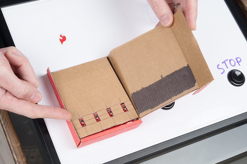
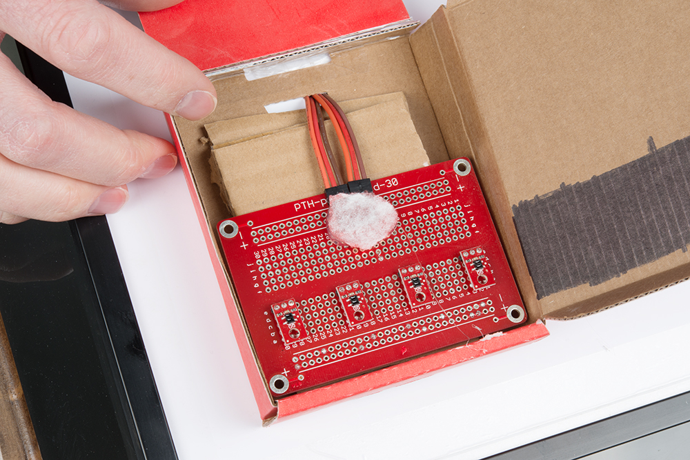
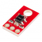
The crafty card reader uses four IR readers facing upwards to look at the cards pattern of black and white squares.
Exposed sensors. (Click to enlarge.)
Backside with exposed soldering. (Click to enlarge.)
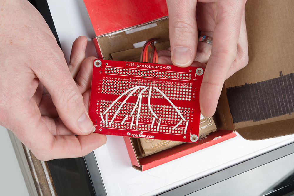
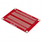
As shown above, it does require a fair amount of soldering. I opted to wire it up on one of our solderable bread board prototyping PCBs. These sensors do a good job at sensing black or white surfaces. They are often used in "line following" applications (like in some of our redbot tutorials).
Bottom side of crafty cards. (Click to enlarge.)

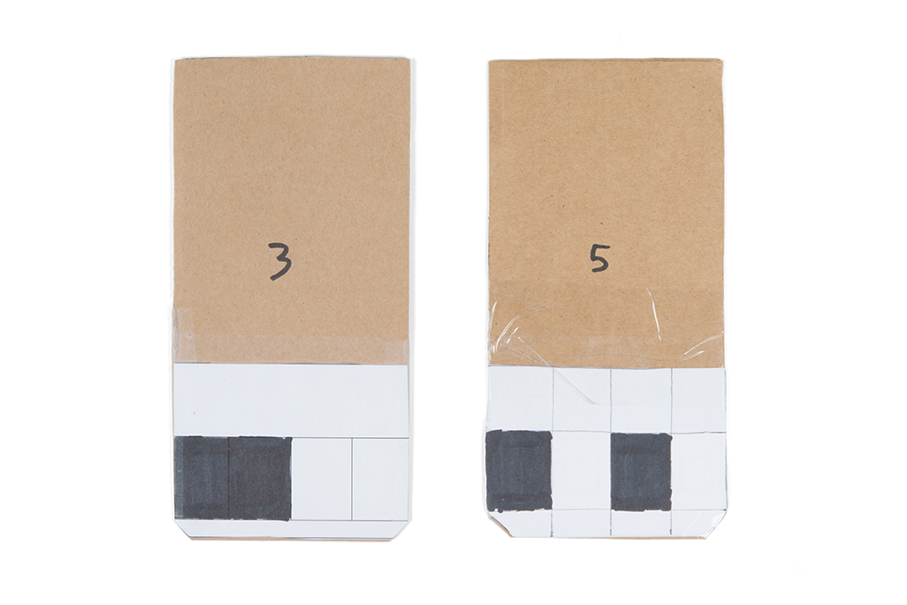
Six card "stickers". (Click to enlarge.)
On the left are a couple finished crafty cards. On the right are some more example "stickers" that could be used to make more cards. A black box will be read as a "cleared" or "zero" bit, and a white box will be read as a "set" or "one" bit.
Turns out these readers change dramatically with distance. They work great as line followers on a robot because they are usually at a very consistent distance from the floor surface. Well, with my card reader idea, my cards were not holding position so perfectly inside the reader box. Luckily, I was able to add a little more cardboard and make sort of a "wedge" inside the reader. This held the input cards at a more consistent distance from the IR readers. They were basically touching the readers, but that turned out okay!
Additional Tools and Materials:

SparkFun Beginner Tool Kit
TOL-14681Additional Reading:
You will also want to review the following tutorials as well.How to Solder: Through-Hole Soldering
Binary
Wiring
In order to wire up your crafty IR card reader, you will need to review the circuit for the IR sensor. The product page and bildr tutorial are both good resources.
The four IR sensors in this project are wired up so that each output is connected to Arduino pins: 4,5,6,7. You also need to power each IR sensor with 5V and GND. For my hookup, I chose to use Arduino pins D2 and D3 for power. Set D2 to an OUTPUT HIGH (5V power) and D3 to an OUTPUT LOW (GND). You could choose to use the 5V pin and GND pin on the Redboard Qwiic, but I chose to use D2/D3 for power so that I could plug all of my lines from the IR sensors into a single row of six pins.