SparkFun Inventor's Kit for RedBot
This Tutorial is Retired!
This tutorial covers concepts or technologies that are no longer current. It's still here for you to read and enjoy, but may not be as useful as our newest tutorials.
View the updated tutorial: Experiment Guide for RedBot with Shadow Chassis
 bri_huang
Experiment 6: Line Following with IR Sensors
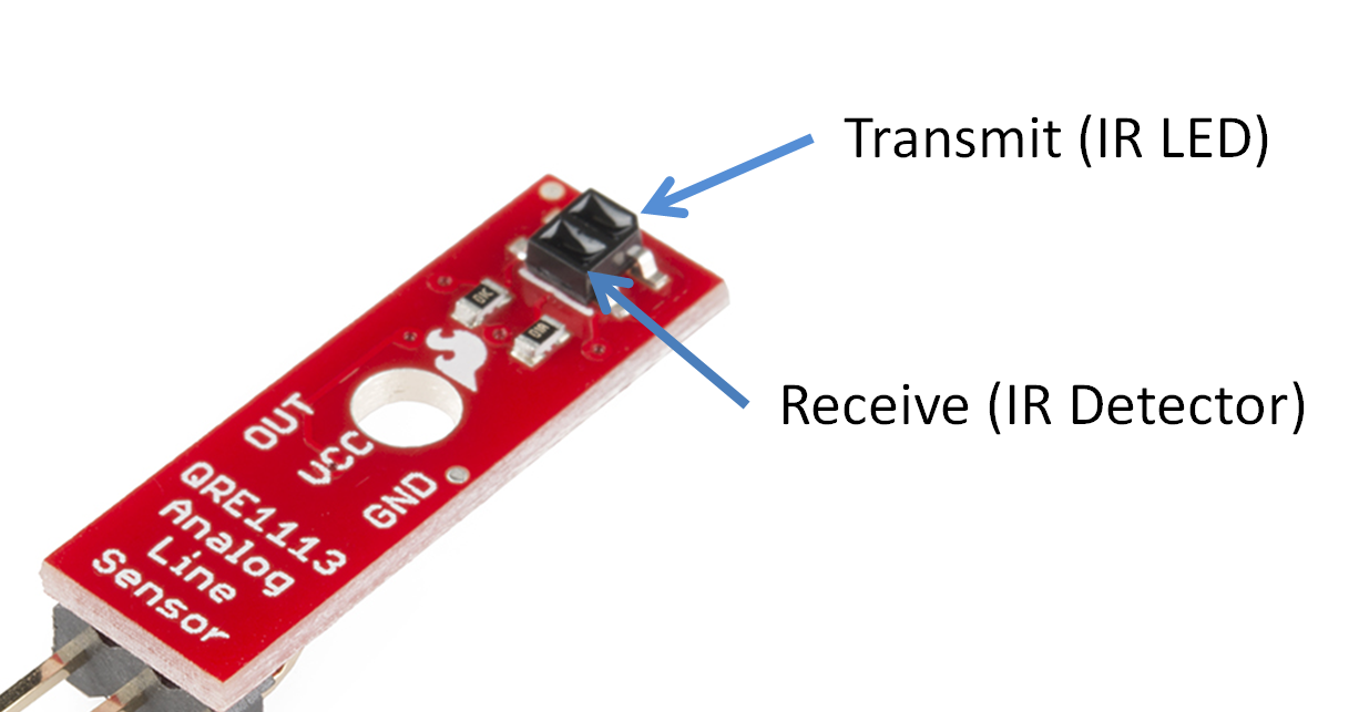
In this experiment, the RedBot will use IR Reflectance sensors to detect characteristics about the surface below the RedBot. The IR Reflectance sensor works by emitting a beam of infrared (IR) light down toward the surface below and measuring the reflected signal. On the IR Reflectance sensor, you will notice two small rectangular shapes. One is the IR transmitter and the other is the detector.
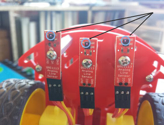
The IR Reflectance sensors work best when they are close to the surface below the RedBot. Using the 1-3/8" stand-offs, the sensor should be about 1/8" above the table. This is an optimal distance for the IR transmitter to illuminate the surface below and measure the reflected light. (Note: Human eyes are non sensitive to IR light, but if you use a CCD camera -- like the one in your phone -- you can see a small light shining out of the front element)
Experiment 6.1 -- Simple IRSensor Read
This example simply reads and prints the value of the three IR Sensors. Test out different scenarios to characterize the behavior of the IR sensor.
Upload this example code to the RedBot. **Go to File > Examples > RedBot_Experiments > Exp6_LineFollowing_IRSensors ** or copy and paste the example code below. After the code has successfully uploaded, open up the Serial Monitor to view the readings from the sensors.
language:c
/***********************************************************************
 * Exp6_1_LineFollowing_IRSensors -- RedBot Experiment 6.1
 *
 * This code reads the three line following sensors on A3, A6, and A7
 * and prints them out to the Serial Monitor. Upload this example to your
 * RedBot and open up the Serial Monitor by clicking the magnifying glass
 * in the upper-right hand corner.
 *
 * This sketch was written by SparkFun Electronics,with lots of help from
 * the Arduino community. This code is completely free for any use.
 *
 * 8 Oct 2013 M. Hord
 * Revised, 31 Oct 2014 B. Huang
 ***********************************************************************/

#include <RedBot.h>
RedBotSensor IRSensor1 = RedBotSensor(A3); // initialize a sensor object on A3
RedBotSensor IRSensor2 = RedBotSensor(A6); // initialize a sensor object on A6
RedBotSensor IRSensor3 = RedBotSensor(A7); // initialize a sensor object on A7

void setup()
{
  Serial.begin(9600);
  Serial.println("Welcome to experiment 6!");
  Serial.println("------------------------");
}

void loop()
{
  Serial.print("IR Sensor Readings: ");
  Serial.print(IRSensor1.read());
  Serial.print("\t");  // tab character
  Serial.print(IRSensor2.read());
  Serial.print("\t");  // tab character
  Serial.print(IRSensor3.read());
  Serial.println();
  delay(100);
}
After uploading this example, leaving the RedBot connected to your computer, set it down on a piece of paper with a dark line (at least 1/2" wide). You may use a Sharpie Marker, electrical tape, or dark paint. Open up the Serial Monitor to see the data and sensor readings by the RedBot.
Sensor Characterization Exercise
The IR Reflectance sensors operate in a pretty short range. They are optimal between 1/8" and 3/16" from the surface. Test this out with your own RedBot.
- Set the robot flat on your desk. What are the nominal values of the three sensors?
- Set the robot down on a piece of white paper. What are the values of the sensors now?
- Making some marks on your paper with different materials: electrical tape, paint, markers, pencils, etc.
- With the robot still sitting on your desk, turn out the lights or throw a blanket over it. What happens to the values of the sensor readings? What do you think is causing this?
- Slowly roll the robot towards the edge of a table. Watch the value as the sensor moves off the edge of the table. What is the sensor value when it rolls off the table?
We can now use these values to program our robot to do things like stay on a table or follow a dark line.
What You Should See
The RedBot won't do anything on its own with this example. It does, however, report back the sensor readings to the Serial Monitor in Arduino. Click on the Magnifying glass in the upper-right corner to open the Serial Monitor, and watch the values of the line followers change in different situations.
Learn More: Infrared
The IR Reflectance sensor is essentially an IR LED and an IR detector. It works by transmitting a beam of IR light downward toward the surface. If the detector is over a white surface, the reflected light is received by the detector and outputs a LOW signal. When the sensor is over a black surface where the light is absorbed or not reflected, the IR detector outputs a HIGH signal. The IR Sensor module provides an analog value from 0 - 1023 inversely dependent to the amount of reflected IR light.
The analog values read into the Arduino environment vary from 0 to 1023 because Arduino uses a 10-bit Analog-to-Digital Converter (ADC). A value of 0 corresponds to 0 Volts, and 1023 corresponds to 5V read in by the sensor.
Code to Note
To setup communication between the RedBot and your computer, we need to use the Serial object in Arduino. In the setup(), you will see a command: Serial.begin(9600); This initializes the Serial object and the determines the data rate (speed) that data will be transmitted & received betwen the RedBot and the computer. 9600 refers to a baud rate or the number of bis per second. 9600 is a good moderate data rate for most applications. However, other speeds including: 300, 1200, 2400, 4800, 9600, 14400, 19200, 28800, 38400, 57600, and 115200 are supported in Arduino.
language:c
Serial.begin(9600);
To send data from the RedBot to your computer, we have two commands: Serial.print(""); and Serial.println(""); The first command, Serial.print(""); simply prints the text in " " or data (in the form of a number or variable) to the Serial bus -- this shows up in the Serial monitor. The second command, Serial.println(""); does the same, but adds a carriage-return/line-feed (CRLF) character, moving the cursor to the next line.
language:c
Serial.print("IR Sensor Readings: ");

Serial.println(); // Sends a CRLF character -- moves cursor to next line.
Printing Special Characters
There are a few special characters that can be printed out. These follow all of the standard conventions used in C and C++. A few handy ones include:
| Code | Description |
| \t | TAB character |
| \" | Double quotation mark |
| \' | Single quotation mark |
| \n | CRLF - moves to next line |
RedBot Library
Library support for the line sensor is included in the main RedBot library. The line following sensors will be attached to pins A3, A6, and A7. We will create three objects for each of the three sensors with the following lines of code:
language:c
RedBotSensor IRSensor1 = RedBotSensor(A3);  // initialize a sensor object on A3
RedBotSensor IRSensor2 = RedBotSensor(A6);  // initialize a sensor object on A6
RedBotSensor IRSensor3 = RedBotSensor(A7);  // initialize a sensor object on A7
The RedBotSensor class has only one method of interest to us. It is xxxxxx.read(); This method returns a value from 0 to 1023 based on the input voltage of the sensor. Remember that the xxxxxx represents the name of the object -- In this case, IRSensor1, IRSensor2, or IRSensor3.
language:c
Serial.print(IRSensor1.read()); // prints out the sensor value of IRSensor1 to the Serial Monitor
Going Further
Modify the code to make the RedBot drive around and stop before it crosses a black line.
Use the xxxxxx.read() method to check the values and then write some code that will stop the
robot if the level of one of the sensors changes more than a certain amount.
You will need to use an if() statement. Go back to experiment 5 -- Bumpers to remind yourself how to make comparisons and conditional statements within an if() statement.
Let's take a look at a few basic scenarios.
The center moves off the line and the left sensor is now on the line. Adjust the power to turn / veer left until the center is back on the line.
The center moves off the line and the right sensor is now on the line. Adjust the power to turn / veer right until the center is back on the line.
The RedBot approaches a left turn, the center AND the left are BOTH on the line. Turn 90 degrees to the left.
The RedBot approaches a right turn, the center AND the right are BOTH on the line. Turn 90 degrees to the right.
Play around with these basic ideas to see if you can program your RedBot to:
A) Follow a straight line.
B) Follow a straight line and turn Left or Right.
C) Follow a maze traced out with electrical tape.
Troubleshooting
Nothing is printing in the serial monitor!
- Check to make sure the baud rate is set properly in the serial monitor. There's a drop-down menu in the lower right corner, and by default, this sketch wants the baud rate at 9600.
I don't see any change in my sensor values, no matter what I do!
- Double-check your connections.
- Try swapping out the sensor board with one of the others.
Experiment 6.2 -- Line Following Example

Here is a quick example of using the line following sensors to follow a dark line on a white background. The algorithm is fairly straight forward. If the center sensor is on the line, the RedBot drives straight (left & right motors are at the same speed). If the right sensor is on the line, we adjust by turning the RedBot to the right (driving the left a little faster and the right a little slower). Similarly, if the left sensor is on the line, the RedBot adjusts by turning to the left (driving the right a little faster and the left a little slower).
This example really only works when the RedBot is moving slowly, and it doesn't always handle sharp turns well. What can you do to make this example work better?
language:c
/***********************************************************************
 * Exp6_2_LineFollowing_IRSensors -- RedBot Experiment 6
 *
 * This code reads the three line following sensors on A3, A6, and A7
 * and prints them out to the Serial Monitor. Upload this example to your
 * RedBot and open up the Serial Monitor by clicking the magnifying glass
 * in the upper-right hand corner.
 *
 * This is a real simple example of a line following algorithm. It has
 * a lot of room for improvement, but works fairly well for a curved track.
 * It does not handle right angles reliably -- maybe you can come up with a
 * better solution?
 *
 * This sketch was written by SparkFun Electronics,with lots of help from
 * the Arduino community. This code is completely free for any use.
 *
 * 18 Reb 2015 B. Huang
 ***********************************************************************/

#include <RedBot.h>
RedBotSensor left = RedBotSensor(A3);   // initialize a left sensor object on A3
RedBotSensor center = RedBotSensor(A6); // initialize a center sensor object on A6
RedBotSensor right = RedBotSensor(A7);  // initialize a right sensor object on A7

// constants that are used in the code. LINETHRESHOLD is the level to detect
// if the sensor is on the line or not. If the sensor value is greater than this
// the sensor is above a DARK line.
//
// SPEED sets the nominal speed

#define LINETHRESHOLD 800
#define SPEED 60  // sets the nominal speed. Set to any number from 0 - 255.

RedBotMotors motors;
int leftSpeed;   // variable used to store the leftMotor speed
int rightSpeed;  // variable used to store the rightMotor speed

void setup()
{
    Serial.begin(9600);
    Serial.println("Welcome to experiment 6.2 - Line Following");
    Serial.println("------------------------------------------");
    delay(2000);
    Serial.println("IR Sensor Readings: ");
    delay(500);
}

void loop()
{
    Serial.print(left.read());
    Serial.print("\t");  // tab character
    Serial.print(center.read());
    Serial.print("\t");  // tab character
    Serial.print(right.read());
    Serial.println();

    // if on the line drive left and right at the same speed (left is CCW / right is CW)
    if(center.read() > LINETHRESHOLD)
    {
        leftSpeed = -SPEED;
        rightSpeed = SPEED;
    }

    // if the line is under the right sensor, adjust relative speeds to turn to the right
    else if(right.read() > LINETHRESHOLD)
    {
        leftSpeed = -(SPEED + 50);
        rightSpeed = SPEED - 50;
    }

    // if the line is under the left sensor, adjust relative speeds to turn to the left
    else if(left.read() > LINETHRESHOLD)
    {
        leftSpeed = -(SPEED - 50);
        rightSpeed = SPEED + 50;
    }

    // if all sensors are on black or up in the air, stop the motors.
    // otherwise, run motors given the control speeds above.
    if((left.read() > LINETHRESHOLD) && (center.read() > LINETHRESHOLD) && (right.read() > LINETHRESHOLD) )
    {
        motors.stop();
    }
    else
    {
        motors.leftMotor(leftSpeed);
        motors.rightMotor(rightSpeed);

    }
    delay(0);  // add a delay to decrease sensitivity.
}