SparkFun Inventor's Kit for RedBot
This Tutorial is Retired!
This tutorial covers concepts or technologies that are no longer current. It's still here for you to read and enjoy, but may not be as useful as our newest tutorials.
View the updated tutorial: Experiment Guide for RedBot with Shadow Chassis
 bri_huang
Experiment 7: Encoder
Knowing where your robot is can be very important. The RedBot supports the use of an encoder to track the number of revolutions each wheel has made, so you can tell not only how far each wheel has traveled but how fast the wheels are turning. Included in the Advanced RedBot kit is a magnetic hall effect sensor and an 8-pole magnetic disk (looks like a washer -- but, it's magnetic!).
This experiment is broken down into three parts: (1) Reading the encoders, (2) Driving a specific distance, and (3) Driving straight.
This first code example is pretty short, but with it we will introduce a how to interface and read the encoder inputs. Go to File > Examples > RedBot_Experiments > Exp7_1_RotaryEncoder or copy and paste the example code below and open up the Serial Monitor.
Experiment 7.1 - Exploring the Encoder
language:c
/***********************************************************************
 * Exp7_1_RotaryEncoder -- RedBot Experiment 7_1
 *
 * Knowing where your robot is can be very important. The RedBot supports
 * the use of an encoder to track the number of revolutions each wheels has
 * made, so you can tell not only how far each wheel has traveled but how
 * fast the wheels are turning.
 *
 * This sketch was written by SparkFun Electronics, with lots of help from
 * the Arduino community. This code is completely free for any use.
 *
 * 8 Oct 2013 M. Hord
 * Revised, 31 Oct 2014 B. Huang
 ***********************************************************************/

#include <RedBot.h>
RedBotMotors motors;

RedBotEncoder encoder = RedBotEncoder(A2, 10);  // initializes encoder on pins A2 and 10
int buttonPin = 12;
int countsPerRev = 192;   // 4 pairs of N-S x 48:1 gearbox = 192 ticks per wheel rev

// variables used to store the left and right encoder counts.
int lCount;
int rCount;

void setup()
{
  pinMode(buttonPin, INPUT_PULLUP);
  Serial.begin(9600);
  Serial.println("left    right");
  Serial.println("================");
}

void loop(void)
{
  // wait for a button press to start driving.
  if (digitalRead(buttonPin) == LOW)
  {
    encoder.clearEnc(BOTH);  // Reset the counters.
    motors.drive(150);        // Start driving forward.
  }

  // store the encoder counts to a variable.
  lCount = encoder.getTicks(LEFT);    // read the left motor encoder
  rCount = encoder.getTicks(RIGHT);   // read the right motor encoder

  // print out to Serial Monitor the left and right encoder counts.
  Serial.print(lCount);
  Serial.print("\t");
  Serial.println(rCount);

  // if either left or right motor are more than 5 revolutions, stop
  if ((lCount >= 5*countsPerRev) || (rCount >= 5*countsPerRev) )
  {
    motors.brake();
  }
}
What You Should See
If you open up the Serial Monitor you should see a window like this:
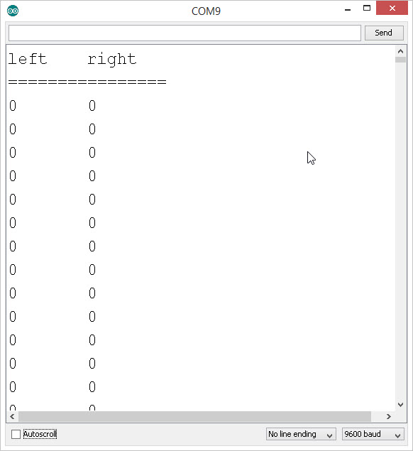
Turn each wheel one complete revolution, and watch what happens. What happens if you reverse directions?
You should see the numbers go up -- whether the wheel is turning clock-wise or counter clock-wise. The encoder simply counts the number of times the magnetic poles (N-S) change. The magnet has 8 poles (4 pairs of N-S), so you see 4 counts for every one turn of the magnet. So, why are we seeing more than just 4 counts? Because the motor is connected to a 48:1 gear box, one turn of the wheel is equal to 48 turns of the motor. 48 x (4 magnetic N-S pairs) = 192. Did you see about 192 counts?
Press the reset button to re-start the count at zero. Try it again.
Finally -- with the Serial Monitor window still open, push the D12 button on the RedBot. You should see the motors start spinning. You will also see the encoder counts track with the wheels. It should stop after 5 full rotations or at a count of about 960.
Code to Note
RedBotEncoder is another class in the RedBot library. This line initializes the encoder object with the left encoder connected to pin A2 and the right encoder connected to pin 10.
language:c
RedBotEncoder encoder = RedBotEncoder(A2, 10);  // initializes encoder on pins A2 and 10
One of the useful methods in the RedBotEncoder class is encoder.clearEnc([LEFT/RIGHT/BOTH]); This method clears the internal encoder counters for either the LEFT, RIGHT, or BOTH. This is useful for resetting the encoder count just before you start moving.
language:c
encoder.clearEnc(BOTH);  // Reset the counters.
To read the encoder count - also called "ticks" - we use the method encoder.getTicks[LEFT/RIGHT]); This returns a value representing the number of ticks or encoder counts. Because this number can be very large, we use a long variable type for it.
language:c
// store the encoder counts to a variable.
lCount = encoder.getTicks(LEFT);    // read the left motor encoder
rCount = encoder.getTicks(RIGHT);   // read the right motor encoder
Things to try
Looking at the code, we use the motors.brake(); method. Change this to motors.coast(). With motors.coast() the wheels coast and gradually come to a stop. How many more ticks or counts does a coast take compared to a brake()?
Experiment 7.2 - Driving a distance
In this example, we will use the encoder values and the circumference of the wheel to determine how far the RedBot moves.
The standard RedBot chassis has 65 mm (2.56 inch) diameter wheels. The circumference of a circle is equal to pi*D, or in this case, approximately 8.04 inches. And using the encoders, one circumference of the wheel (one full rotation) is also equal to 192 ticks of the encoder.
We will use all of this to write a function called driveDistance() that takes two parameters -- distance and motorPower to precisely move our robot. We can calculate the exact number of ticks (encoder counts) it will take to move a specific distance.
Go to File > Examples > RedBot_Experiments > Exp7_2_DriveDistance or copy and paste the example code below and open up the Serial Monitor.
language:c
/***********************************************************************
 * Exp7_2_DriveDistance -- RedBot Experiment 7.2
 *
 * In an earlier experiment, we used a combination of speed and time to
 * drive a certain distance. Using the encoders, we can me much more accurate.
 * In this example, we will show you how to setup your robot to drive a certain
 * distance regardless of the motorPower.
 *
 * This sketch was written by SparkFun Electronics, with lots of help from
 * the Arduino community. This code is completely free for any use.
 *
 * 8 Oct 2013 M. Hord
 * Revised, 31 Oct 2014 B. Huang
 ***********************************************************************/
#include <RedBot.h>

RedBotMotors motors;

RedBotEncoder encoder = RedBotEncoder(A2, 10);
int buttonPin = 12;
int countsPerRev = 192;   // 4 pairs of N-S x 48:1 gearbox = 192 ticks per wheel rev

float wheelDiam = 2.56;  // diam = 65mm / 25.4 mm/in
float wheelCirc = PI*wheelDiam;  // Redbot wheel circumference = pi*D

void setup()
{
  pinMode(buttonPin, INPUT_PULLUP);
  Serial.begin(9600);
}

void loop(void)
{
  // drive on button press.
  if (digitalRead(buttonPin) == LOW)
  {
    driveDistance(12, 150);  // drive 12 inches, at motorPower = 150.
  }
}

void driveDistance(float distance, int motorPower)
{
  long lCount = 0;
  long rCount = 0;
  float numRev;
  // debug
  Serial.print("driveDistance() ");
  Serial.print(distance);
  Serial.print(" inches at ");
  Serial.print(motorPower);
  Serial.println(" power.");

  numRev = (float) distance / wheelCirc;
  Serial.println(numRev, 3);
  encoder.clearEnc(BOTH);  // clear the encoder count
  motors.drive(motorPower);

  while (rCount < numRev*countsPerRev)
  {
    // while the left encoder is less than the target count -- debug print
    // the encoder values and wait -- this is a holding loop.
    lCount = encoder.getTicks(LEFT);
    rCount = encoder.getTicks(RIGHT);
    Serial.print(lCount);
    Serial.print("\t");
    Serial.print(rCount);
    Serial.print("\t");
    Serial.println(numRev*countsPerRev);
  }
  // now apply "brakes" to stop the motors.
  motors.brake();
}
What You Should See
In this example, when you push the D12 button, the RedBot should drive forward 12 inches and stop. If you have the Serial monitor open, you will see this debug information.
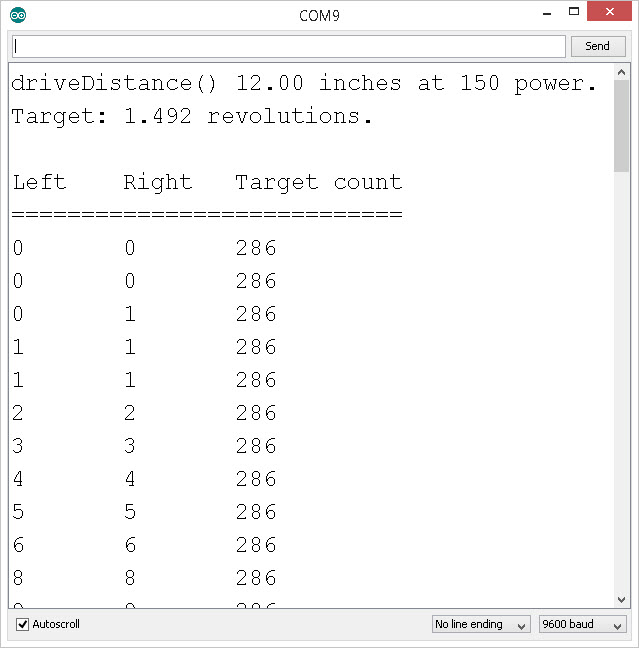
In the code, given a desired distance, it calculates the number of wheel rotations needed and the target number of encoder ticks (counts). As the wheels spin, it reports back the current count until it reaches its target.
Place the RedBot on a table or flat surface. Push the D12 button. How far did the RedBot move? Repeat this a few times. How far off is your RedBot? Try changing speeds. Is the RedBot more or less accurate when you change the motorPower?
Code to Note
In this example, we created a custom function called driveDistance(); It takes two input parameters -- distance and motorPower. If you look at the code, you will see where it calculates the number of revolutions (numRev = distance / wheelCirc;) and where it calculates the target encoder count (targetCount = numRev * countsPerRev;).
language:c
void driveDistance(float distance, int motorPower)
    {
        ...
    }
In this function, we use a while() loop. In this case, the while() loop will repeat over and over so long as rCount is less than targetCount. Inside the loop, we read both the left and the right encoder values, and print these out to the Serial Monitor.
language:c
while (rCount < targetCount)
    {
       ...
    }
Did you notice that the right motor doesn't spin the same speed as the left motor? Sometimes this happens with DC motors. In our next example, we will use the encoders to help us keep the RedBot driving straight.
Things to try
On the line of code that reads, driveDistance(12, 150); try changing the distance to something shorter or longer. Take a tape measure and see how accurate the RedBot is. Try changing the speed. How does the speed affect the accuracy of your driveDistance()?
Finally, you notice that in the while() loop we are only comparing the right encoder count, rCount. We assume that both the left and the right are pretty close -- but, try changing the rCount to lCount. How does this affect the behavior of your RedBot? Does it drive farther or shorter? Why?
Experiment 7.3 - Driving a "straight" distance
We have all of this information about how far each of the wheels are moving. We can now drive a precise distance at any speed, but our RedBot still curves a bit to one side or the other. Let's see if we can use the rCount and lCount information to steer our RedBot straight.
language:c
/***********************************************************************
 * Exp7_3_DriveStraight -- RedBot Experiment 7.3
 *
 * Knowing where your robot is can be very important. The RedBot supports
 * the use of an encoder to track the number of revolutions each wheels has
 * made, so you can tell not only how far each wheel has traveled but how
 * fast the wheels are turning.
 *
 * This sketch was written by SparkFun Electronics, with lots of help from
 * the Arduino community. This code is completely free for any use.
 *
 * 8 Oct 2013 M. Hord
 * Revised, 31 Oct 2014 B. Huang
 ***********************************************************************/
#include <RedBot.h>
RedBotMotors motors;

RedBotEncoder encoder = RedBotEncoder(A2, 10);
int buttonPin = 12;
int countsPerRev = 192;   // 4 pairs of N-S x 48:1 gearbox = 192 ticks per wheel rev

float wheelDiam = 2.56;  // diam = 65mm / 25.4 mm/in
float wheelCirc = PI*wheelDiam;  // Redbot wheel circumference = pi*D

void setup()
{
  pinMode(buttonPin, INPUT_PULLUP);
  Serial.begin(9600);
}

void loop(void)
{
  // set the power for left & right motors on button press
  if (digitalRead(buttonPin) == LOW)
  {
    driveStraight(12, 150);
  }
}

void driveStraight(float distance, int motorPower)
{
  long lCount = 0;
  long rCount = 0;
  long targetCount;
  float numRev;

  // variables for tracking the left and right encoder counts
  long prevlCount, prevrCount;

  long lDiff, rDiff;  // diff between current encoder count and previous count

  // variables for setting left and right motor power
  int leftPower = motorPower;
  int rightPower = motorPower;

  // variable used to offset motor power on right vs left to keep straight.
  int offset = 5;  // offset amount to compensate Right vs. Left drive

  numRev = distance / wheelCirc;  // calculate the target # of rotations
  targetCount = numRev * countsPerRev;    // calculate the target count

  // debug
  Serial.print("driveStraight() ");
  Serial.print(distance);
  Serial.print(" inches at ");
  Serial.print(motorPower);
  Serial.println(" power.");

  Serial.print("Target: ");
  Serial.print(numRev, 3);
  Serial.println(" revolutions.");
  Serial.println();

  // print out header
  Serial.print("Left\t");   // "Left" and tab
  Serial.print("Right\t");  // "Right" and tab
  Serial.println("Target count");
  Serial.println("============================");

  encoder.clearEnc(BOTH);    // clear the encoder count
  delay(100);  // short delay before starting the motors.

  motors.drive(motorPower);  // start motors

  while (rCount < targetCount)
  {
    // while the right encoder is less than the target count -- debug print
    // the encoder values and wait -- this is a holding loop.
    lCount = encoder.getTicks(LEFT);
    rCount = encoder.getTicks(RIGHT);
    Serial.print(lCount);
    Serial.print("\t");
    Serial.print(rCount);
    Serial.print("\t");
    Serial.println(targetCount);

    motors.leftDrive(leftPower);
    motors.rightDrive(rightPower);

    // calculate the rotation "speed" as a difference in the count from previous cycle.
    lDiff = (lCount - prevlCount);
    rDiff = (rCount - prevrCount);

    // store the current count as the "previous" count for the next cycle.
    prevlCount = lCount;
    prevrCount = rCount;

    // if left is faster than the right, slow down the left / speed up right
    if (lDiff > rDiff)
    {
      leftPower = leftPower - offset;
      rightPower = rightPower + offset;
    }
    // if right is faster than the left, speed up the left / slow down right
    else if (lDiff < rDiff)
    {
      leftPower = leftPower + offset;
      rightPower = rightPower - offset;
    }
    delay(50);  // short delay to give motors a chance to respond.
  }
  // now apply "brakes" to stop the motors.
  motors.brake();
}
Code to Note
In this code, we use the motors.leftDrive() and motors.rightDrive() to independently drive each side. In the while() loop, we calculate a "speed" based on the difference in the current encoder count compared to the last cycle.
If the left difference lDiff is greater than the right difference rDiff, we reduce the leftPower and increase the rightPower. And, if lDiff is less than rDiff, we increaes the leftPower and reduce the rightPower. This is a simple feedback loop that will help keep the RedBot driving straight.
Things to try
Take a look at the last experiment 7.3. There is a function called driveStraight that checks the difference in the lCount and the difference in the rCount from the previous encoder reading. It uses this to add or subtract a power offset to the right or left motors. On the line that reads: int offset = 5; Change the offset to a bigger number. How does this change the behavior of your RedBot.
Going Further
You have learned a lot so far! Encoders are great feedback sensors for robotics. In our earlier examples, when we used delay() and dead reckoning to drive a specific distance, we relied on the batteries maintaining a constant voltage and the motors to behave predictably each time. With encoders, we know exactly how far each wheel rotates.
For a challenge, write your own turn() function that uses the encoders to help the RedBot turn a 90 degree angle. With the encoders, your results should be pretty consistent each time.
Learn More: RedBot Sensor - Encoder
The wheel encoder on the RedBot is a Hall Effect Sensor that detects changes in magnetic field. As the the round magnetic disk mounted to the back of the drive motors rotates, it moves it's N/S poles past the sensor. Each transition from N/S is marked as a count. The disk is an 8-pole magnet (4 north-south pairs) and results in 4 ticks or counts for each revolution of the motor.
The motor is mounted inside a 48:1 gearbox. This means that the motor will spin 48 times for one full rotation of the wheel (48 x 4 = 192 counts).
Since the wheel is about 2.5 inches (65mm) in diameter, that corresponds to about eight inches or 200mm traveled per full revolution. So -- 192 counts of the encoder is equal to about 8 inches of linear travel.
Now, to forestall angry messages about conversions and precision of measurement (for instance, if you ask Google how many mm are in 2.5 inches, it’ll tell you 63.5, not 65, and the circumference of a 2.5 in diameter is certainly not exactly eight inches), I invite you to consider this your first lesson in precision and tolerance. Given all the tolerances involved in this system, eight inches/200mm per revolution is almost certainly a “good enough” answer, and if you need better than that, you’ll need a more expensive robotics platform.
Troubleshooting
The encoder counts aren't incrementing!
- Double check the wiring. Make sure that the encoders are plugged into ports A2 and 10 on the RedBot Mainboard.
- Make sure that the magnetic disk is still in place. If it falls off, a little super glue or epoxy will do the trick.
- Make sure that the encoder sensor is bent and next to the magnetic disk.