Basic Servo Control for Beginners
Introduction
From simply sweeping an object back and forth to adding steering to your robot or R/C car, hobby servos are a great way to add some motion to your next project. Servos allow you to easily control the speed, direction and position [1] of the output shaft with just three wires!
This tutorial covers a few different ways to control servos along with a project demonstrating how to control a servo from an external input. We will cover some basics of controlling servos with one example that requires no programming at all. Then we will control the servos with code using the Arduino IDE and Python. Feel free to jump to the example you would like to work with depending on the parts and code environment you prefer.
Recommended Reading
Before going through this tutorial, you may want to check out these related guides to get familiar with the concepts and parts used in the examples:
Pulse Width Modulation
Motors and Selecting the Right One
Hobby Servo Tutorial
Servo Motor Basics
Before we get to the examples in this tutorial, we'll want to review a few basics about servo motors. For a detailed rundown of servos, their background, and how they work, take a look at our Hobby Servo Tutorial.
Standard vs Continuous Servos
SparkFun carries two types of hobby servo motors: standard and continuous rotation. There are several differences between the two types but for the purpose of this tutorial we'll only review the primary distinctions between Standard and Continuous Rotation servos.
A standard servo moves on a rotation arc (usually 0-90° or 0-180°) and provides positional feedback to the controller. This lets you move it to a specific point on the rotation arc and the servo reports its position back to the controller. Standard servos work great for things like steering control in R/C applications, controlling a robotic gripper or controlling a pan/tilt bracket like we cover later in this tutorial.
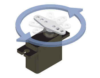
A continuous rotation servo (sometimes referred to as a full rotation or just 360° servo) behaves more like a standard DC motor. Instead of controlling the position of the servo, the controller sets the speed and direction of the motor. Continuous rotation servos work well as drive motors or other applications where you need to control the speed and direction of a motor with just a few wires.
Each type has their benefits and drawbacks so you will want to consider whichever type works best for your servo project.
Connector Pinout
One of the most important things to make note of with any servo is the pinout of the connector in order to prevent wiring things up incorrectly.
Most servos follow a specific color-code for Power (VCC), Ground (GND) and Control Signal. The table below lists the color-coding for three commonly used servo connector types. The pin numbering is almost universally the same but manufacturers may use different colors for the wires. If your servo does not match or you are not certain, it is always best to double-check the documentation for your servo.
| Pin Number & Name | Color Scheme - Hitec | Color Scheme - Futaba | Color Scheme - JR |
|---|---|---|---|
| 1. Ground (-) | Black | Black | Brown |
| 2. Power Supply (+) | Red | Red | Red |
| 3. Control Signal | Yellow or White | White | Orange |
Voltage Range and Power Supply
Next, you need to select a power supply for your servo project. Make sure the voltage provided by your power supply falls into the voltage range for your servo (commonly 4.8-6V but check the datasheet for your servo to be sure). Also, ensure your power supply can supply enough current to drive the servo. Again, the datasheet for your servo will have some helpful information to figure out the max current your servo may draw from your power supply. Usually, you can look at the stall current (if listed) in your servo's datasheet to determine the max current draw of your servo motor.
Control Signal Range
The last concept we want to revisit is a servo's control signal range. We're only going to cover the control signal range for this tutorial. For a more thorough explanation of a how a servo control signal works, check out this section of our Hobby Servo tutorial.
The primary thing to remember here is your servo's control signal pulse duration/width range. This is usually between 1 and 2 ms but can vary between manufacturers and servo types. Be sure to check your servo's specifications for the pulse range to avoid damaging the motor and gearbox. This is particularly important when you are sending PWM values from a microcontroller or single board computer like we demonstrate in the Arduino and Python sections.
Servo Control with the SparkFun Servo Trigger
Our first example demonstrates how to move a servo motor using the SparkFun Servo Trigger. This example requires no coding or computer connection but assembling it as recommended involves some through-hole soldering. If you are not familiar with soldering through-hole components, take a look at our How to Solder: Through-Hole Soldering tutorial to get started.
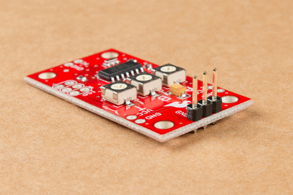
The Servo Trigger works by using pre-loaded firmware on the board to interpret the position of the three potentiometers on the board. The potentiometers determine the start and stop positions of the servo (labeled "A" and "B") as well as how long it takes for the servo to travel from the start and stop positions (labeled "T"). The movement sequence is initiated by connecting the IN and GND pins together. In this example, we are going to use this Concave Button to create that connection.
This is just a brief overview of how the SparkFun Servo Trigger works. For a full overview of the board and how to use it, take a look at our Hookup Guide for it.
Servo Trigger Hookup Guide
Required Materials
To follow along with this example, you will need the materials in the Wishlist below. Feel free to add or remove items to your cart depending on what parts you already have or which servo you would like to use.
Required Tools
Along with the parts listed above, we recommend the following tools and materials to assemble your circuit:
Hardware Hookup
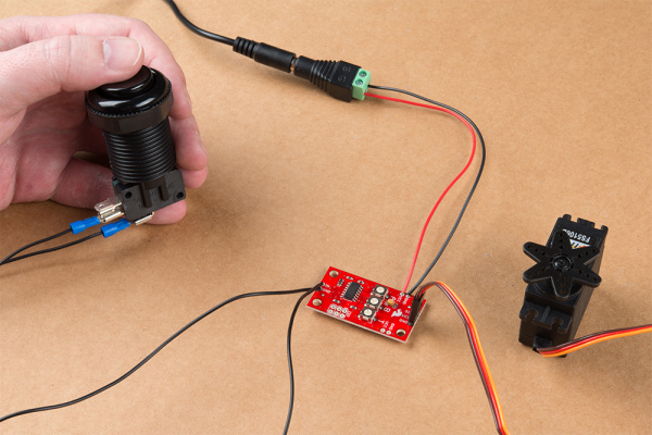
You will need to make the following connection. Below is a Fritzing diagram of the parts connected to the Servo Trigger. We'll go through step by step showing how to connect the components together.
Once you have all of your materials and tools together it's time to start assembling your circuit. We will start by soldering to the servo pins on the Servo Trigger. Clip off three pins from your chosen breakaway header and solder it to the row of 3 pins for the servo labeled SIG, VCC and GND. Using a male header lets us easily connect and disconnect our servo motor from the trigger board. If your wire harness for your servo is too short you can lengthen it with this servo extension cable.
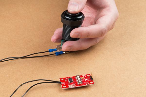
Next up is the connections to our button. Take your two spade connectors and solder the bare wire end to the IN and GND pins on the opposite side of the Servo Trigger from your servo connection. You can substitute other materials here to connect your control input (ie pushbutton) like hook-up wire if you want to use a different button that does not have a microswitch. Once that is soldered into place, connect the spade connector end of that wire soldered to IN to the connector labeled NO and the other spade connector soldered to GND to the COM connector on your button's microswitch.
The last part of assembling our circuit is making the connections for the power supply. You can solder headers into place and use jumper wires to make the connections to your power supply similar to the servo connection but since this is connected directly to our power supply, we're going to solder wire directly to the VCC and GND pins on the side of the Servo Trigger for a secure connection.
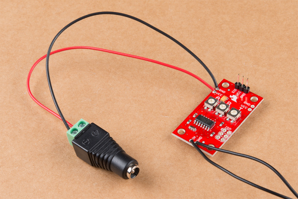
We want two lengths of wire for the Power and Ground inputs from our power supply. Strip one end of each wire and solder it to the VCC and GND pins on the side of the Servo Trigger as the photo below demonstrates.
Now, when using the DC Barrel Jack Adapter, strip away a some of the insulation on the other end of your wires now soldered to the Servo Trigger, insert them into the screw terminal on the end of the adapter and secure them into place using a screwdriver. Make sure to match the wire soldered to the VCC pin with the terminal labeled "+ and the other wire soldered to GND with the one labeled "-".
With everything soldered to your Servo Trigger and your button and servo connected (assuming you have not done so already), connect your power supply and press the button. You should see your servo sweep from one side to the other. Try adjusting the three potentiometers on your Servo Trigger to switch the direction, movement arc and movement time for your servo.
Troubleshooting Tips
Servo Not Moving or Powering On
The most common source of any problems with the servo not moving or not reacting to the button press will be a bad solder joint. If your servo is not powering up or is not moving when you press your button, check that your solder connections are completely connecting the pin or wire to the solder pad and the wires or solder joints are not touching each other. Also, make sure your power supply is plugged in fully to the DC Barrel Jack Adapter and your wall socket and is providing enough voltage to power the servo and the Servo Trigger. For tips on reworking bad solder joints, take a look at our Troubleshooting Tips Guide.
Erratic Movement
This may be caused by the potentiometers set beyond the servo's pulse range or possibly by having the button wired backward. Try adjusting the "A" and "B" potentiometers to fix erratic movement. If your servo is moving immediately when power is applied and then reacting unexpectedly to your button press, you may have one of your wires for the button connected incorrectly. Check to make sure you have the IN pin tied to the NO connector and the GND pin tied to the COM connector on your button.
Controlling a Servo with Arduino and Servo Library
Our second example circuit requires much less assembly and no soldering but it involves uploading and using code with the Arduino IDE. If you are not familiar with Arduino or do not have it installed on your computer, take a look through the guides below to install the IDE and get started with Arduino.
What is an Arduino?
Installing Arduino IDE
The SparkFun RedBoard Qwiic will act as our servo motor driver and controller using Pulse-Width Modulation (PWM).
Required Materials
To follow along with this example, you will need the materials listed below. Depending on what parts you already have or if you would like to use another development board or servo, you may want to adjust the items in your cart.
Hardware Assembly
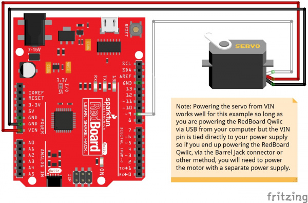
All we need to do for this circuit is connect our Servo Motor to our RedBoard like the diagram below demonstrates:
Though setting this circuit up is very simple since we are just using three pins on our RedBoard Qwiic, note that the Servo's power pin is connected to VIN and not 5V. The 5V pin can only source up to 250mA which is not enough to drive most servos so we use the VIN pin instead.
Arduino Code
Once you have your circuit wired up, it's time to upload some code! Connect your RedBoard (or other development board) to your computer with a USB cable and take note of the Port it shows up on. Now, open the Arduino IDE, copy the code below and paste it into a new sketch (making sure to delete the default code template).
Next, we need to select the board type (in this case Arduino/Genuino Uno) and COM port that the board enumerated to in the Tools menu. Then click the "Upload" button. If there were no errors during compilation and uploading, you should now see your servo moving back and forth.
language:c
/******************************************************************************
servo-sketch.ino
Example sketch for connecting a servo to a SparkFun RedBoard
  Servo Motor: (https://www.sparkfun.com/products/11965)
  SparkFun RedBoard: (https://www.sparkfun.com/products/13975)
Byron Jacquot@ SparkFun Electronics
May 17, 2016

**SparkFun code, firmware, and software is released under the MIT License(http://opensource.org/licenses/MIT).**

Development environment specifics:
Arduino 1.6.5
******************************************************************************/

#include <Servo.h>

Servo my_servo;

uint32_t next;

void setup()
{
  // the 1000 & 2000 set the pulse width
  // mix & max limits, in microseconds.
  // Be careful with shorter or longer pulses.
  my_servo.attach(9, 1000, 2000);

  next = millis() + 500;
}

void loop()
{
  static bool rising = true;

  if(millis() > next)
  {
    if(rising)
    {
      my_servo.write(180);
      rising = false;
    }
    else
    {
      my_servo.write(0);
      rising = true;
    }

    // repeat again in 3 seconds.
    next += 3000;
  }

}
Tips and Troubleshooting
Compilation/Upload Errors
If you run into any compilation or upload errors, the most common pitfall is the wrong Port was selected. Double check which port your RedBoard is on and retry. If you have multiple ports showing up in the "Port" menu, take note of which ports are available before plugging in your RedBoard and then select the new port that shows up in that menu after connecting it.
Another potential issue is if your code was not copied properly. The usual culprit for this is the code template was not entirely deleted/overwritten by the example. Take a quick look at your code and make sure you do not have any duplicated void loop();'s or void setup();'s or other rogue bits of code left over from the default template. The error printout at the bottom of the screen will give more thorough information on what the error is and can point you to any compiler errors in your code.
Servo Movement Problems
If your servo is not moving at all, you probably have a wire misplaced. Try rewiring the connections to ensure that your wiring has the servo connected to the correct pins on your RedBoard.
If your servo is jittery or seems like it is locking up, you may be driving it beyond the servo's pulse range. Check your servo's datasheet and adjust the second and third values in the servo.attach(9, 1000, 2000); function in the setup.
Controlling a Servo with Python and Pi Servo pHAT
Our third example demonstrates how to drive a servo using a Raspberry Pi and the SparkFun Servo pHAT for Raspberry Pi with the SparkFun PiServoHAT Python Module. The Servo pHAT can control up to 16 PWM devices so it is a great choice for projects using multiple servos along with other PWM devices like LEDs. The Raspberry Pi also has much more processing power than a development board like the RedBoard we used in the previous example so you can run all sorts of processes in the background for a complex project.
If you have never used a Raspberry Pi or the Servo pHAT before, we highly recommend reading through these tutorials before proceeding. The Getting Started with the Raspberry Pi tutorial is the most important in order to set up your Raspberry Pi as you cannot continue with this example without first configuring your Pi.
Python Programming Tutorial: Getting Started with the Raspberry Pi
Pi Servo pHAT (v2) Hookup Guide
Required Materials
To follow along with this example, you will need the following materials. Depending on what parts you already have, or if you would like to use a different Raspberry Pi or servo, you can adjust your cart accordingly.
Along with these parts, you will want a keyboard, mouse and monitor to connect to your Raspberry Pi to configure and interact with it. Alternatively, you can use another computer to do a headless setup for your Raspberry Pi. Also, if you already have a suitable SD card you would like to use, you can download and install the Raspbian OS for the Pi from the Raspberry Pi Foundation following the instructions from their Setting up your Raspberry Pi guide.
Hardware Hookup
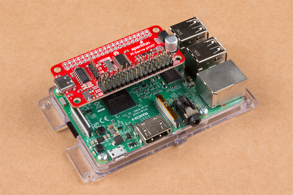
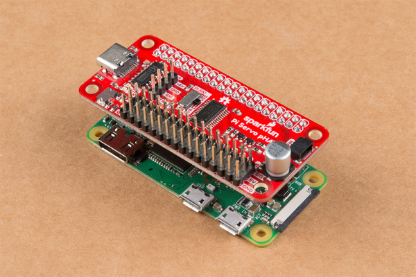
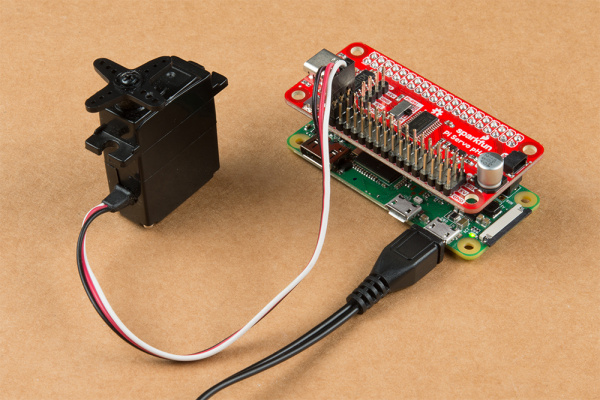
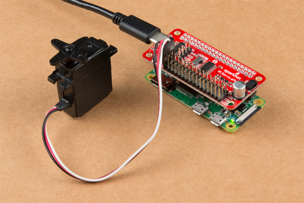
Hooking everything up with the Servo pHAT is pretty straightforward but there are a few things to note. With everything powered off, plug the pHAT on to the Pi's 2x20 GPIO Header, taking care to align it properly so it looks like the photos below.
Next, connect your servo to one of the 3-pin channel headers taking care to match the pins on the servo with the silkscreen labels on the Servo pHAT. The example we are using defaults to Channel 0 so, if you use a different channel, make sure to adjust the code accordingly. Do not connect servos to the Pi while it is powered on as the resulting current spike can cause the Raspberry Pi to reset.
Now, go ahead and plug in your Pi. Then turn it on and we're ready to move on to programming. The photos below show two options for powering the Raspberry Pi and Pi Servo pHAT.
Python Package
With all of the hardware assembled and your Pi configured and ready to go, it is time to install the Python module and run one of the examples. For this particular experiment, we'll use Example 2 - Full Sweep with 180 deg. Servo.
First, we need to install the package to our Pi. For the sake of keeping this tutorial short we'll only cover how to install the entire SparkFun Qwiic Python package. If you would like to install individual parts of the package or install them manually, please head on over to this section of our Hookup Guide for the Servo pHAT for detailed instructions.
The SparkFun Qwiic Python Package installs all the available Python packages for our Qwiic products and includes the required I2C driver package. On systems that support PyPi via pip3 (use pip for Python 2), installation is simple using the following commands:
For all users (note the user must have sudo privileges) enter the following command from your command prompt:
language:bash
sudo pip3 install sparkfun-qwiic
If you just want to install the package for the current user enter this command in your command prompt:
language:bash
pip install sparkfun-qwiic
With the SparkFun Qwiic package installed it is time to create and run our code. You can either download or copy the code below into a file. Then open/save the file and execute the code in your preferred Python IDE. For example, to run the example in the default development environment on Raspbian, IDLE, click Run>Run Module or use the F5 key. To stop the example, use the Ctrl + C key combination.
While the example is running, you should see your servo moving back and forth over a 180 degree arc.
language:python
#-----------------------------------------------------------------------
# Pi Servo Hat - Example 2
#-----------------------------------------------------------------------
#
# Written by  SparkFun Electronics, June 2019
# Author: Wes Furuya
#
# Compatibility:
#     * Original: https://www.sparkfun.com/products/14328
#     * v2: https://www.sparkfun.com/products/15316
#
# Do you like this library? Help support SparkFun. Buy a board!
# For more information on Pi Servo Hat, check out the product page
# linked above.
#
# This program is distributed in the hope that it will be useful, but
# WITHOUT ANY WARRANTY without even the implied warranty of
# MERCHANTABILITY or FITNESS FOR A PARTICULAR PURPOSE. See the GNU
# General Public License for more details.
#
# You should have received a copy of the GNU General Public License
# along with this program.  If not, see <http:www.gnu.org/licenses/>.
#
#=======================================================================
# Copyright (c) 2019 SparkFun Electronics
#
# Permission is hereby granted, free of charge, to any person obtaining
# a copy of this software and associated documentation files (the
# "Software"), to deal in the Software without restriction, including
# without limitation the rights to use, copy, modify, merge, publish,
# distribute, sublicense, and/or sell copies of the Software, and to
# permit persons to whom the Software is furnished to do so, subject to
# the following conditions:
#
# The above copyright notice and this permission notice shall be
# included in all copies or substantial portions of the Software.
#
# THE SOFTWARE IS PROVIDED "AS IS", WITHOUT WARRANTY OF ANY KIND,
# EXPRESS OR IMPLIED, INCLUDING BUT NOT LIMITED TO THE WARRANTIES OF
# MERCHANTABILITY, FITNESS FOR A PARTICULAR PURPOSE AND NONINFRINGEMENT.
# IN NO EVENT SHALL THE AUTHORS OR COPYRIGHT HOLDERS BE LIABLE FOR ANY
# CLAIM, DAMAGES OR OTHER LIABILITY, WHETHER IN AN ACTION OF CONTRACT,
# TORT OR OTHERWISE, ARISING FROM, OUT OF OR IN CONNECTION WITH THE
# SOFTWARE OR THE USE OR OTHER DEALINGS IN THE SOFTWARE.
#=======================================================================

"""
This example should be used with a 180 degree (range of rotation) servo
on channel 0 of the Pi Servo Hat.

The extended code (commented out), at the end of the example could be
used to test the full range of the servo motion. However, users should
be wary as they can damage their servo by giving it a position outside
the standard range of motion.
"""

import pi_servo_hat
import time

# Initialize Constructor
test = pi_servo_hat.PiServoHat()

# Restart Servo Hat (in case Hat is frozen/locked)
test.restart()

# Test Run
#########################################
# Moves servo position to 0 degrees (1ms), Channel 0
test.move_servo_position(0, 0, 180)

# Pause 1 sec
time.sleep(1)

# Moves servo position to 180 degrees (2ms), Channel 0
test.move_servo_position(0, 180, 180)

# Pause 1 sec
time.sleep(1)

# Sweep
#########################################
while True:
    for i in range(0, 180):
        print(i)
        test.move_servo_position(0, i, 180)
        time.sleep(.001)
    for i in range(180, 0, -1):
        print(i)
        test.move_servo_position(0, i, 180)
        time.sleep(.001)

#########################################
# Code below may damage servo, use with caution
# Test sweep for full range of servo (outside 0 to 180 degrees).
# while True:
#     for i in range(-45, 200):
#         print(i)
#         test.move_servo_position(0, i, 180)
#         time.sleep(.001)
#     for i in range(200, -45, -1):
#         print(i)
#         test.move_servo_position(0, i, 180)
#         time.sleep(.001)
Troubleshooting Tips
If you are having any difficulty getting your servo to move or recognize the Servo pHAT on your Pi, here are a few tips to help troubleshoot.
No Available Devices
If you see this error readout: OSError: [Errno 121] Remote I/O error, double check your connections to the GPIO header.
Also make sure that the I2C hardware is enabled on your Raspberry Pi. If it is not enabled, you will probably see this error readout: Failed to connect to I2C bus 1.. If you need help enabling I2C on your Pi, take a look at this section of our Raspberry Pi: SPI and I2C Tutorial.
Check your I2C Connection
A simple method to check if your Raspberry Pi can communicate with the Servo pHAT over I2C is to ping the I2C bus. On the latest releases of Raspbian Stretch, the i2ctools package should come pre-installed. If it isn't run the following command in the terminal:
language:bash
sudo apt-get install i2ctools
With the i2ctools package is installed, you can ping the I2C bus with the following command in the terminal:
language:bash
i2cdetect -y 1
You should see a table printed out in the terminal. If the Servo pHAT is connected and working properly you should see the address space for 0x40 marked with 40.
Current Draw Problems
If your servos are drawing more current that your power supply can handle, your Servo pHAT will not operate correctly and the Raspberry Pi may reboot or brown out intermittently.
If you have a particularly large servo, or many servos driving a heavy load, you might notice the Pi rebooting or browning out when using the USB port on the Pi to power both the Pi and the Servo pHAT. You can try switching to powering the Pi and Servo pHAT directly through the USB-C connector on the pHAT, but a better solution is to sever the Power Isolation jumper and power each device individually. We cover where to locate that jumper and how to modify it in the "Jumpers" subsection of the Hardware Overview section of the Servo pHAT Hookup Guide.
Direct Servo Control with the Qwiic Joystick
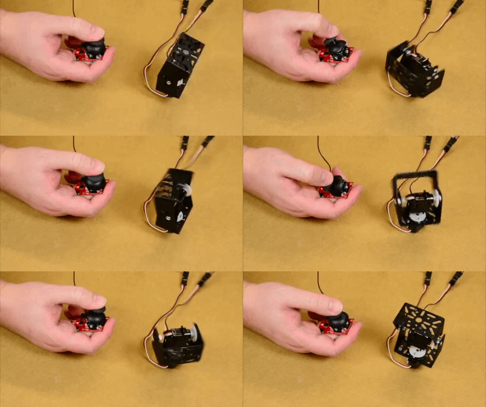
Controlling servos in loops can be good for projects where you just want something moving while powered but what if you want more of a direct ability to control your servo? This project looks to demonstrate how to do just that!
For this project, we'll use the Qwiic Joystick as our input to control two servos on a pan/tilt bracket attached to a RedBoard Qwiic. Make sure to check out the Qwiic Joystick Hookup Guide for more information about the Qwiic Joystick:
Qwiic Joystick Hookup Guide
Required Materials
To follow along with this example project you will need the following materials. Depending on what parts you already have, you may want to update your cart accordingly.
Hardware Hookup
The first thing we want to assemble for this project is our pan/tilt bracket with the two sub-micro servos. The assembly guide below gives some basic instructions on how to build the pan/tilt bracket with your servos.
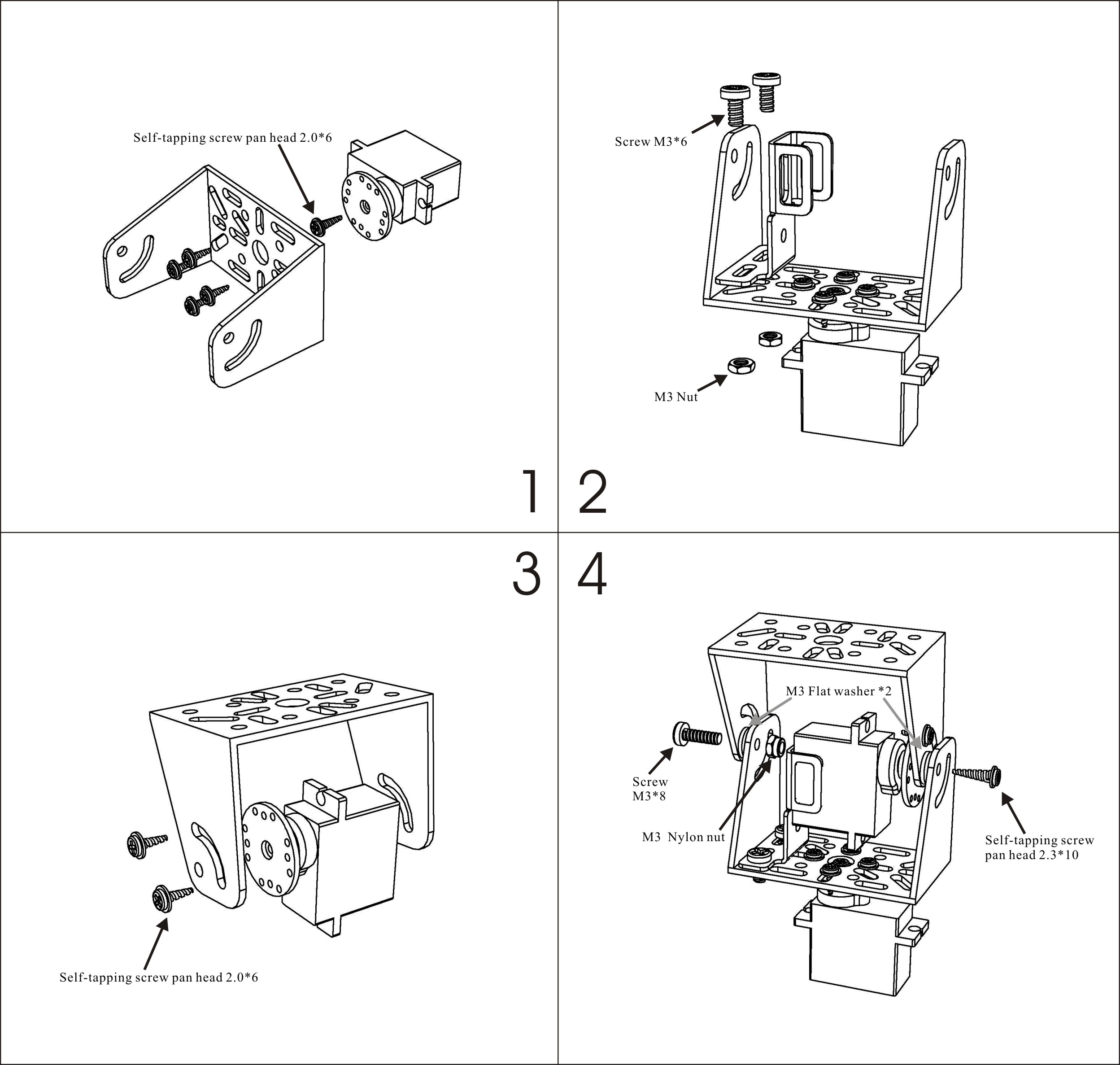
Take care to align the servos properly so you can take advantage of the full range of motion and avoid having to re-seat the servos once everything is wired up.
Depending on the fit, you may need to use three washers for spacing instead of 2 like the guide suggests.
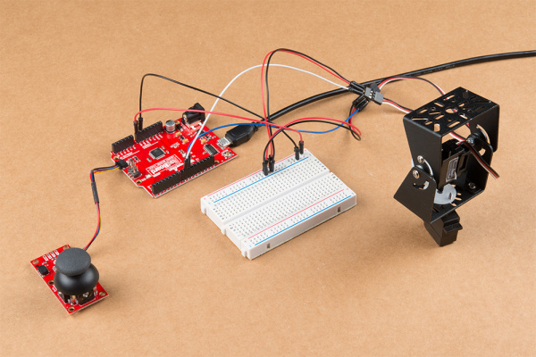
With the pan/tilt bracket assembled, connect the signal wires of the servos to the assigned I/O pins on your RedBoard and connect the Qwiic Joystick to the RedBoard with a Qwiic Cable. The example code uses D9 for the horizontal servo and D10 for the vertical servo by default but you can connect them to other pins if needed by modifying the servoH.attach(9); and servoV.attach(10); functions.
Finally, we need to connect the power supply pins for our servos. Just like with the Arduino Servo Library example from earlier, we are going to use the VIN pin on our RedBoard since the 5V pin can only source up to 250mA and our pan/tilt servos can pull in excess of 350mA with nothing attached to the bracket.
Since we have two servos for our pan/tilt bracket, we will use a breadboard to net the power pins for the servos together.
Connect the power and ground pins of each servo to the "+" and "-' rails of your breadboard and then, with the RedBoard unpowered, connect the VIN and GND pins on your RedBoard to the respective rails on the breadboard as well. Once you have all of the power and ground pins tied together properly, plug in your RedBoard via USB.
Arduino Code
With everything wired up, it is time to upload our code. First, we need to install the Qwiic Joystick Library if it is not installed already. You can manually install it by downloading it from the link above but we recommend installing the library through the Library Manager tool. Simply open that up and search for "SparkFun Qwiic Joystick" and click install. If you've never installed an Arduino library before, our Installing an Arduino Library Tutorial covers the entire process.
Now that the library is installed, go ahead and copy the code below and paste it into a new sketch. Select "Arduino/Genuino Uno" as your board (or if you are using another development board, select that) as well as the "Port" your board is on and upload the code.
language:c
/*
 Example code to control two servos using the SparkFun Qwiic Joystick.
 Code takes the readings of the Vertical (Y) and Horizontal (X) axes of the joystick
 and maps them to values between 0 and 180 degrees.

 Based off of the Arduino "Knob" example:

 Controlling a servo position using a potentiometer (variable resistor)
 by Michal Rinott <http://people.interaction-ivrea.it/m.rinott>

 modified on 8 Nov 2013
 by Scott Fitzgerald
 http://www.arduino.cc/en/Tutorial/Knob
*/

#include <Servo.h>
#include "SparkFun_Qwiic_Joystick_Arduino_Library.h"

JOYSTICK joystick; // create joystick object to send position values


Servo servoH;  // create servo object to control a servo
Servo servoV;

int h;    // variable to read the horizontal values from the Qwiic Joystick
int v;    // variable to read the vertical values from the Qwiic Joystick

void setup() {
  servoH.attach(9); // attaches servo1 on pin 9 to the servo object
  servoV.attach(10);  // attaches servo2 on pin 10 to the servo object
  Serial.begin(9600);
  Serial.println("Qwiic Joystick Servo Control");

  if(joystick.begin() == false)
  {
    Serial.println("Joystick not connected. Check wiring. Freezing...");
    while(1);
  }
}

void loop() {
  h = joystick.getHorizontal();   // reads the value of the Qwiic Joystick's horizontal axis (between 0 & 1023)
  h = map(h, 0, 1023, 0, 160);     // scale it to use it with the servo (value between 0 and 180)
  servoH.write(h);                  // sets the horizontal servo position according to the scaled value
  v = joystick.getVertical(); // reads the value of the Qwiic Joystick's vertical axis (between 0 & 1023)
  v = map(v, 0, 1023, 0, 165);
  servoV.write(v);
  delay(15);    // waits for the servo to get there
  /*Serial.print("X: ");  //uncomment these lines to view the serial print of the x and y axes of the Qwiic Joystick
  Serial.print(joystick.getHorizontal());   //these can be helpful for debugging or identifying any drift on your joystick
  Serial.print("Y: ");
  Serial.print(joystick.getVertical());
  Serial.println();*/
}
Once the code finishes uploading try moving the joystick around. You should see the servo connected to pin 9 react to movements on the horizontal axis and the servo on pin 10 will react to movements on the vertical axis just like the GIF below.
Troubleshooting Tips
Here are some tips if you run into some common pitfalls with this example.
Compilation and Upload Errors
If you end up getting any compilation errors such as avrdude stk500_recv() programmer is not responding or something similar regarding the target device (aka our RedBoard), make sure you have selected the correct Port for your RedBoard as well as the correct board type.
If you see errors similar to SparkFun_Qwiic_Joystick_Arduino_Library.h: No such file or directory, the Qwiic Joystick library was not installed properly. Check to make sure the library is installed and is the latest version using the Arduino Library Manager tool.
Power Issues
Since we are using a breadboard for this example, a common cause of any power issues (e.g. the entire circuit is not turning on when plugged into USB) is a misplaced wire. Check that you have all of your power and ground wires properly connected on your breadboard. A common error is one or more of the wires is backward (i.e. power to ground or vice versa). Verify those are plugged into the right rail on your breadboard and are making a good connection to both the servo and your RedBoard.
Resources and Going Further
Now that you have a solid base understanding of how to control servos in a variety of ways, it's time to think about how you can integrate them into some projects! You can add all sorts of different things to the pan/tilt bracket like a camera or LED array. You can swap the Qwiic Joystick from the last project for another sensor like an IMU or you could even send the joystick data over a wireless connection and be on your way to creating your own R/C car or robot!
For some inspiration on ways to integrate servos into projects, take a look at the tutorials below using servos.
Building a Safe Cracking Robot
Setting Up the Pi Zero Wireless Pan-Tilt Camera
SparkFun ESP32 DMX to LED Shield
LED Gumball Machine
Or check out these blog posts for inspiration for your own servo project:
