Basic Character LCD Hookup Guide
Contributors:
followr,  MikeGrusin,
  bboyho
Hardware Overview
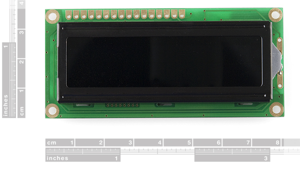
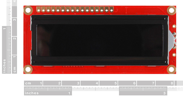
Note: Depending on how the LCD was manufactured, you may have a green or red PCB. Throughout this tutorial, you will see both colors but the overall functionality will be the same for a basic character LCD!
 |
 |
| LCD w/ Green PCB | LCD w/ Red PCB |
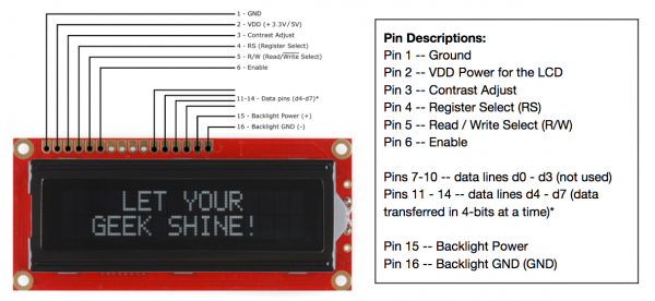
A basic character LCD has 16 pins (with the exception of an RGB LCD which has 18 pins), and it is polarized. The pins are numbered from left to right, 1 through 16. The LCD utilizes an extremely common parallel interface LCD driver chip from Hitachi called the HD44780. Thankfully, the Arduino community has developed a library to handle a great deal of the software-to-hardware interface. Below is a list of each of the pins on the LCD.
Click on image for a closer view.
Input Voltage and Logic Levels
For the scope of this tutorial, we are going to be connecting a 5V Arduino to the 5V basic character LCD. Depending on your LCD's specifications, the input voltage may be 3.3V or 5V. The logic levels will be the same as the input voltage. Just make sure to match the voltages for the microcontroller and LCD.
