Basic Character LCD Hookup Guide
 MikeGrusin,
  bboyho
RGB LED Backlight Control
Previous examples connect the white LED backlight to power. The following example is specifically for those using an LCD with a RGB LED backlight. The only difference between the connection is the LED's backlight on pins 15-18.
Copy and paste the code below. Just make sure to select the correct board (in this case the Arduino/ Genuino Uno) and the COM port that the Arduino enumerated on. Then upload the code to your Arduino.
language:c
/* LCD-RGB_Hello World.ino

  By: Ho Yun "Bobby" Chan
  SparkFun Electronics
  Date: 5/22/2019
  License: This code is public domain.

  Modified example code of Arduino.cc's Hello World.
  https://www.arduino.cc/en/Tutorial/HelloWorld

  Demonstrates the use a 16x2 LCD display with a common cathode
  RGB LED backlight. The LiquidCrystal library works with all
  LCD displays that are compatible with the Hitachi HD44780 driver.
  There are many of them out there, and you can usually tell them
  by the 16-pin/18-pin interface.

  This sketch prints "Hello world!" to the LCD,
  shows the time since the Arduino was last reset, and
  controls the RGB backlight. The backlight displays
  the primary, secondary, and tertiary colors.

  Hardware Hookup:
    LCD VSS pin to GND
    LCD VCC pin to 5V
    10kΩ Potentiometer to LCD VO pin (pin 3)
    LCD RS pin to digital pin 13
    LCD R/W pin to GND
    LCD Enable pin to digital pin 12
    .
    .
    .
    .
    LCD D4 pin to digital pin 11
    LCD D5 pin to digital pin 10
    LCD D6 pin to digital pin 9
    LCD D7 pin to digital pin 8
    LCD Backlight - K (Common Cathode) to GND
    LCD Backlight - Anode-RED to 330Ω to PWM pin 6
    LCD Backlight - Anode-GREEN to 330Ω to PWM pin 5
    LCD Backlight - Anode-BLUE to 330Ω to PWM pin 3

  Note: You may need to adjust the current limiting resistor
  and PWM value for the LED depending on the voltage used.
  Depending on the mixed color, this may result in a lower
  brightness.

  https://learn.sparkfun.com/tutorials/basic-character-lcd-hookup-guide

*/

//Include the library code:
#include <LiquidCrystal.h>

//LED Backlight
int ledR = 6;//hardware PWM
int ledG = 5;//hardware PWM
int ledB = 3; //hardware PWM
int redIntensity = 255; //value to adjust since red can be brighter than the other colors depending on the resistor value used

//Initialize the library by associating any
//needed LCD interface pin with the Arduino pin
//number it is connected to
const int rs = 13, en = 12, d4 = 11, d5 = 10, d6 = 9, d7 = 8;
LiquidCrystal lcd(rs, en, d4, d5, d6, d7);

void setup() {
  //Set up the LCD's number of columns and rows:
  lcd.begin(16, 2);

  //Clear the display
  lcd.clear();

  //Test Colors
  sequenceTest();

  lcd.setCursor(0, 0);
  //Print a message to the LCD.
  lcd.print("Hello, world!");
  //Turn on backlight for red
  redON();
  lcd.setCursor(0, 1);
  lcd.print("Red");
  delay(1500);
  lcd.setCursor(0, 1);
  lcd.print("                ");

}

void loop() {
  // set the cursor to column 0, line 1
  // (note: line 1 is the second row, since counting begins with 0):
  lcd.setCursor(0, 1);
  // print the number of seconds since reset:
  lcd.print(millis() / 1000);
}

void allOFF() {
  analogWrite(ledR, 0);
  analogWrite(ledG, 0);
  analogWrite(ledB, 0);
}

void allON() {
  analogWrite(ledR, redIntensity);
  analogWrite(ledG, 255);
  analogWrite(ledB, 255);
}

void redON() {
  analogWrite(ledR, redIntensity);
  analogWrite(ledG, 0);
  analogWrite(ledB, 0);
}

void roseON() {
  analogWrite(ledR, redIntensity);
  analogWrite(ledG, 0);
  analogWrite(ledB, 128);
}

void magentaON() {
  analogWrite(ledR, redIntensity);
  analogWrite(ledG, 0);
  analogWrite(ledB, 255);
}

void violetON() {
  analogWrite(ledR, 128);
  analogWrite(ledG, 0);
  analogWrite(ledB, 255);
}

void blueON() {
  analogWrite(ledR, 0);
  analogWrite(ledG, 0);
  analogWrite(ledB, 255);
}

void azureON() {
  analogWrite(ledR, 0);
  analogWrite(ledG, 128);
  analogWrite(ledB, 255);
}

void cyanON() {
  analogWrite(ledR, 0);
  analogWrite(ledG, 255);
  analogWrite(ledB, 255);
}

void springgreenON() {
  analogWrite(ledR, 0);
  analogWrite(ledG, 255);
  analogWrite(ledB, 128);
}

void greenON() {
  analogWrite(ledR, 0);
  analogWrite(ledG, 255);
  analogWrite(ledB, 0);
}

void chartreuseON() {
  analogWrite(ledR, 128);
  analogWrite(ledG, 255);
  analogWrite(ledB, 0);
}

void yellowON() {
  analogWrite(ledR, redIntensity);
  analogWrite(ledG, 255);
  analogWrite(ledB, 0);
}

void orangeON() {
  analogWrite(ledR, redIntensity);
  analogWrite(ledG, 51);
  analogWrite(ledB, 0);
}

void sequenceTest() {

  lcd.setCursor(0, 0);
  lcd.print("Backlight Color");

  lcd.setCursor(0, 1);          //set the cursor to the second row, 1st position
  lcd.print("                 ");//clear 2nd row
  lcd.setCursor(0, 1);          //set the cursor to the second row, 1st position
  lcd.print("Red");
  redON();//good
  delay(1500);

  lcd.setCursor(0, 1);           //set the cursor to the second row, 1st position
  lcd.print("                 ");//clear 2nd row
  lcd.setCursor(0, 1);           //set the cursor to the second row, 1st position
  lcd.print("Rose");
  roseON();
  delay(1500);

  lcd.setCursor(0, 1);           //set the cursor to the second row, 1st position
  lcd.print("                 ");//clear 2nd row
  lcd.setCursor(0, 1);           //set the cursor to the second row, 1st position
  lcd.print("Magenta");
  magentaON();//good
  delay(1500);

  lcd.setCursor(0, 1);           //set the cursor to the second row, 1st position
  lcd.print("                 ");//clear 2nd row
  lcd.setCursor(0, 1);           //set the cursor to the second row, 1st position
  lcd.print("Violet");
  violetON();
  delay(1500);

  lcd.setCursor(0, 1);           //set the cursor to the second row, 1st position
  lcd.print("                 ");//clear 2nd row
  lcd.setCursor(0, 1);           //set the cursor to the second row, 1st position
  lcd.print("Blue");
  blueON();//good
  delay(1500);

  lcd.setCursor(0, 1);           //set the cursor to the second row, 1st position
  lcd.print("                 ");//clear 2nd row
  lcd.setCursor(0, 1);           //set the cursor to the second row, 1st position
  lcd.print("Azure");
  azureON();//good
  delay(1500);

  lcd.setCursor(0, 1);           //set the cursor to the second row, 1st position
  lcd.print("                 ");//clear 2nd row
  lcd.setCursor(0, 1);           //set the cursor to the second row, 1st position
  lcd.print("Cyan");
  cyanON();//good
  delay(1500);

  lcd.setCursor(0, 1);           //set the cursor to the second row, 1st position
  lcd.print("                 ");//clear 2nd row
  lcd.setCursor(0, 1);           //set the cursor to the second row, 1st position
  lcd.print("Spring Green");
  springgreenON();//good
  delay(1500);

  lcd.setCursor(0, 1);           //set the cursor to the second row, 1st position
  lcd.print("                 ");//clear 2nd row
  lcd.setCursor(0, 1);           //set the cursor to the second row, 1st position
  lcd.print("Green");
  greenON();//good
  delay(1500);

  lcd.setCursor(0, 1);           //set the cursor to the second row, 1st position
  lcd.print("                 ");//clear 2nd row
  lcd.setCursor(0, 1);           //set the cursor to the second row, 1st position
  lcd.print("Chartreuse");
  chartreuseON();
  delay(1500);

  lcd.setCursor(0, 1);           //set the cursor to the second row, 1st position
  lcd.print("                 ");//clear 2nd row
  lcd.setCursor(0, 1);           //set the cursor to the second row, 1st position
  lcd.print("Yellow");
  yellowON();//good
  delay(1500);

  lcd.setCursor(0, 1);           //set the cursor to the second row, 1st position
  lcd.print("                 ");//clear 2nd row
  lcd.setCursor(0, 1);           //set the cursor to the second row, 1st position
  lcd.print("Orange");
  orangeON();//good
  delay(1500);

  lcd.setCursor(0, 1);           //set the cursor to the second row, 1st position
  lcd.print("                 ");//clear 2nd row
  lcd.setCursor(0, 1);           //set the cursor to the second row, 1st position
  lcd.print("White");
  allON();
  delay(1500);

  lcd.setCursor(0, 1);           //set the cursor to the second row, 1st position
  lcd.print("                 ");//clear 2nd row
  lcd.setCursor(0, 1);           //set the cursor to the second row, 1st position
  lcd.print("LEDs Off");
  allOFF();
  delay(1500);

  lcd.setCursor(0, 0);           //set the cursor to the second row, 1st position
  lcd.clear();                   //Clear the display
}
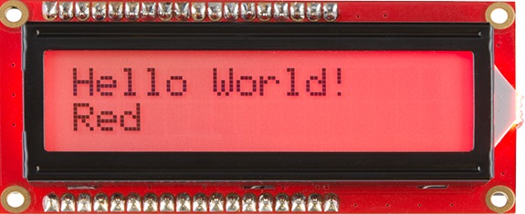
After uploading, you will notice the same "Hello, world!" and time since the Arduino was last reset in the first example. The only difference is that the current color of the backlight will be printed as it cycles through each of the primary, secondary, and tertiary colors. You should see something similar to the image below.