Basic Character LCD Hookup Guide
 MikeGrusin,
  bboyho
Hardware Assembly
LCDs usually come without a microcontroller to control the display. To connect, you will need a strip of header pins, a potentiometer to adjust the contrast of the display, breadboard, and wires. Depending on the LCD, you may need a current limiting resistor to to limit the current to the LED backlight. You will need to solder the header pins of your choice to the display in order to plug it into your breadboard. If you have not soldered before, we recommend looking at our soldering tutorial.
How to Solder: Through-Hole Soldering
While you can use any standard 16x2 alphanumeric LCD, the white on black display supplied with the kit looks übercool. The photographs in this guide are of a standard black on green display so yours may look different. The "16x2" refers to the display having two rows of sixteen characters each — other displays are available which are 8x1 or 20x4.
Soldering Tips
It is pretty straightforward to solder the header pins to the LCD module. Make sure to keep the soldering iron in contact with the joints for no more than about three seconds. There small risk of the damaging the existing components on the board with excess heat. You also need to be careful to keep the soldering iron away from the already soldered components on the board — you're probably not yet ready to do surface mount soldering repair.
Insert Headers to the LCD
Before soldering, perform a "test fit" of parts. A test fit gives you a chance to double check if you've got the parts you need and ensures that they fit together. For this connection, break a row of 16x1 male headers and insert the header pins into the holes on the LCD module as shown in the image below. If you are using an RGB LED, you will need a row of 18x1 male headers.
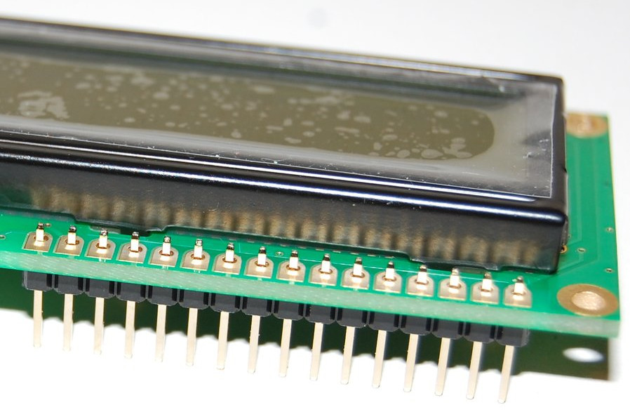
Ensure that you don't have one pin too many or too few in your header strip. Also make sure the black plastic strip of the header is positioned on the underside of the printed circuit board (PCB) so that you have plenty of pin length below the PCB to plug into your breadboard or a socket. The longest part of the pins should be below the PCB. The pin header provides connections that carry the data signals for controlling what the display... displays. They also carry power to the small microcontroller behind the black blob on the module and to the LED backlight if your display has one.
Soldering Male Headers
If you've done a test fit then your header should be in place. Ensure the header is aligned as parallel as possible to the edge of the board. Then solder the far left or right pin into place as shown in the image below.
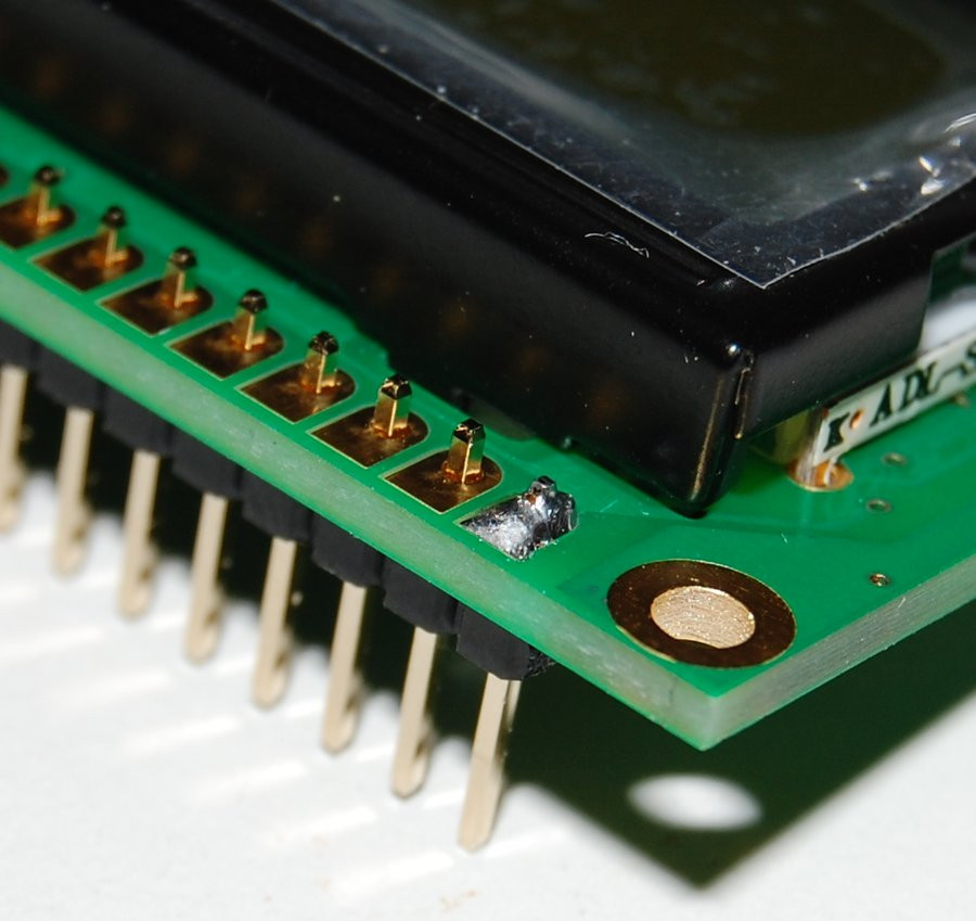
Because there's not a lot of room it is easiest to feed the solder from behind pin while the soldering iron tip is between the pins, resting on the PCB pad with the side of iron against the side of pin you're soldering. The reason we start with just one pin is because it makes it easier to obtain the correct alignment and fix any mistakes.
If the alignment of the header isn't quite right, carefully reheat the solder joint and move the header slightly. Don't move the header when the solder joint is still in it's liquid state however, or you'll end up with a poor joint.
Once you're happy with the alignment of the header you can solder another pin into place — we recommend soldering the pin at the opposite end of the header to the first pin you soldered. The reason for this is that once the two end pins are in place, the alignment won't change.
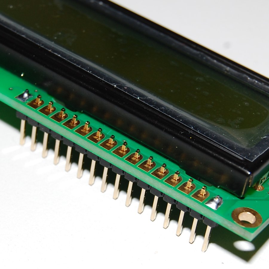
Double check the alignment is still okay and if it's not quite right you can reheat the joint and carefully move the pin. After you've confirmed the alignment, you can solder the remaining pins into place.
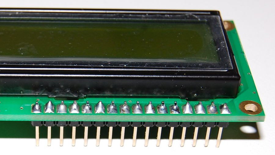
Ensure that the solder covers the plated through hole's pad and pins as shown in the image below for the best connection.
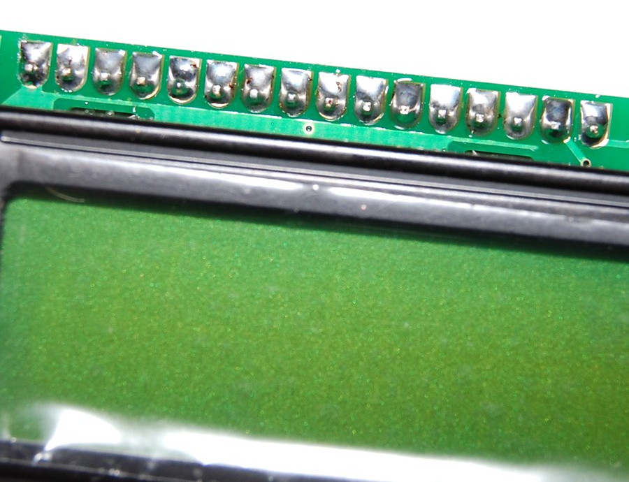
And now the soldering is complete!
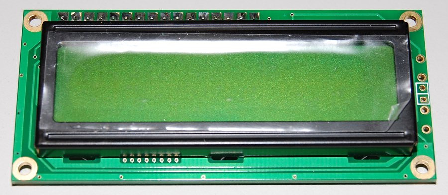
Completed LCD
Your display module should now look like the image below. One additional detail to note is that the pin header is usually at the "top" of the display — so keep that in mind if you plan to mount it anywhere. Remember to always test the display out before mounting to a project.
Now it is time to connect your LCD to a microcontroller! For the scope of this tutorial, we'll use an Arduino.