|
 |
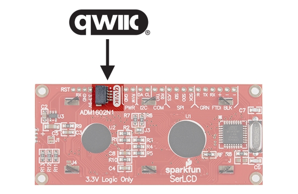
| Newer versions have qwiic connector! Silk will look like "ADM1602N1". | Older versions do not have a qwiic connector. Silk will look like "ADM1602N_v2.6" |
|
|
| Newer versions have qwiic connector! Silk will look like "ADM1602N1". | Older versions do not have a qwiic connector. Silk will look like "ADM1602N_v2.6" |
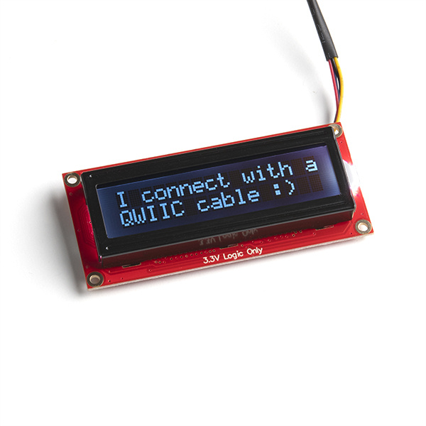
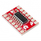
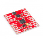
The AVR-based serial enabled LCD (a.k.a. SerLCD) is a simple and cost effective solution for adding Liquid Crystal Displays (LCDs) into your project. The PCB design on the back of the screen includes an ATmega328P that handles all of the screen control. It can accept commands via serial, I2C and SPI. The latest versions also include a Qwiic connector for solder-less single-cable connection setup. This simplifies the number of wires needed and allows your project to display all kinds of text and numbers. We offer three varieties of the AVR-based Serial Enabled LCDs:
The firmware is fully opensource and available for download at the GitHub repo here:
This allows for any customizations you may need. Uploading firmware (custom or updates), is easily done from the Arduino IDE using a Serial Basic. See firmware update instructions in the troubleshooting section of this tutorial for more info.
Also note, the example code used below is all available in the repo (along with many more examples). Before beginning this tutorial, it's a good idea to clone the repository (or download the entire repo as a zip), to grab all of the examples. But if you prefer, you can always use the "COPY CODE" button on each of the examples below.
Note that these all have identical firmware and can accept the same commands. However, you must adjust your display characters and cursor position as necessary for each model. Also note, there is a jumper on the back of each screen, and this "tells" the firmware how to correctly set the lines and columns for each screen.
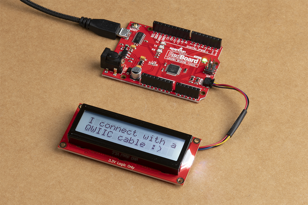
If you are using Qwiic, then you will only need a Redboard Qwiic, a Qwiic cable, and a Micro-B USB cable for programming.
For non-qwiic setups, you may need the following materials in this wishlist. Depending on what you have, you may not need everything on this list. Add it to your cart, read through the guide, and adjust the cart as necessary.
You may need a soldering iron, solder, and general soldering accessories, and screw driver depending on your setup.

If you aren’t familiar with the following concepts, we recommend checking out these tutorials before continuing.
The AVR-based SerLCD has many features that make it powerful and economical:
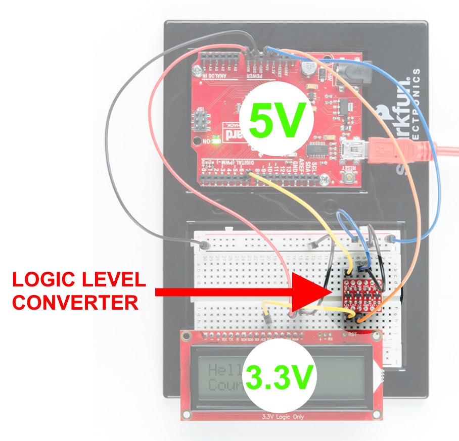
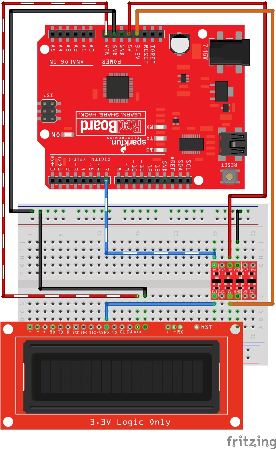
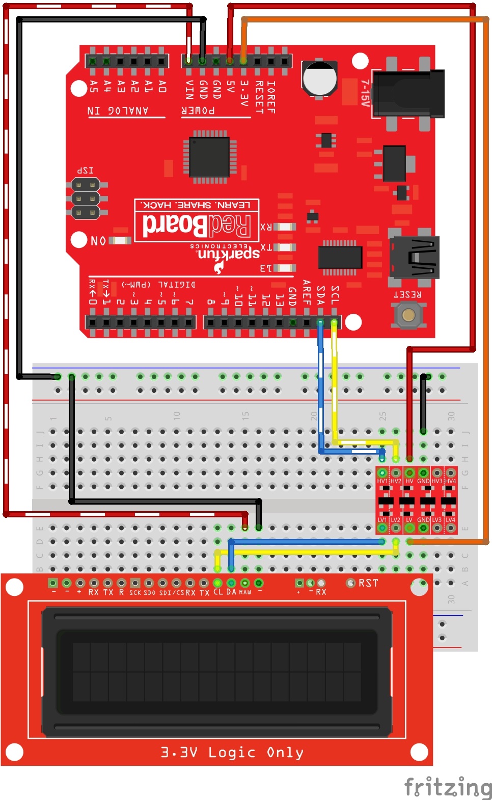
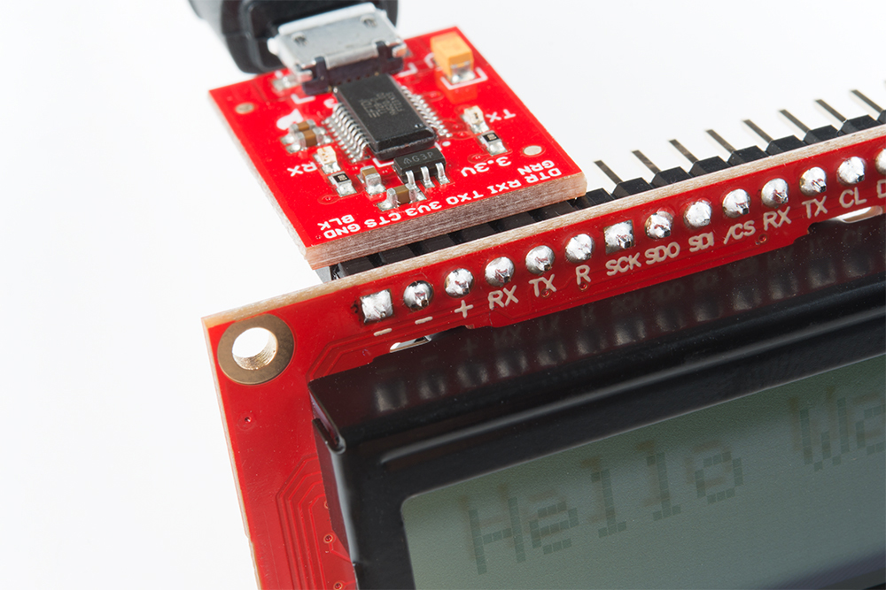
Using these screens, it is easy to connect to any microcontroller that has a serial UART, I2C, or SPI. If you are using Qwiic to control your screen, then all you need is a qwiic cable. However, if you choose to use something other than Qwiic (with connections located on the PTH headers), then please make sure you convert to 3.3V Logic! In the example below, we chose to use our 5V RedBoard with a Logic Level Converter.
The latest versions of the SerLCD have a qwiic connector on the back.
All Qwiic compatible products operate their I2C on the cable at a logic level of 3.3V, and so no conversion is necessary. Also note, the connector is a right-angled syle connector, so that if your project does not have much space on the back side of the screen, then you can exit your cable with a lower profile. We did not put it exiting on the edge of the board (as most Qwiic products do), so that if your project and/or enclosure is tight on the sides of the screen, the Qwiic cable will not conflict.
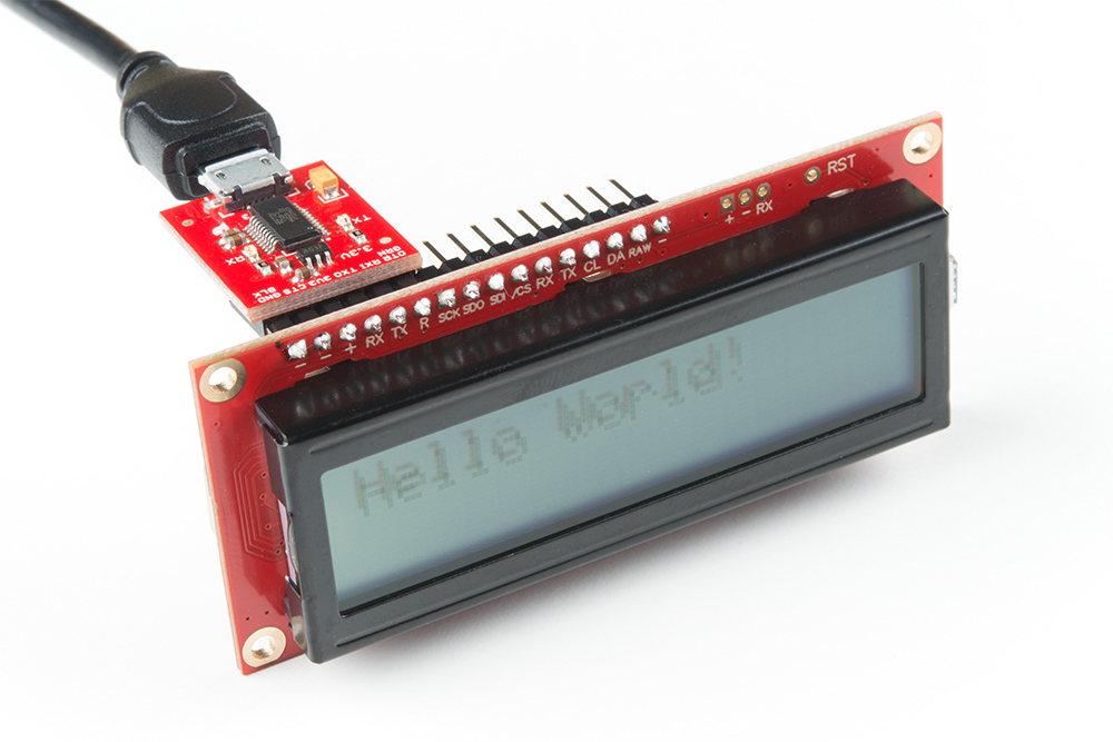
Both sizes of these screens (16x2 and 20x4) have a row of headers along the top side. This is where you can connect power and your choice of communication protocol (Serial UART, I2C, or SPI). It also has our 6-pin Arduino Serial port available for convenient firmware updates.
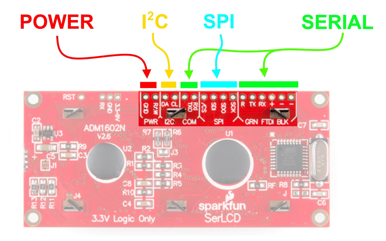
Note, if you choose Serial UART, there is a handy 3-pin JST footprint. This includes the minimum connections needed: RX, GND and VIN. Our JST Jumper 3 Wire Assembly is a good way to go:
 |
 |
| Location on screen | JST Jumper 3 Wire Assembly |
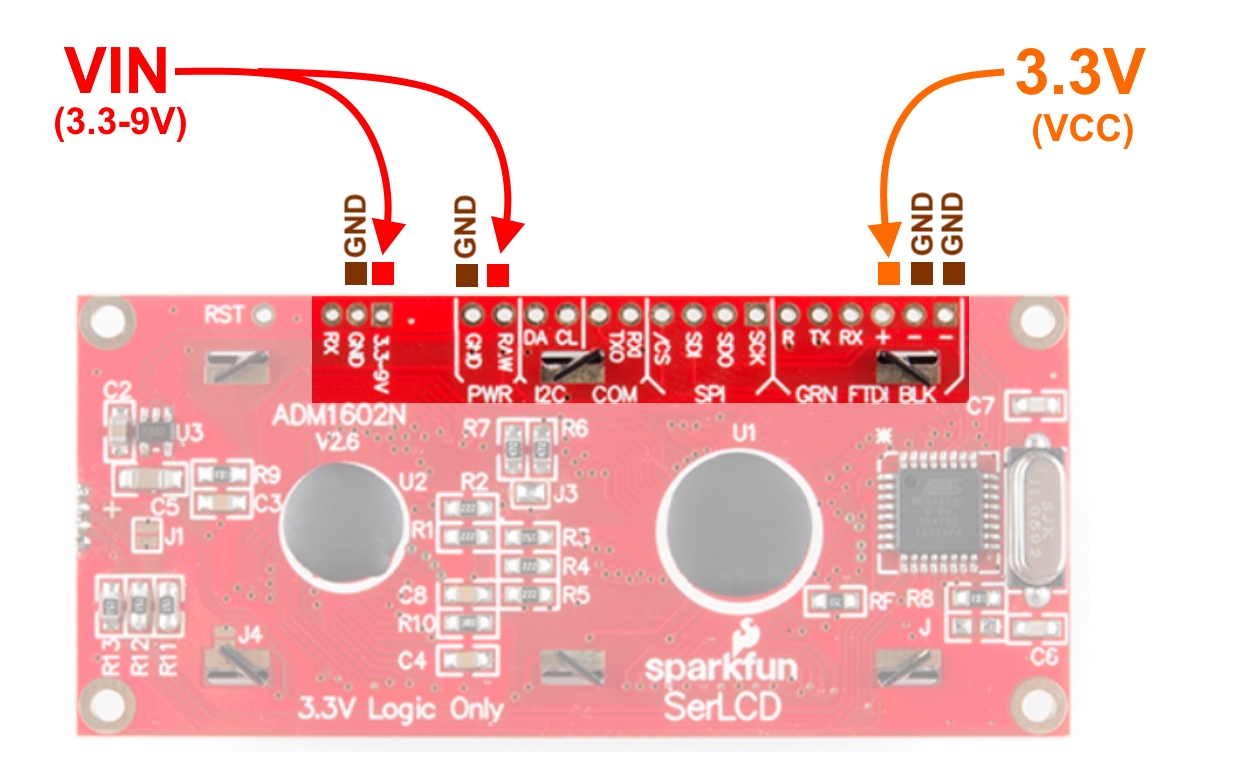
All of these screens can be powered by 3.3-9V. You have two pin options for connecting up power. One is labeled "RAW" and the other (on the 3-pin JST) is labeled "3.3-9V". Note, the pin labeled "+" is NOT a power input pin! This is connected to the VCC of the ATmega329P (3.3V).
Pro tip: If you plan to run 100% brightness on all three colors (red, green, blue), then it would be best to keep your power input voltage low. As close to 3.3V as possible is best. This will keep the on-board linear 3.3V voltage regulator nice and cool. It can accept up to 9V and power all three backlights at 100%, but it will get a little warm, and over years of use, potentially damage the vreg. For more information about vregs and why they heat up sometimes, please check out our tutorial: Power and Thermal Dissipation
The on-board ATmega328P controls the contrast of the screen using a PWM signal. This can be adjusted by sending a command via Serial UART, I2C, or SPI. The screens ship out with the contrast setting set to 10, which we have found works well for most environments. Temperature and supply voltage can affect the contrast of the LCD, so you may need to adjust it accordingly. For more info about contrast and a detailed example, please see the section below called: Serial UART: Example Code - Contrast Control with a Trimpot.
The following current measurements were taken from a basic multimeter. This assumes that:
5| 16x2 SerLCD w/ RGB Backlight Current Consumption |
||
| LED Color | no text | text |
|---|---|---|
| off | 4.4mA | 4.4mA |
| red | 11.9mA | 11.9mA |
| green | 8.9mA | 8.9mA |
| blue | 8.1mA | 8.1mA |
| white | 19.6mA | 19.6mA |
| cycling colors | 15.6mA | 15.6mA |
| 20.4 SerLCD w/ RGB Backlight Current Consumption |
||
| LED Color | no text | text |
|---|---|---|
| off | 4.5mA | 4.5mA |
| red | 21.6mA | 21.7mA |
| green | 17.2mA | 17.2mA |
| blue | 15.4mA | 15.5mA |
| white | 41.0mA | 41.1mA |
| cycling colors | 30.1mA | 30.8mA |
If you plan to mount a SerLCD into your project, please take a look at the following dimensional drawings. We have provided them in both PDF and PNG file format for both the 16x2 and the 20x4 Qwiic versions. Also, note that the tolerances of manufacturing are not always perfect, so please allow for some buffer room if designing around these numbers. Otherwise, your enclosure may be too tight or possibly not fit at all.
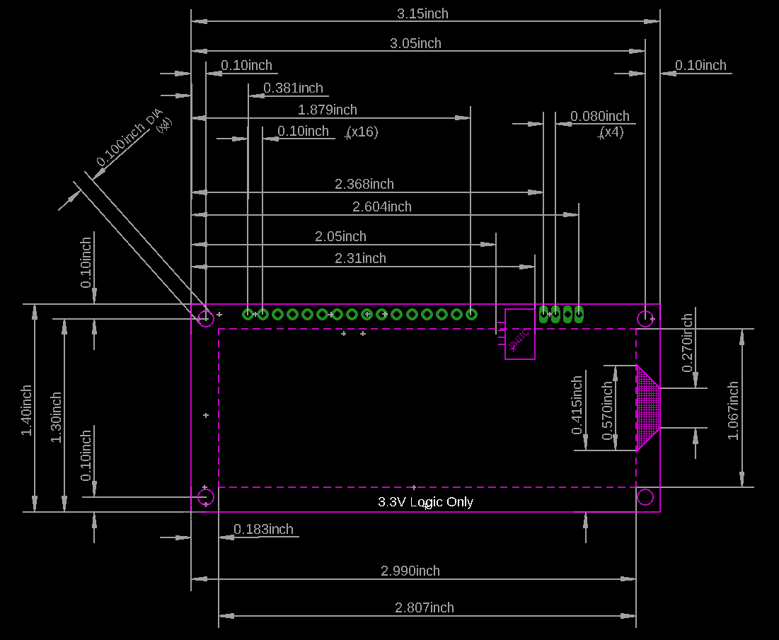
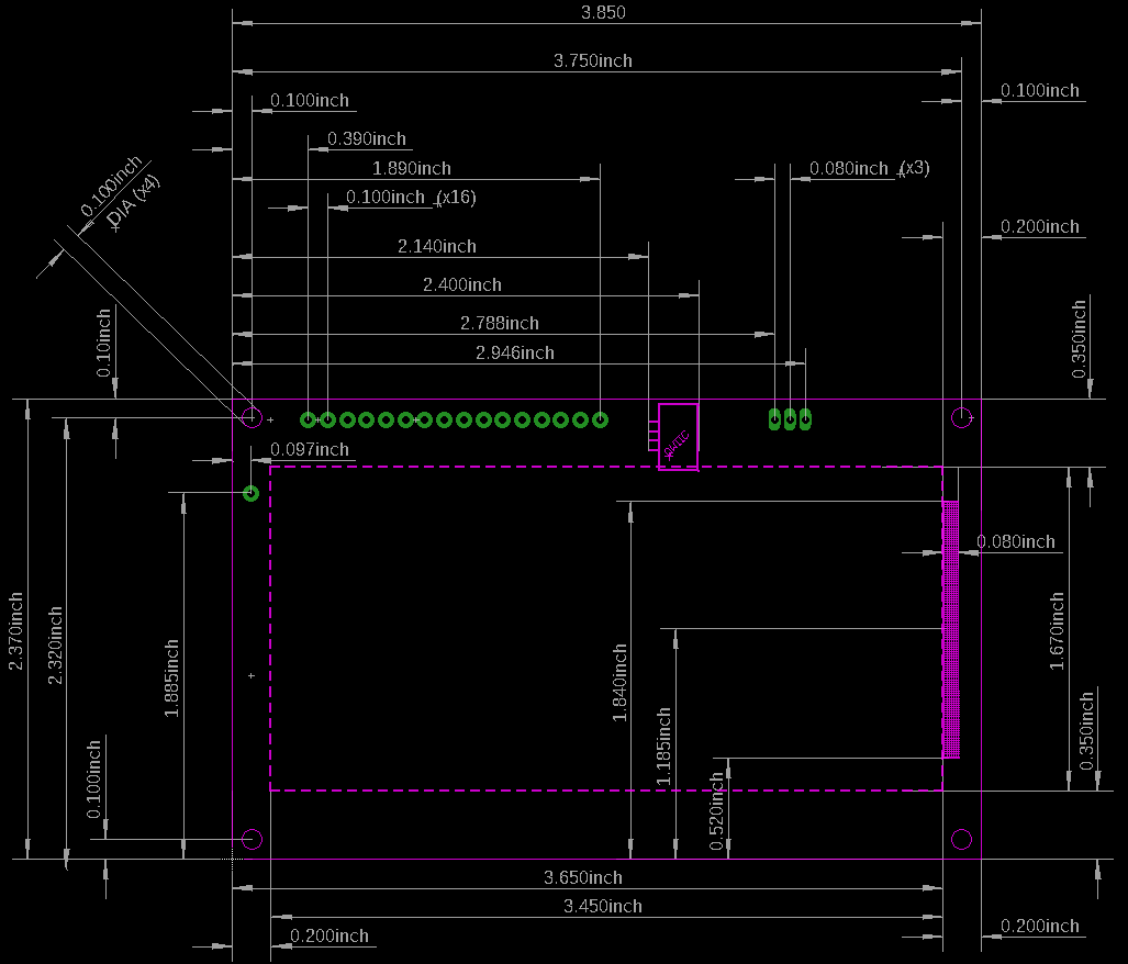
Also note, the standoff holes on these screens do not fit our 4-40 sized screws or hex metal standoffs. You will need to use something slightly smaller in diameter, like our 2-56 screws and metal nut.
If you would like to include an LCD as a device in your eagle design, then you will find the SparkFun-boards.lbr very useful. It is located in the larger github repository that contains all of the SparkFun Eagle Libraries.
Inside the library you will find the SER_LCD_QWIIC devices that allow you to simply drop this into your design and start netting/routing as desired!
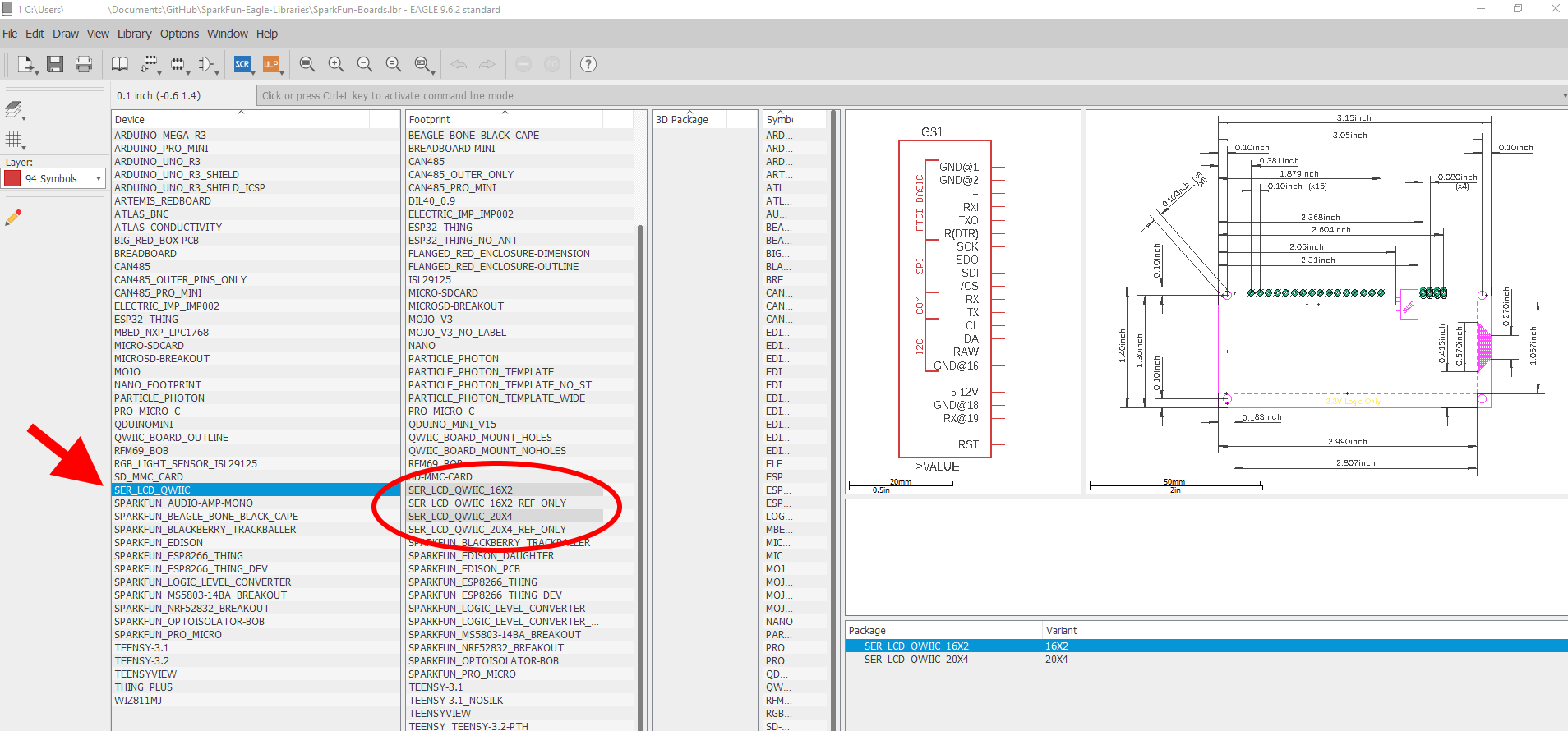
As another option, we have included footprints that have only the reference layers, with no electrical connections (that is, no device with a symbol and linked pins/pads).
") |
") |
| SER_LCD_QWIIC_16X2_REF_ONLY.fpt | SER_LCD_QWIIC_20X4_REF_ONLY.fpt |
These "reference only" footprints are useful for dropping into a design and then quickly knowing the location of your standoff holes, the screen, the qwiic connector and such. If you plan to use the qwiic connection, but still want to mount a SerLCD into your PCB design, the "reference only" footprints are the best option. You can add these as a part directly into your board editor, and you'll be ready to drop in standoff holes and start designing.
For this tutorial, we are going to try out Serial UART, I2C, and SPI. In order to easily follow along using a breadboard, solder some headers to the connection ports along the side of your screen. Also, solder some headers onto either side of the logic level converter. This will allow us to easily plug these into the breadboard and wire each data line up with jumper wires.
 |
 |
| Headers on screen | Headers on logic level converter |
Note, we are going to use the 16x2 model with RGB backlight during this tutorial. If you are using a different model (RGB text or the 20x4), then the header pin-out and spacing is identical.
The TX pin is used for Serial Uploads of new sketches onto your Arduino, and will cause problems for both your Arduino and the LCD. In other words, when you upload new code to your "project" Arduino, it will be confused because the screen is sharing that TX pin. Please only use software serial to control your LCD. For all of the Serial UART examples, we have setup software serial on D7.
For the first set of examples in this tutorial (SERIAL UART), there are three connections you need to make to the LCD: RX, GND, and RAW. For the other communication protocols that we will explore later, you will need to wire up some other lines. Please see the following Fritzing graphic to see how to wire up your connections through a logic level converter.
The SparkFun SerLCD Arduino library demonstrates all the bells and whistles of the SerLCD. The SparkFun SerLCD Arduino library can be downloaded with the Arduino library manager by searching 'SparkFun SerLCD' or you can grab the zip here from the GitHub repository:
Once you have the library installed checkout the various examples.
This SparkFun SerLCD Library really focuses on I2C because it's faster than serial and supports daisy-chaining. If you'd prefer serial, it's as simple as
lcd.begin(Serial);
Checkout the various examples to see the available functions to call for all the features but any and all can be used over serial, I2C, or SPI.
The easiest way to control the display is to use the SparkFun SerLCD Arduino Library. But if you prefer, you can connect using any device that can produce serial UART, I2C, or SPI.
The most basic way to use these screens is to simply send characters to them. They will display on the screen as you send them, and then if you go beyond the last character of the screen, it will begin overwriting from the first spot.
You can choose to send characters over Serial UART, I2C, or SPI. The best way to learn about each communication protocol is to try out the "basic" example located in the GitHub repository.
In addition to basic operation, there are special commands you can send the screen for special operations (like "clear screen" or set cursor position) and configuration settings (like BAUD RATE).
The special pipe character '|' (also called the 'or' character) is used to tell the screen to enter "settings mode". You then follow this command with another special character (usually "ctrl+c", ctrl+d, etc.). A complete table of commands are shown below in ASCII, DEC and HEX. Any one of these representations is acceptable when sending a command character.
The HD44780 LCD controller is very common. The extended commands for this chip include but are not limited to those described in table. Please refer to the HD44780 datasheet for more information.
Note, this "cheat sheet" is also located at the top of each example code section for easy reference.
| ASCII | DEC | HEX | Description |
|---|---|---|---|
| '|' | 124 | 0x7C | Enter Settings Mode. Note: When a second `|` ASCII character is sent to the display, the screen will escape the settings mode and display the same second vertical "pipe" as text. This feature is supported on v1.3+ of the SerLCD. |
| ctrl+h | 8 | 0x08 | Software reset of the system |
| ctrl+i | 9 | 0x09 | Enable/disable splash screen |
| ctrl+j | 10 | 0x0A | Save currently displayed text as splash |
| ctrl+k | 11 | 0x0B | Change baud to 2400bps |
| ctrl+l | 12 | 0x0C | Change baud to 4800bps |
| ctrl+m | 13 | 0x0D | Change baud to 9600bps |
| ctrl+n | 14 | 0x0E | Change baud to 14400bps |
| ctrl+o | 15 | 0x0F | Change baud to 19200bps |
| ctrl+p | 16 | 0x10 | Change baud to 38400bps |
| ctrl+q | 17 | 0x11 | Change baud to 57600bps |
| ctrl+r | 18 | 0x12 | Change baud to 115200bps |
| ctrl+s | 19 | 0x13 | Change baud to 230400bps |
| ctrl+t | 20 | 0x14 | Change baud to 460800bps |
| ctrl+u | 21 | 0x15 | Change baud to 921600bps |
| ctrl+v | 22 | 0x16 | Change baud to 1000000bps |
| ctrl+w | 23 | 0x17 | Change baud to 1200bps |
| ctrl+x | 24 | 0x18 | Change the contrast. Follow Ctrl+x with number 0 to 255. 40 is default. |
| ctrl+y | 25 | 0x19 | Change the TWI address. Follow Ctrl+y with number 0 to 255. 114 (0x72) is default. |
| ctrl+z | 26 | 0x1A | Enable/disable ignore RX pin on startup (ignore emergency reset) |
| ESC to '"' | 27-34 | 0x1B-0x22 | Record line of pixel data to a custom character. Up to eight characters can be recorded. Each character is made up of 7 lines of pixel data. Each line of pixel data must be proceeded by the character position to record within. 0x1B = character 0. 0x22 = character 7. For example, 0x1C 01 1C 03 1C 07 1C 0F 1C 1F 1C 3F 1C 7F will draw a triangle in character location 1. Saved to NVM. |
| '#' to '*' | 35-42 | 0x23-0x2A | Display custom character 0 through 7. For example, 0x24 will display the character stored in location 1. 0x28 will display character stored in location 5. |
| '+' | 43 | 0x2B | Set RGB Backlight. Follow this command with three bytes representing Red, Green, Blue, backlight values. Supported on v1.1+ of SerLCD. |
| ',' | 44 | 0x2C | Display current SerLCD firmware version. Supported on v1.1+ of SerLCD. If this command doesn't display anything version is v1.0. |
| '-' | 45 | 0x2D | Clear display. Move cursor to home position. |
| '.' | 46 | 0x2E | Enable system messages as settings change (ie, 'Contrast: 5'). Supported on v1.2+ of SerLCD. |
| '/' | 47 | 0x2F | Disable the displaying of system messages. Supported on v1.2+ of SerLCD. |
| '0' | 48 | 0x30 | Enable splash screen at power on. Similar to Ctrl+i command but definitive. Supported on v1.2+ of SerLCD. |
| '1' | 49 | 0x31 | Disable splash screen at power on. Similar to Ctrl+i command but definitive. Supported on v1.2+ of SerLCD. |
| n/a | 128-157 | 0x80-0x9D | Set the primary backlight brightness. 128 = Off, 157 = 100%. |
| n/a | 158-187 | 0x9E-0xBB | Set the green backlight brightness. 158 = Off, 187 = 100%. |
| n/a | 188-217 | 0xBC-0xD9 | Set the blue backlight brightness. 188 = Off, 217 = 100%. |
| ctrl+c to ctrl+g | 3-7 | 0x03-0x07 | Depricated command: Send line width. |
Clear display and set cursor position are the two commands that are used frequently. To clear the screen, send the control character '|' followed by '-'. Clearing the screen resets the cursor position back to position 0 (i.e. the first character on the first line).
Here's how you could do it doing a Serial UART write on software serial:
language:cpp
OpenLCD.write('|'); //Send setting character
OpenLCD.write('-'); //Send clear display character
Note, most of the example sketches in the repo use these two commands during setup(), so you can try any of the examples out to see these commands in action.
To set the active cursor position, send the control character 254 followed by 128 + row + position. To give this a shot, check out the complete example sketch in the GitHub repo or copy and paste the following into your Arduino IDE:
language:cpp
/*
 OpenLCD is an LCD with Serial/I2C/SPI interfaces.
 By: Nathan Seidle
 SparkFun Electronics
 Date: April 19th, 2015
 License: This code is public domain but you buy me a beer if you use this and we meet someday (Beerware license).

 OpenLCD gives the user multiple interfaces (serial, I2C, and SPI) to control an LCD. SerLCD was the original
 serial LCD from SparkFun that ran on the PIC 16F88 with only a serial interface and limited feature set.
 This is an updated serial LCD.

 This example shows how to change the position of the cursor. This is very important as this is the
 fastest way to update the screen, ie - rather than clearing the display and re-transmitting a handful of bytes
 a cursor move allows us to re-paint only what we need to update.

 We assume the module is currently at default 9600bps.

 We use software serial because if OpenLCD is attached to an Arduino's hardware serial port during bootloading
 it can cause problems for both devices.

 Note: If OpenLCD gets into an unknown state or you otherwise can't communicate with it send 18 (0x12 or ctrl+r)
 at 9600 baud while the splash screen is active and the unit will reset to 9600 baud.

 Emergency reset: If you get OpenLCD stuck into an unknown baud rate, unknown I2C address, etc, there is a
 safety mechanism built-in. Tie the RX pin to ground and power up OpenLCD. You should see the splash screen
 then "System reset Power cycle me" and the backlight will begin to blink. Now power down OpenLCD and remove
 the RX/GND jumper. OpenLCD is now reset to 9600bps with a I2C address of 0x72. Note: This feature can be
 disabled if necessary. See *Ignore Emergency Reset* for more information.

 To get this code to work, attached an OpenLCD to an Arduino Uno using the following pins:
 RX (OpenLCD) to Pin 7 (Arduino)
 VIN to 5V
 GND to GND

 Command cheat sheet:
 ASCII / DEC / HEX
 '|'    / 124 / 0x7C - Put into setting mode
 Ctrl+c / 3 / 0x03 - Change width to 20
 Ctrl+d / 4 / 0x04 - Change width to 16
 Ctrl+e / 5 / 0x05 - Change lines to 4
 Ctrl+f / 6 / 0x06 - Change lines to 2
 Ctrl+g / 7 / 0x07 - Change lines to 1
 Ctrl+h / 8 / 0x08 - Software reset of the system
 Ctrl+i / 9 / 0x09 - Enable/disable splash screen
 Ctrl+j / 10 / 0x0A - Save currently displayed text as splash
 Ctrl+k / 11 / 0x0B - Change baud to 2400bps
 Ctrl+l / 12 / 0x0C - Change baud to 4800bps
 Ctrl+m / 13 / 0x0D - Change baud to 9600bps
 Ctrl+n / 14 / 0x0E - Change baud to 14400bps
 Ctrl+o / 15 / 0x0F - Change baud to 19200bps
 Ctrl+p / 16 / 0x10 - Change baud to 38400bps
 Ctrl+q / 17 / 0x11 - Change baud to 57600bps
 Ctrl+r / 18 / 0x12 - Change baud to 115200bps
 Ctrl+s / 19 / 0x13 - Change baud to 230400bps
 Ctrl+t / 20 / 0x14 - Change baud to 460800bps
 Ctrl+u / 21 / 0x15 - Change baud to 921600bps
 Ctrl+v / 22 / 0x16 - Change baud to 1000000bps
 Ctrl+w / 23 / 0x17 - Change baud to 1200bps
 Ctrl+x / 24 / 0x18 - Change the contrast. Follow Ctrl+x with number 0 to 255. 120 is default.
 Ctrl+y / 25 / 0x19 - Change the TWI address. Follow Ctrl+x with number 0 to 255. 114 (0x72) is default.
 Ctrl+z / 26 / 0x1A - Enable/disable ignore RX pin on startup (ignore emergency reset)
 '-'    / 45 / 0x2D - Clear display. Move cursor to home position.
        / 128-157 / 0x80-0x9D - Set the primary backlight brightness. 128 = Off, 157 = 100%.
        / 158-187 / 0x9E-0xBB - Set the green backlight brightness. 158 = Off, 187 = 100%.
        / 188-217 / 0xBC-0xD9 - Set the blue backlight brightness. 188 = Off, 217 = 100%.

 For example, to change the baud rate to 115200 send 124 followed by 18.

*/

#include <SoftwareSerial.h>

SoftwareSerial OpenLCD(6, 7); //RX (not used), TX

int counter = 250;

void setup()
{
  Serial.begin(9600); //Start serial communication at 9600 for debug statements
  Serial.println("OpenLCD Example Code");

  OpenLCD.begin(115200); //Begin communication with OpenLCD

  //Send the reset command to the display - this forces the cursor to return to the beginning of the display
  OpenLCD.write('|'); //Send setting character
  OpenLCD.write('-'); //Send clear display character

  OpenLCD.print("Hello World!    Counter: "); //For 16x2 LCDs
  //OpenLCD.print("Hello World!        Counter: "); //For 20x4 LCDs
}

void loop()
{
  OpenLCD.write(254); //Send command character
  OpenLCD.write(128 + 64 + 9); //Change the position (128) of the cursor to 2nd row (64), position 9 (9)

  OpenLCD.print(counter++); //Re-print the counter
  //OpenLCD.print(" "); //When the counter wraps back to 0 it leaves artifacts on the display

  delay(2); //Hang out for a bit if we are running at 115200bps
}
The two lines of code that are actually changing the cursor position are as follows:
language:cpp
OpenLCD.write(254); //Send command character
OpenLCD.write(128 + 64 + 9); //Change the position (128) of the cursor to 2nd row (64), position 9 (9)
The example sets the cursor to the second row, position 9. To set the cursor to the first row, position 0, the command would look like this:
language:cpp
OpenLCD.write(254); //Send command character
OpenLCD.write(128 + 0 + 0); //Change the position (128) of the cursor to 1st row (0), position 0 (0)
Use the following tables to see row commands and available positions:
| 16 Character Displays | |
|---|---|
| Line Number (command) | Viewable Cursor Positions |
| 1 (0) | 0-15 |
| 2 (64) | 0-15 |
| 20 Character Displays | |
|---|---|
| Line Number (command) | Viewable Cursor Positions |
| 1 (0) | 0-19 |
| 2 (64) | 0-19 |
| 3 (20) | 0-19 |
| 4 (84) | 0-19 |
You should never need to send any screen size configuration commands to setup these screens. During setup(), the firmware looks at a specific pin that is either left floating or tied high. From this it can determine which screen size it is populated on (16x2 or 20x4). However, the commands are still available for manually setting the width and lines.
| ASCII | DEC | HEX | Description |
|---|---|---|---|
| '|' | 124 | 0x7C | Enter Settings Mode |
| ctrl+c | 3 | 0x03 | Change width to 20 |
| ctrl+d | 4 | 0x04 | Change width to 16 |
| ctrl+e | 5 | 0x05 | Change lines to 4 |
| ctrl+f | 6 | 0x06 | Change lines to 2 |
| ctrl+g | 7 | 0x07 | Change lines to 1 |
The screens ship out with a default baud rate setting to 9600 baud, but they can be set to a variety of baud rates. The 11.0592 MHz crystal provides greater clock accuracy and allows for baud rates up to 1MHz!
To change the baud rate, you will need to send two commands: First, send the "|" command to enter settings mode. Second, send the desired baud rate command. (For example, to set it to 57600, you'd send |, then Ctrl + q)
Here is a table will all of the available baud rate settings commands:
| ASCII | DEC | HEX | Description |
|---|---|---|---|
| '|' | 124 | 0x7C | Enter Settings Mode |
| ctrl+k | 11 | 0x0B | Change baud to 2400bps |
| ctrl+l | 12 | 0x0C | Change baud to 4800bps |
| ctrl+m | 13 | 0x0D | Change baud to 9600bps |
| ctrl+n | 14 | 0x0E | Change baud to 14400bps |
| ctrl+o | 15 | 0x0F | Change baud to 19200bps |
| ctrl+p | 16 | 0x10 | Change baud to 38400bps |
| ctrl+q | 17 | 0x11 | Change baud to 57600bps |
| ctrl+r | 18 | 0x12 | Change baud to 115200bps |
| ctrl+s | 19 | 0x13 | Change baud to 230400bps |
| ctrl+t | 20 | 0x14 | Change baud to 460800bps |
| ctrl+u | 21 | 0x15 | Change baud to 921600bps |
| ctrl+v | 22 | 0x16 | Change baud to 1000000bps |
If your screen enters into an unknown state or you otherwise can't communicate with it, try sending a Ctrl + r (0x12) character at 9600 baud while the splash screen is active (during the first 500 ms of boot-up) and the unit will reset to 9600 baud.
These screens provide you with control of the backlight to one of 30 different brightness levels on each of the colors (Red, Green and Blue). With this, you can mix colors together to get almost any custom color you'd like. This is also handy when power consumption of the unit must be minimized. By reducing the brightness, the overall backlight current consumption is reduced.
To change the backlight brightness, you will need to send two commands: First, send the "|" command to enter settings mode. Second, send a number that corresponds to the color and brightness you'd like to set. (For example, to set the Green backlight to 100%, you'd send |, then 187). For some good example code on how to adjust any and all of the colors, check out the example sketch here or copy and paste the code below into your Arduino IDE:
language:cpp
/*
 OpenLCD is an LCD with serial/I2C/SPI interfaces.
 By: Nathan Seidle
 SparkFun Electronics
 Date: April 19th, 2015
 License: This code is public domain but you buy me a beer if you use this and we meet someday (Beerware license).
 OpenLCD gives the user multiple interfaces (serial, I2C, and SPI) to control an LCD. SerLCD was the original
 serial LCD from SparkFun that ran on the PIC 16F88 with only a serial interface and limited feature set.
 This is an updated serial LCD.

 This example shows how to change the backlight brightness. We assume the module is currently at default 9600bps.
 We use software serial because if OpenLCD is attached to an Arduino's hardware serial port during bootloading
 it can cause problems for both devices.
 Note: If OpenLCD gets into an unknown state or you otherwise can't communicate with it send 18 (0x12 or ctrl+r)
 at 9600 baud while the splash screen is active and the unit will reset to 9600 baud.
 Emergency reset: If you get OpenLCD stuck into an unknown baud rate, unknown I2C address, etc, there is a
 safety mechanism built-in. Tie the RX pin to ground and power up OpenLCD. You should see the splash screen
 then "System reset Power cycle me" and the backlight will begin to blink. Now power down OpenLCD and remove
 the RX/GND jumper. OpenLCD is now reset to 9600bps with a I2C address of 0x72. Note: This feature can be
 disabled if necessary. See *Ignore Emergency Reset* for more information.
 To get this code to work, attached an OpenLCD to an Arduino Uno using the following pins:
 RX (OpenLCD) to Pin 7 (Arduino)
 VIN to 5V
 GND to GND

 Command cheat sheet:
 ASCII / DEC / HEX
 '|'    / 124 / 0x7C - Put into setting mode
 Ctrl+c / 3 / 0x03 - Change width to 20
 Ctrl+d / 4 / 0x04 - Change width to 16
 Ctrl+e / 5 / 0x05 - Change lines to 4
 Ctrl+f / 6 / 0x06 - Change lines to 2
 Ctrl+g / 7 / 0x07 - Change lines to 1
 Ctrl+h / 8 / 0x08 - Software reset of the system
 Ctrl+i / 9 / 0x09 - Enable/disable splash screen
 Ctrl+j / 10 / 0x0A - Save currently displayed text as splash
 Ctrl+k / 11 / 0x0B - Change baud to 2400bps
 Ctrl+l / 12 / 0x0C - Change baud to 4800bps
 Ctrl+m / 13 / 0x0D - Change baud to 9600bps
 Ctrl+n / 14 / 0x0E - Change baud to 14400bps
 Ctrl+o / 15 / 0x0F - Change baud to 19200bps
 Ctrl+p / 16 / 0x10 - Change baud to 38400bps
 Ctrl+q / 17 / 0x11 - Change baud to 57600bps
 Ctrl+r / 18 / 0x12 - Change baud to 115200bps
 Ctrl+s / 19 / 0x13 - Change baud to 230400bps
 Ctrl+t / 20 / 0x14 - Change baud to 460800bps
 Ctrl+u / 21 / 0x15 - Change baud to 921600bps
 Ctrl+v / 22 / 0x16 - Change baud to 1000000bps
 Ctrl+w / 23 / 0x17 - Change baud to 1200bps
 Ctrl+x / 24 / 0x18 - Change the contrast. Follow Ctrl+x with number 0 to 255. 120 is default.
 Ctrl+y / 25 / 0x19 - Change the TWI address. Follow Ctrl+x with number 0 to 255. 114 (0x72) is default.
 Ctrl+z / 26 / 0x1A - Enable/disable ignore RX pin on startup (ignore emergency reset)
 '-'    / 45 / 0x2D - Clear display. Move cursor to home position.
        / 128-157 / 0x80-0x9D - Set the primary backlight brightness. 128 = Off, 157 = 100%.
        / 158-187 / 0x9E-0xBB - Set the green backlight brightness. 158 = Off, 187 = 100%.
        / 188-217 / 0xBC-0xD9 - Set the blue backlight brightness. 188 = Off, 217 = 100%.

 For example, to change the baud rate to 115200 send 124 followed by 18.
*/

#include <SoftwareSerial.h>

SoftwareSerial OpenLCD(6, 7); //RX (not used), TX

byte counter = 0;

void setup()
{
  Serial.begin(9600); //Begin local communication for debug statements

  OpenLCD.begin(9600); //Begin communication with OpenLCD

  OpenLCD.write('|'); //Put LCD into setting mode
  OpenLCD.write(158 + 0); //Set green backlight amount to 0%

  OpenLCD.write('|'); //Put LCD into setting mode
  OpenLCD.write(188 + 0); //Set blue backlight amount to 0%
}

void loop()
{
  //Control red backlight
  Serial.println("Mono/Red backlight set to 0%");
  OpenLCD.write('|'); //Put LCD into setting mode
  OpenLCD.write(128); //Set white/red backlight amount to 0%

  delay(2000);

  //Control red backlight
  Serial.println("Mono/Red backlight set to 51%");
  OpenLCD.write('|'); //Put LCD into setting mode
  OpenLCD.write(128 + 15); //Set white/red backlight amount to 51%

  delay(2000);

  //Control red backlight
  Serial.println("Mono/Red backlight set to 100%");
  OpenLCD.write('|'); //Put LCD into setting mode
  OpenLCD.write(128 + 29); //Set white/red backlight amount to 100%

  delay(2000);

  //The following green and blue backlight control only apply if you have an RGB backlight enabled LCD

  all_off(); // turn off all backlights - see function below

  //Control green backlight
  Serial.println("Green backlight set to 51%");
  OpenLCD.write('|'); //Put LCD into setting mode
  OpenLCD.write(158 + 15); //Set green backlight amount to 51%

  delay(2000);

  //Control green backlight
  Serial.println("Green backlight set to 100%");
  OpenLCD.write('|'); //Put LCD into setting mode
  OpenLCD.write(158 + 29); //Set green backlight amount to 100%

  delay(2000);

  all_off(); // turn off all backlights - see function below

  //Control blue backlight
  Serial.println("Blue backlight set to 51%");
  OpenLCD.write('|'); //Put LCD into setting mode
  OpenLCD.write(188 + 15); //Set blue backlight amount to 51%

  delay(2000);

  //Control blue backlight
  Serial.println("Blue backlight set to 100%");
  OpenLCD.write('|'); //Put LCD into setting mode
  OpenLCD.write(188 + 29); //Set blue backlight amount to 100%

  delay(2000);

  all_off(); // turn off all backlights - see function below

}

void all_off(void)
{
  // Set all colors to 0

  OpenLCD.write('|'); //Put LCD into setting mode
  OpenLCD.write(128); //Set white/red backlight amount to 0%

  OpenLCD.write('|'); //Put LCD into setting mode
  OpenLCD.write(158 + 0); //Set green backlight amount to 0%

  OpenLCD.write('|'); //Put LCD into setting mode
  OpenLCD.write(188 + 0); //Set blue backlight amount to 0%

  delay(2000);
}
And here is a table showing all of the available backlight settings and commands:
| ASCII | DEC | HEX | Description |
|---|---|---|---|
| n/a | 128-157 | 0x80-0x9D | Set the primary backlight brightness. 128 = Off, 157 = 100%. |
| n/a | 158-187 | 0x9E-0xBB | Set the green backlight brightness. 158 = Off, 187 = 100%. |
| n/a | 188-217 | 0xBC-0xD9 | Set the blue backlight brightness. 188 = Off, 217 = 100%. |
These LCD screens have a splash screen by default that reads "SparkFun OpenLCD Baud:9600". This splash screen verifies that the unit is powered, working correctly, and that the connection to the LCD is correct. The splash screen is displayed for 500 ms during boot-up and may be turned off if desired.
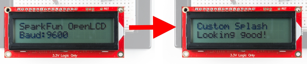
To make a custom splash screen, you need to send the characters you want to display (above we sent the characters "Custom Splash Looking good!") followed by |, then Ctrl + j). You will see a quick pop-up message display "Flash Recorded". Cycle power to test. You can also try out the example sketch located in the GitHub repo or copy and paste the code below into your Arduino IDE:
language:cpp
/*
 OpenLCD is an LCD with serial/I2C/SPI interfaces.
 By: Nathan Seidle, Pete Lewis
 SparkFun Electronics
 Date: 7/26/2018
 License: This code is public domain but you buy me a beer if you use this and we meet someday (Beerware license).
 OpenLCD gives the user multiple interfaces (serial, I2C, and SPI) to control an LCD. SerLCD was the original
 serial LCD from SparkFun that ran on the PIC 16F88 with only a serial interface and limited feature set.
 This is an updated serial LCD.

 This example shows how to change the Splash Screen contents. We assume the module is currently at default 9600bps.
 We use software serial because if OpenLCD is attached to an Arduino's hardware serial port during bootloading
 it can cause problems for both devices.
 Note: If OpenLCD gets into an unknown state or you otherwise can't communicate with it send 18 (0x12 or ctrl+r)
 at 9600 baud while the splash screen is active and the unit will reset to 9600 baud.
 Emergency reset: If you get OpenLCD stuck into an unknown baud rate, unknown I2C address, etc, there is a
 safety mechanism built-in. Tie the RX pin to ground and power up OpenLCD. You should see the splash screen
 then "System reset Power cycle me" and the backlight will begin to blink. Now power down OpenLCD and remove
 the RX/GND jumper. OpenLCD is now reset to 9600bps with a I2C address of 0x72. Note: This feature can be
 disabled if necessary. See *Ignore Emergency Reset* for more information.
 To get this code to work, attached an OpenLCD to an Arduino Uno using the following pins:
 RX (OpenLCD) to Pin 7 (Arduino)
 VIN to 5V
 GND to GND

 Command cheat sheet:
 ASCII / DEC / HEX
 '|'    / 124 / 0x7C - Put into setting mode
 Ctrl+c / 3 / 0x03 - Change width to 20
 Ctrl+d / 4 / 0x04 - Change width to 16
 Ctrl+e / 5 / 0x05 - Change lines to 4
 Ctrl+f / 6 / 0x06 - Change lines to 2
 Ctrl+g / 7 / 0x07 - Change lines to 1
 Ctrl+h / 8 / 0x08 - Software reset of the system
 Ctrl+i / 9 / 0x09 - Enable/disable splash screen
 Ctrl+j / 10 / 0x0A - Save currently displayed text as splash
 Ctrl+k / 11 / 0x0B - Change baud to 2400bps
 Ctrl+l / 12 / 0x0C - Change baud to 4800bps
 Ctrl+m / 13 / 0x0D - Change baud to 9600bps
 Ctrl+n / 14 / 0x0E - Change baud to 14400bps
 Ctrl+o / 15 / 0x0F - Change baud to 19200bps
 Ctrl+p / 16 / 0x10 - Change baud to 38400bps
 Ctrl+q / 17 / 0x11 - Change baud to 57600bps
 Ctrl+r / 18 / 0x12 - Change baud to 115200bps
 Ctrl+s / 19 / 0x13 - Change baud to 230400bps
 Ctrl+t / 20 / 0x14 - Change baud to 460800bps
 Ctrl+u / 21 / 0x15 - Change baud to 921600bps
 Ctrl+v / 22 / 0x16 - Change baud to 1000000bps
 Ctrl+w / 23 / 0x17 - Change baud to 1200bps
 Ctrl+x / 24 / 0x18 - Change the contrast. Follow Ctrl+x with number 0 to 255. 120 is default.
 Ctrl+y / 25 / 0x19 - Change the TWI address. Follow Ctrl+x with number 0 to 255. 114 (0x72) is default.
 Ctrl+z / 26 / 0x1A - Enable/disable ignore RX pin on startup (ignore emergency reset)
 '-'    / 45 / 0x2D - Clear display. Move cursor to home position.
        / 128-157 / 0x80-0x9D - Set the primary backlight brightness. 128 = Off, 157 = 100%.
        / 158-187 / 0x9E-0xBB - Set the green backlight brightness. 158 = Off, 187 = 100%.
        / 188-217 / 0xBC-0xD9 - Set the blue backlight brightness. 188 = Off, 217 = 100%.

 For example, to change the baud rate to 115200 send 124 followed by 18.
*/

#include <SoftwareSerial.h>

SoftwareSerial OpenLCD(6, 7); //RX (not used), TX

void setup()
{
  Serial.begin(9600); //Begin local communication for debug statements

  OpenLCD.begin(9600); //Begin communication with OpenLCD

  delay(1000);

  OpenLCD.write('|'); //Put LCD into setting mode
  OpenLCD.write('-'); // clear screen

  delay(1000);

  OpenLCD.print("Custom Splash   Looking good!"); // Send our new content to display - this will soon become our new splash screen.

  OpenLCD.write('|'); //Put LCD into setting mode
  OpenLCD.write(10); //Set current contents to splash screen memory (this is also a "ctrl-j", if you are doing it manually)

}

void loop()
{
  // nothing here, just doing this example in setup()
}
To disable the splash screen, send |, then Ctrl + i. Every time this command is sent to the unit, the splash screen display option will toggle. If the splash screen is currently being displayed, sending |, then Ctrl + i will disable the splash screen during the next boot, and sending |, then Ctrl + i characters again will enable the splash screen.
Here's how to setup your hardware for most of the Serial UART example code.
Note, some other examples require additional wiring (for example the contrast example requires a trimpot for variable control). We will show Fritzing graphics for each example covered in this tutorial. For the remaining tutorials, please look at the comments at the top of the example code for info on how to hookup the hardware.
You can download the latest example code for this experiment from the GitHub repo or you can copy and paste the following code into your Arduino IDE:
language:cpp
/*
 OpenLCD is an LCD with serial/I2C/SPI interfaces.
 By: Nathan Seidle
 SparkFun Electronics
 Date: April 19th, 2015
 License: This code is public domain but you buy me a beer if you use this and we meet someday (Beerware license).

 This example shows how to display a counter on the display over serial. We use software serial because if
 OpenLCD is attached to an Arduino's hardware serial port during bootloading  it can cause problems for both devices.

 To get this code to work, attached an OpenLCD to an Arduino Uno using the following pins:
 RX (OpenLCD) to Pin 7 (Arduino)
 VIN to 5V
 GND to GND

*/

#include <SoftwareSerial.h>

SoftwareSerial OpenLCD(6, 7); //RX, TX

byte counter = 0;
byte contrast = 2; //Lower is more contrast. 0 to 5 works for most displays.

void setup()
{
  Serial.begin(9600); //Start serial communication at 9600 for debug statements
  Serial.println("OpenLCD Example Code");

  OpenLCD.begin(9600); //Start communication with OpenLCD

  //Send contrast setting
  OpenLCD.write('|'); //Put LCD into setting mode
  OpenLCD.write(24); //Send contrast command
  OpenLCD.write(contrast);

}

void loop()
{
  //Send the clear command to the display - this returns the cursor to the beginning of the display
  OpenLCD.write('|'); //Setting character
  OpenLCD.write('-'); //Clear display

  OpenLCD.print("Hello World!    Counter: "); //For 16x2 LCD
  //OpenLCD.print("Hello World!        Counter: "); //For 20x4 LCD
  OpenLCD.print(counter++);

  delay(250); //Hang out for a bit
}
Here's what you should see after uploading the code to your Arduino. Try changing the text with a different message!
To send text to the board, wait 1/2 second (500ms) after power up for the splash screen to clear, then send text to the display through your serial port. The display understands all of the standard ASCII characters (upper and lowercase text, numbers, and punctuation), plus a number of graphic symbols and Japanese characters. See the HD44780 datasheet for the full list of supported characters.
If you send data that goes past the end of the first line, it will skip to the start of the second line. If you go past the end of the second line, the display will jump back up to the beginning of the first line.
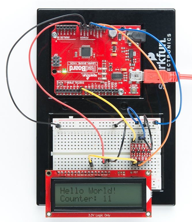
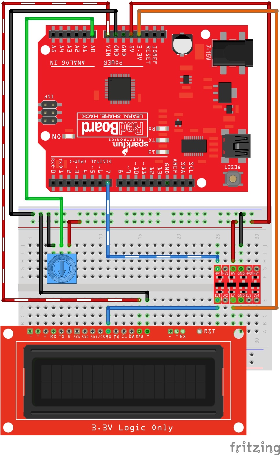
For this contrast control example, you will need to wire up a trimpot. This will allow you to adjust the contrast in real time and find the best setting for your environment. Wire things up like this:
You can download the latest example code for this experiment from the GitHub repo or you can copy and paste the following code into your Arduino IDE:
language:cpp
 /*
 OpenLCD is an LCD with Serial/I2C/SPI interfaces.
 By: Nathan Seidle
 SparkFun Electronics
 Date: April 19th, 2015
 License: This code is public domain but you buy me a beer if you use this and we meet someday (Beerware license).

 OpenLCD gives the user multiple interfaces (serial, I2C, and SPI) to control an LCD. SerLCD was the original
 serial LCD from SparkFun that ran on the PIC 16F88 with only a serial interface and limited feature set.
 This is an updated serial LCD.

 This example shows how to change the contrast using a trimpot. We assume the module is currently at
 default 9600bps.

 We use software serial because if OpenLCD is attached to an Arduino's hardware serial port during bootloading
 it can cause problems for both devices.

 Note: If OpenLCD gets into an unknown state or you otherwise can't communicate with it send 18 (0x12 or ctrl+r)
 at 9600 baud while the splash screen is active and the unit will reset to 9600 baud.

 Emergency reset: If you get OpenLCD stuck into an unknown baud rate, unknown I2C address, etc, there is a
 safety mechanism built-in. Tie the RX pin to ground and power up OpenLCD. You should see the splash screen
 then "System reset Power cycle me" and the backlight will begin to blink. Now power down OpenLCD and remove
 the RX/GND jumper. OpenLCD is now reset to 9600bps with a I2C address of 0x72. Note: This feature can be
 disabled if necessary. See *Ignore Emergency Reset* for more information.

 To get this code to work, attached an OpenLCD to an Arduino Uno using the following pins:
 RX (OpenLCD) to Pin 7 (Arduino)
 VIN to 5V
 GND to GND

 Hook a trimpot up:
 Pin 1 - 5V
 Pin 2 - A0
 Pin 3 - GND

*/

#include <SoftwareSerial.h>

SoftwareSerial OpenLCD(6, 7); //RX (not used), TX

byte counter = 0;

void setup()
{
  Serial.begin(9600); //Start serial communication at 9600 for debug statements
  Serial.println("OpenLCD Example Code");

  OpenLCD.begin(9600); //Begin communication with OpenLCD

  //Send the reset command to the display - this forces the cursor to return to the beginning of the display
  OpenLCD.write('|'); //Send setting character
  OpenLCD.write('-'); //Send clear display character
  OpenLCD.print("Contrast test");

  pinMode(A0, INPUT);
}

int oldContrast = 0;
long startTime = 0;
bool settingSent = false;

void loop()
{
  int trimpot = averageAnalogRead(A0);
  int newContrast = map(trimpot, 0, 1023, 0, 255); //Map this analog value down to 0-255

  //Only send new contrast setting to display if the user changes the trimpot
  if(newContrast != oldContrast)
  {
    Serial.print("nc: ");
    Serial.println(newContrast);

    oldContrast = newContrast; //Update

    startTime = millis();
    settingSent = false;
  }

  //Wait at least 100ms for user to stop turning trimpot
  //OpenLCD displays the contrast setting for around 2 seconds so we can't send constant updates
  if(millis() - startTime > 500 && settingSent == false)
  {
    //Send contrast setting
    OpenLCD.write('|'); //Put LCD into setting mode
    OpenLCD.write(24); //Send contrast command
    OpenLCD.write(newContrast);

    settingSent = true;

    Serial.print("New contrast: ");
    Serial.println(newContrast);
  }

  delay(100); //Hang out for a bit
}

//Takes an average of readings on a given pin
//Returns the average
int averageAnalogRead(byte pinToRead)
{
  byte numberOfReadings = 8;
  unsigned int runningValue = 0;

  for(int x = 0 ; x < numberOfReadings ; x++)
    runningValue += analogRead(pinToRead);
  runningValue /= numberOfReadings;

  return(runningValue);
}
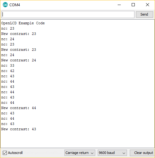
After uploading your sketch, you can now try adjusting the trimpot and watch the contrast change in real time. Here are a few examples that I see:
 |
 |
 |
| Contrast Setting: 0 | Contrast Setting: 55 | Contrast Setting: 80 |
Note, if you are not seeing any text in the LCD, make sure and try rotating to either extreme. If you are up above 100, then in some cases you may not see any text. Watching your serial monitor from your Arduino can be helpful as well. It will tell you the settings as you are sending them to the LCD. Here is some example serial debug that I see while I adjust the trimpot:
For this next example, you can use the same exact hardware setup as in the previous two examples (Serial Basic or Serial Contrast). To jump right in and start playing with backlight control, you can get the latest example code from the Github repo or you can copy and paste the following code into your Arduino IDE:
language:cpp
/*
 OpenLCD is an LCD with serial/I2C/SPI interfaces.
 By: Nathan Seidle
 SparkFun Electronics
 Date: April 19th, 2015
 License: This code is public domain but you buy me a beer if you use this and we meet someday (Beerware license).
 OpenLCD gives the user multiple interfaces (serial, I2C, and SPI) to control an LCD. SerLCD was the original
 serial LCD from SparkFun that ran on the PIC 16F88 with only a serial interface and limited feature set.
 This is an updated serial LCD.

 This example shows how to change the backlight brightness. We assume the module is currently at default 9600bps.
 We use software serial because if OpenLCD is attached to an Arduino's hardware serial port during bootloading
 it can cause problems for both devices.
 Note: If OpenLCD gets into an unknown state or you otherwise can't communicate with it send 18 (0x12 or ctrl+r)
 at 9600 baud while the splash screen is active and the unit will reset to 9600 baud.
 Emergency reset: If you get OpenLCD stuck into an unknown baud rate, unknown I2C address, etc, there is a
 safety mechanism built-in. Tie the RX pin to ground and power up OpenLCD. You should see the splash screen
 then "System reset Power cycle me" and the backlight will begin to blink. Now power down OpenLCD and remove
 the RX/GND jumper. OpenLCD is now reset to 9600bps with a I2C address of 0x72. Note: This feature can be
 disabled if necessary. See *Ignore Emergency Reset* for more information.
 To get this code to work, attached an OpenLCD to an Arduino Uno using the following pins:
 RX (OpenLCD) to Pin 7 (Arduino)
 VIN to 5V
 GND to GND

 Command cheat sheet:
 ASCII / DEC / HEX
 '|'    / 124 / 0x7C - Put into setting mode
 Ctrl+c / 3 / 0x03 - Change width to 20
 Ctrl+d / 4 / 0x04 - Change width to 16
 Ctrl+e / 5 / 0x05 - Change lines to 4
 Ctrl+f / 6 / 0x06 - Change lines to 2
 Ctrl+g / 7 / 0x07 - Change lines to 1
 Ctrl+h / 8 / 0x08 - Software reset of the system
 Ctrl+i / 9 / 0x09 - Enable/disable splash screen
 Ctrl+j / 10 / 0x0A - Save currently displayed text as splash
 Ctrl+k / 11 / 0x0B - Change baud to 2400bps
 Ctrl+l / 12 / 0x0C - Change baud to 4800bps
 Ctrl+m / 13 / 0x0D - Change baud to 9600bps
 Ctrl+n / 14 / 0x0E - Change baud to 14400bps
 Ctrl+o / 15 / 0x0F - Change baud to 19200bps
 Ctrl+p / 16 / 0x10 - Change baud to 38400bps
 Ctrl+q / 17 / 0x11 - Change baud to 57600bps
 Ctrl+r / 18 / 0x12 - Change baud to 115200bps
 Ctrl+s / 19 / 0x13 - Change baud to 230400bps
 Ctrl+t / 20 / 0x14 - Change baud to 460800bps
 Ctrl+u / 21 / 0x15 - Change baud to 921600bps
 Ctrl+v / 22 / 0x16 - Change baud to 1000000bps
 Ctrl+w / 23 / 0x17 - Change baud to 1200bps
 Ctrl+x / 24 / 0x18 - Change the contrast. Follow Ctrl+x with number 0 to 255. 120 is default.
 Ctrl+y / 25 / 0x19 - Change the TWI address. Follow Ctrl+x with number 0 to 255. 114 (0x72) is default.
 Ctrl+z / 26 / 0x1A - Enable/disable ignore RX pin on startup (ignore emergency reset)
 '-'    / 45 / 0x2D - Clear display. Move cursor to home position.
        / 128-157 / 0x80-0x9D - Set the primary backlight brightness. 128 = Off, 157 = 100%.
        / 158-187 / 0x9E-0xBB - Set the green backlight brightness. 158 = Off, 187 = 100%.
        / 188-217 / 0xBC-0xD9 - Set the blue backlight brightness. 188 = Off, 217 = 100%.

 For example, to change the baud rate to 115200 send 124 followed by 18.
*/

#include <SoftwareSerial.h>

SoftwareSerial OpenLCD(6, 7); //RX (not used), TX

byte counter = 0;

void setup()
{
  Serial.begin(9600); //Begin local communication for debug statements

  OpenLCD.begin(9600); //Begin communication with OpenLCD

  OpenLCD.write('|'); //Put LCD into setting mode
  OpenLCD.write(158 + 0); //Set green backlight amount to 0%

  OpenLCD.write('|'); //Put LCD into setting mode
  OpenLCD.write(188 + 0); //Set blue backlight amount to 0%
}

void loop()
{
  //Control red backlight
  Serial.println("Mono/Red backlight set to 0%");
  OpenLCD.write('|'); //Put LCD into setting mode
  OpenLCD.write(128); //Set white/red backlight amount to 0%

  delay(2000);

  //Control red backlight
  Serial.println("Mono/Red backlight set to 51%");
  OpenLCD.write('|'); //Put LCD into setting mode
  OpenLCD.write(128 + 15); //Set white/red backlight amount to 51%

  delay(2000);

  //Control red backlight
  Serial.println("Mono/Red backlight set to 100%");
  OpenLCD.write('|'); //Put LCD into setting mode
  OpenLCD.write(128 + 29); //Set white/red backlight amount to 100%

  delay(2000);

  //The following green and blue backlight control only apply if you have an RGB backlight enabled LCD

  all_off(); // turn off all backlights - see function below

  //Control green backlight
  Serial.println("Green backlight set to 51%");
  OpenLCD.write('|'); //Put LCD into setting mode
  OpenLCD.write(158 + 15); //Set green backlight amount to 51%

  delay(2000);

  //Control green backlight
  Serial.println("Green backlight set to 100%");
  OpenLCD.write('|'); //Put LCD into setting mode
  OpenLCD.write(158 + 29); //Set green backlight amount to 100%

  delay(2000);

  all_off(); // turn off all backlights - see function below

  //Control blue backlight
  Serial.println("Blue backlight set to 51%");
  OpenLCD.write('|'); //Put LCD into setting mode
  OpenLCD.write(188 + 15); //Set blue backlight amount to 51%

  delay(2000);

  //Control blue backlight
  Serial.println("Blue backlight set to 100%");
  OpenLCD.write('|'); //Put LCD into setting mode
  OpenLCD.write(188 + 29); //Set blue backlight amount to 100%

  delay(2000);

  all_off(); // turn off all backlights - see function below

}

void all_off(void)
{
  // Set all colors to 0

  OpenLCD.write('|'); //Put LCD into setting mode
  OpenLCD.write(128); //Set white/red backlight amount to 0%

  OpenLCD.write('|'); //Put LCD into setting mode
  OpenLCD.write(158 + 0); //Set green backlight amount to 0%

  OpenLCD.write('|'); //Put LCD into setting mode
  OpenLCD.write(188 + 0); //Set blue backlight amount to 0%

  delay(2000);
}
With this code running, you should see your backlight colors cycle through a pattern of 0%, then 50%, then 100%. It will show this for each color individually (Red, Green, and Blue). Here are some shots of what it looks like for me when I run the code. Note, yours may vary slightly due to your RAW input voltage and the temperature of your environment.
 |
 |
 |
 |
 |
 |
If you are using Qwiic, then you simply need to plug in a qwiic cable from your controller to your SerLCD. It helps to bend/curl your Qwiic cable a bit before inserting it into the right-angle connector on the SerLCD.
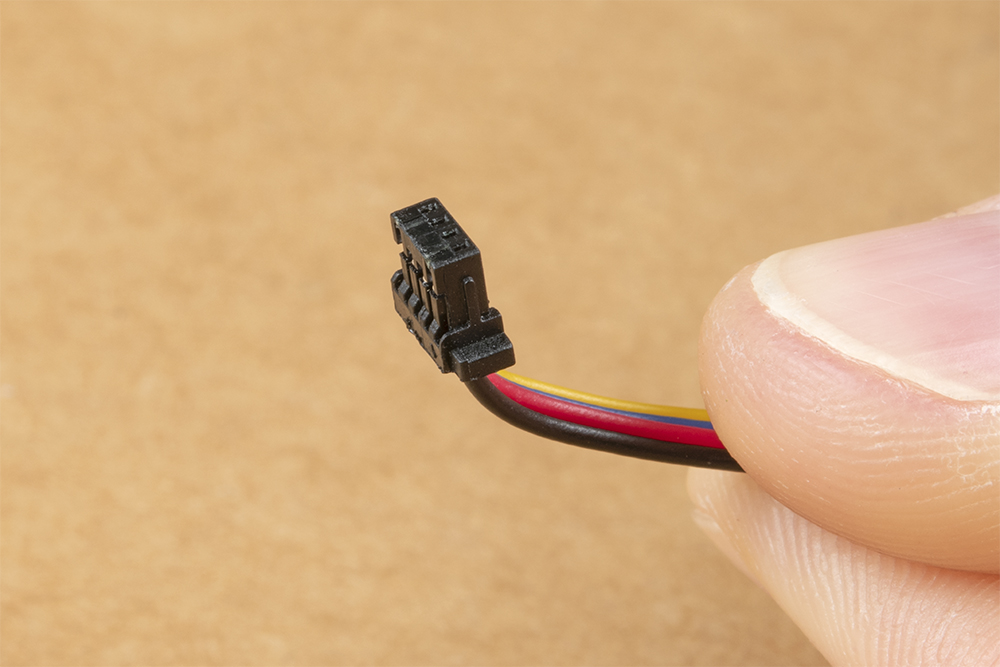
With the bend in place, you can better align it before inserting it all the way.

To avoid stressing the cable wires, it is best to push the Qwiic connector using your fingernails on the sides of the connector plastic. Tweezers can also do the trick.

Connect the other end of your Qwiic cable to you controller of choice, and you will be ready to go! Here we are showing the Redboard Qwiic:
For I2C, there are only 2 communication lines you need to connect: SDA and CLK. But remember, these must be 3.3V logic. So if you are using a 5V Redboard like we are, then you'll need to convert SDA and SCL from 5V to 3.3V. See the following Fritzing diagram for how you can wire this up:
After you've got your I2C lines wired up properly (via Qwiic or through logic level converter), you can get the latest example code from the GitHub repo or you can copy and paste the following code into your Arduino IDE:
language:cpp
/*
 OpenLCD is an LCD with Serial/I2C/SPI interfaces.
 By: Nathan Seidle
 SparkFun Electronics
 Date: April 19th, 2015
 License: This code is public domain but you buy me a beer if you use this and we meet someday (Beerware license).
 This is example code that shows how to send data over I2C to the display.
 Note: This code expects the display to be listening at the default I2C address. If your display is not at 0x72, you can
 do a hardware reset. Tie the RX pin to ground and power up OpenLCD. You should see the splash screen
 then "System reset Power cycle me" and the backlight will begin to blink. Now power down OpenLCD and remove
 the RX/GND jumper. OpenLCD is now reset.
 To get this code to work, attached an OpenLCD to an Arduino Uno using the following pins:
 SCL (OpenLCD) to A5 (Arduino)
 SDA to A4
 VIN to 5V
 GND to GND
 Command cheat sheet:
 ASCII / DEC / HEX
 '|'    / 124 / 0x7C - Put into setting mode
 Ctrl+c / 3 / 0x03 - Change width to 20
 Ctrl+d / 4 / 0x04 - Change width to 16
 Ctrl+e / 5 / 0x05 - Change lines to 4
 Ctrl+f / 6 / 0x06 - Change lines to 2
 Ctrl+g / 7 / 0x07 - Change lines to 1
 Ctrl+h / 8 / 0x08 - Software reset of the system
 Ctrl+i / 9 / 0x09 - Enable/disable splash screen
 Ctrl+j / 10 / 0x0A - Save currently displayed text as splash
 Ctrl+k / 11 / 0x0B - Change baud to 2400bps
 Ctrl+l / 12 / 0x0C - Change baud to 4800bps
 Ctrl+m / 13 / 0x0D - Change baud to 9600bps
 Ctrl+n / 14 / 0x0E - Change baud to 14400bps
 Ctrl+o / 15 / 0x0F - Change baud to 19200bps
 Ctrl+p / 16 / 0x10 - Change baud to 38400bps
 Ctrl+q / 17 / 0x11 - Change baud to 57600bps
 Ctrl+r / 18 / 0x12 - Change baud to 115200bps
 Ctrl+s / 19 / 0x13 - Change baud to 230400bps
 Ctrl+t / 20 / 0x14 - Change baud to 460800bps
 Ctrl+u / 21 / 0x15 - Change baud to 921600bps
 Ctrl+v / 22 / 0x16 - Change baud to 1000000bps
 Ctrl+w / 23 / 0x17 - Change baud to 1200bps
 Ctrl+x / 24 / 0x18 - Change the contrast. Follow Ctrl+x with number 0 to 255. 120 is default.
 Ctrl+y / 25 / 0x19 - Change the TWI address. Follow Ctrl+x with number 0 to 255. 114 (0x72) is default.
 Ctrl+z / 26 / 0x1A - Enable/disable ignore RX pin on startup (ignore emergency reset)
 '-'    / 45 / 0x2D - Clear display. Move cursor to home position.
        / 128-157 / 0x80-0x9D - Set the primary backlight brightness. 128 = Off, 157 = 100%.
        / 158-187 / 0x9E-0xBB - Set the green backlight brightness. 158 = Off, 187 = 100%.
        / 188-217 / 0xBC-0xD9 - Set the blue backlight brightness. 188 = Off, 217 = 100%.
 For example, to change the baud rate to 115200 send 124 followed by 18.
*/

#include <Wire.h>

#define DISPLAY_ADDRESS1 0x72 //This is the default address of the OpenLCD

int cycles = 0;

void setup()
{
  Wire.begin(); //Join the bus as master

  //By default .begin() will set I2C SCL to Standard Speed mode of 100kHz
  //Wire.setClock(400000); //Optional - set I2C SCL to High Speed Mode of 400kHz

  Serial.begin(9600); //Start serial communication at 9600 for debug statements
  Serial.println("OpenLCD Example Code");

  //Send the reset command to the display - this forces the cursor to return to the beginning of the display
  Wire.beginTransmission(DISPLAY_ADDRESS1);
  Wire.write('|'); //Put LCD into setting mode
  Wire.write('-'); //Send clear display command
  Wire.endTransmission();
}

void loop()
{
  cycles++; //Counting cycles! Yay!
  //  Serial.print("Cycle: "); //These serial.print statements take multiple miliseconds
  //  Serial.println(cycles);

  i2cSendValue(cycles); //Send the four characters to the display

  delay(50); //The maximum update rate of OpenLCD is about 100Hz (10ms). A smaller delay will cause flicker
}

//Given a number, i2cSendValue chops up an integer into four values and sends them out over I2C
void i2cSendValue(int value)
{
  Wire.beginTransmission(DISPLAY_ADDRESS1); // transmit to device #1

  Wire.write('|'); //Put LCD into setting mode
  Wire.write('-'); //Send clear display command

  Wire.print("Cycles: ");
  Wire.print(value);

  Wire.endTransmission(); //Stop I2C transmission
}
You may notice that this is very similar to the example above, Serial Basic. Well, that's because it is doing the exact same thing but instead of Serial UART communication, it is sending the commands over I2C. If you've got it wired up correctly and the example code running, then you should see the "Hello World Counter:XX" displaying in your LCD screen.
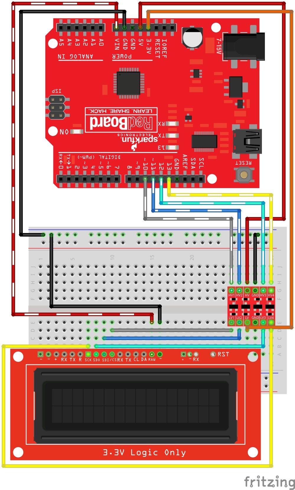
Here's how to wire up your RedBoard to talk SPI to your LCD screen. Remember, convert those logic levels to 3.3Vs! Also note, you could choose a different output pin for the csPin, but in this example we are using D10.
With your hardware now hooked up, the following code is the SPI basic example - it simply writes some characters to the screen over SPI. It has a counter that will increment on each cycle of your main loop. It clears the screen at the top of each loop, so you simply see "Cycles: 1", "Cycles: 2" and so on.
delay(5)) between the clear command ('-') and sending a string in order for the string to display properly. .
.
.
//Send the clear display command to the display - this forces the cursor to return to the beginning of the display
digitalWrite(csPin, LOW); //Drive the CS pin low to select OpenLCD
SPI.transfer('|'); //Put LCD into setting mode
SPI.transfer('-'); //Send clear display command
delay(10); //<==== add slight delay here
digitalWrite(csPin, HIGH); //Release the CS pin to de-select OpenLCDYou can get the latest example code from the GitHub repo or you can copy and paste the following code into your Arduino IDE:
language:cpp
/*
 OpenLCD is an LCD with Serial/I2C/SPI interfaces.
 By: Nathan Seidle
 SparkFun Electronics
 Date: April 19th, 2015
 License: This code is public domain but you buy me a beer if you use this and we meet someday (Beerware license).

 This is example code that shows how to send data over SPI to the display.

 To get this code to work, attached an OpenLCD to an Arduino Uno using the following pins:
 CS (OpenLCD) to 10 (Arduino)
 SDI to 11
 SDO to 12 (optional)
 SCK to 13
 VIN to 5V
 GND to GND

 Command cheat sheet:
 ASCII / DEC / HEX
 '|'    / 124 / 0x7C - Put into setting mode
 Ctrl+c / 3 / 0x03 - Change width to 20
 Ctrl+d / 4 / 0x04 - Change width to 16
 Ctrl+e / 5 / 0x05 - Change lines to 4
 Ctrl+f / 6 / 0x06 - Change lines to 2
 Ctrl+g / 7 / 0x07 - Change lines to 1
 Ctrl+h / 8 / 0x08 - Software reset of the system
 Ctrl+i / 9 / 0x09 - Enable/disable splash screen
 Ctrl+j / 10 / 0x0A - Save currently displayed text as splash
 Ctrl+k / 11 / 0x0B - Change baud to 2400bps
 Ctrl+l / 12 / 0x0C - Change baud to 4800bps
 Ctrl+m / 13 / 0x0D - Change baud to 9600bps
 Ctrl+n / 14 / 0x0E - Change baud to 14400bps
 Ctrl+o / 15 / 0x0F - Change baud to 19200bps
 Ctrl+p / 16 / 0x10 - Change baud to 38400bps
 Ctrl+q / 17 / 0x11 - Change baud to 57600bps
 Ctrl+r / 18 / 0x12 - Change baud to 115200bps
 Ctrl+s / 19 / 0x13 - Change baud to 230400bps
 Ctrl+t / 20 / 0x14 - Change baud to 460800bps
 Ctrl+u / 21 / 0x15 - Change baud to 921600bps
 Ctrl+v / 22 / 0x16 - Change baud to 1000000bps
 Ctrl+w / 23 / 0x17 - Change baud to 1200bps
 Ctrl+x / 24 / 0x18 - Change the contrast. Follow Ctrl+x with number 0 to 255. 120 is default.
 Ctrl+y / 25 / 0x19 - Change the TWI address. Follow Ctrl+x with number 0 to 255. 114 (0x72) is default.
 Ctrl+z / 26 / 0x1A - Enable/disable ignore RX pin on startup (ignore emergency reset)
 '-'    / 45 / 0x2D - Clear display. Move cursor to home position.
        / 128-157 / 0x80-0x9D - Set the primary backlight brightness. 128 = Off, 157 = 100%.
        / 158-187 / 0x9E-0xBB - Set the green backlight brightness. 158 = Off, 187 = 100%.
        / 188-217 / 0xBC-0xD9 - Set the blue backlight brightness. 188 = Off, 217 = 100%.

 For example, to change the baud rate to 115200 send 124 followed by 18.
*/

#include <SPI.h>

int csPin = 10; //You can use any output pin but for this example we use 10

int cycles = 0;

void setup()
{
  pinMode(csPin, OUTPUT);
  digitalWrite(csPin, HIGH); //By default, don't be selecting OpenLCD

  SPI.begin(); //Start SPI communication
  //SPI.beginTransaction(SPISettings(100000, MSBFIRST, SPI_MODE0));
  SPI.setClockDivider(SPI_CLOCK_DIV128); //Slow down the master a bit
}

void loop()
{
  cycles++; //Counting cycles! Yay!

  //Send the clear display command to the display - this forces the cursor to return to the beginning of the display
  digitalWrite(csPin, LOW); //Drive the CS pin low to select OpenLCD
  SPI.transfer('|'); //Put LCD into setting mode
  SPI.transfer('-'); //Send clear display command
  digitalWrite(csPin, HIGH); //Release the CS pin to de-select OpenLCD

  char tempString[50]; //Needs to be large enough to hold the entire string with up to 5 digits
  sprintf(tempString, "Cycles: %d", cycles);
  spiSendString(tempString);

  //25ms works well
  //15ms slight flickering
  //5ms causes flickering
  delay(250);
}

//Sends a string over SPI
void spiSendString(char* data)
{
  digitalWrite(csPin, LOW); //Drive the CS pin low to select OpenLCD
  for(byte x = 0 ; data[x] != '\0' ; x++) //Send chars until we hit the end of the string
    SPI.transfer(data[x]);
  digitalWrite(csPin, HIGH); //Release the CS pin to de-select OpenLCD
}
If the display is powered up without the RX line connected to anything, the display may fill with strange characters. This is because the display is receiving random noise on the disconnected line. If you connect the RX line to a true TX port, this will not happen.
If the display is unreadable or washed out, the contrast may need to be adjusted. This is done in software, so you will need to send your display some contrast control commands via Serial UART, I2C or SPI. There is a specific example for each of these communication types inside the github repository here:
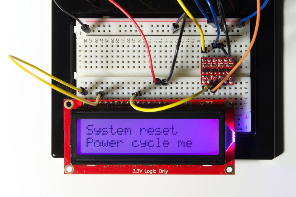
If your LCD screen has entered an unknown state, or you are unable to communicate with it, it's probably a good idea to try resetting everything back to default settings. The OpenLCD firmware has a built-in "emergency reset" feature. When the screen first boots up, the AVR on the back will watch its RX pin. If that pin is held LOW (aka tied to ground), for 2 seconds, then it will reset all settings to default. Most importantly, your baud rate will be set back to 9600. After the reset is complete, the screen will display the message "System Reset Power Cycle Me", and flicker the backlight on and off repeatedly until you cycle power.
To perform an emergency reset, please be sure to follow these exact steps in this order:
Now, please enjoy your default settings (including 9600 baud).
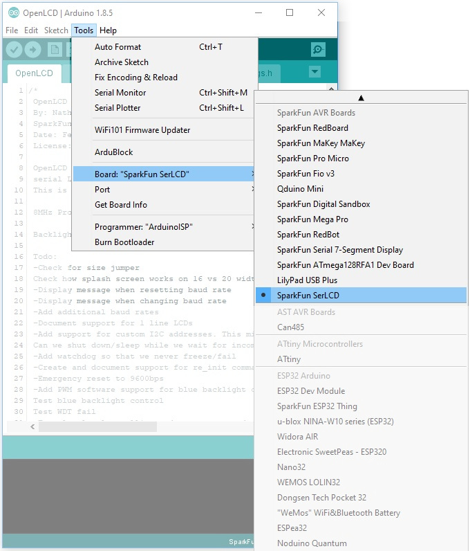
To update the firmware on your LCD, you can use an FTDI Basic 3.3V - beefy model and the Arduino IDE software. The AVR on the back of your LCD actually has an Arduino-compatible bootloader. That said, it is slightly custom in that it was compiled for the 11.0592 crystal. This means you will need to install the SparkFun AVR Boards, and then select "Sparkfun SerLCD" as your board type.
If you've made it this far, presumably you have the latest version of the Arduino IDE on your desktop. If you do not, please review our tutorial on installing the Arduino IDE for board add-ons. Here's the tutorial for installing custom board packages:
Once you have that installed, you should see "SparkFun SerLCD" as a board option from the drop down menu here:
Now plug in your serial FTDI basic into your LCD screen.
Make sure to line it up properly so the "-" is lined up withe the "GND", and the "R" is lined up with "DTR".
| AVR Programmer Pins | SerLCD Pins | External Power Source for Target (assuming the AVR Programmer is not able to power the target) |
| RAW | 5V | |
| Vcc | Vcc | |
| GND | GND | GND |
| COPI | SDI | |
| CIPO | SDO | |
| SCK | SCK | |
| RESET | RST |
Download and unzip the latest firmware located in the OpenLCD GitHub repository:
Not that you will need to include all of the files in the "... > OpenLCD-master > firmware > OpenLCD" directory. When you open the OpenLCD.ino sketch in arduino, the other necessary files will open as tabs.
You will also need to install the SoftPWM and LiquidCrystalFast libraries. You will need to download and manually install the libraries the following libraries before you are able to upload the default firmware. To use these libraries, you can add the library from the Arduino IDE by selecting Sketch > Include Library > Add .ZIP Library… and selecting the .zip file from wherever you store your file downloads.
Once the board add-on and associated libraries are installed, click the UPLOAD button in the IDE (the right facing arrow) to get the latest code onto your LCD!
If you are using the serial enabled LCD with an Atmega32U4-based Arduino (like a Pro Micro, Arduino Leonardo, Arduino LilyPad USB, etc), you might need to add a small delay in the setup before you can get it working with the hardware UART (pins 0 and 1). Here's an example:
language:cpp
///test example using ATmega32U4's hardware UART and delay
void setup() {
  delay(2000);//add delay so the ATmega32U4 can have a second before sending serial data to the LCD
  Serial1.begin(9600);//set up the hardware UART baud
}

void loop() {
  Serial1.print("print something");//send something to the serial enabled LCD
  delay(50);
}
Unfortunately, you are not able to use the serial enabled LCDs with an Arduino Due due the differences in how change interrupts are used for the ARM processor. The software serial library is not included in the Arduino Due's tree:
Try using the other hardware serial UARTs that are not connected to the Arduino Due's programming pins for uploading. Make sure to adjust the code for the hardware serial UART.
Now that you've successfully got your OpenLCD up and running, it's time to incorporate it into your own project! When it is complete (or even during the design and build phases) please share in comments section of this tutorial, we'd love to hear about it! We also like doing project highlights, so please don't hesitate to reach out when it's finished. Maybe we could even feature your project with a blog post and video!
Also, if you ran into any issues during this hookup guide, or something wasn't crystal clear the first time you read it, please let us know in the comments section of this tutorial. We strive to make the best documentation possible, and really want to hear about any pain points you discovered. Thanks in advance!
For more information, check out the resources below:
This tutorial focuses on using the SerLCD with Arduino. To use the SerLCD on a Raspberry Pi with Python, check out the Qwiic SHIM Kit Hookup Guide for Raspberry Pi for more information.
Need some inspiration for your next project? Check out some of these related tutorials:
learn.sparkfun.com | CC BY-SA 3.0 | SparkFun Electronics | Niwot, Colorado