APA102 Addressable LED Hookup Guide
 bboyho
 Introduction
The APA102C addressable LEDs employ a 2-wire communication protocol consisting of a clock and data line. While this requires one more wire than standard WS2812 addressable LEDs, the advantage is that the communication with the LEDs have a faster data and refresh rates (great for persistence of vision (a.k.a. POV) projects). They are not as strict with timing compared to the WS2812's.
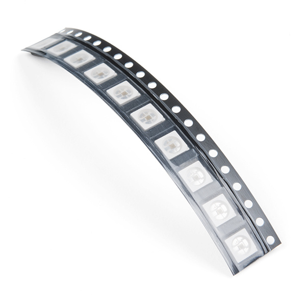
SMD LED - RGB APA102C-5050 (Pack of 10)
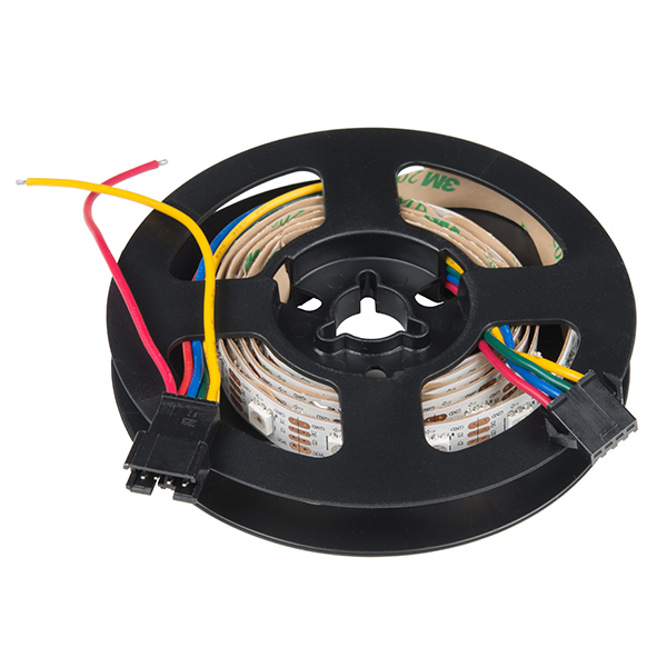
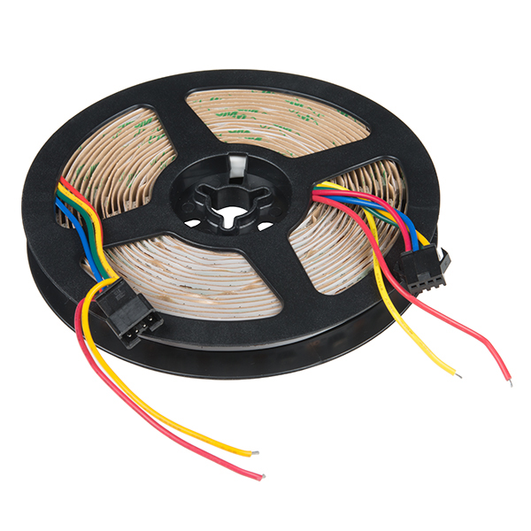
COM-14863LED Strips
LED strips can come in sealed and unsealed versions. The SparkFun catalog carries the APA102's in 1M bare and 5M bare strips.
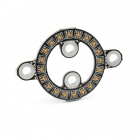
Matrices, Rings, Sticks, Shields
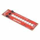
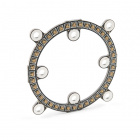
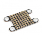
Depending on the project, they can also be populated on PCBs as a matrix, ring, or stick. These can be useful for marquees or adding unique animations to your project! There are different sizes of APA102's.
Required Materials
To follow along with this tutorial, you will need the following materials. You may not need everything though depending on what you have. Add it to your cart, read through the guide, and adjust the cart as necessary.
APA102-Based LED Board or Strip
Stating the obvious: you'll need a APA102-based board or strip. The more the merrier! In the example hookup, we'll be using a 1M LED strip, but the example should be adaptable to the other APA102-based products. Grab however many you think you'll need for your project, regardless of how many you have, it's not enough.
Microcontroller or Single Board Computer?
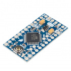
To get started, you're going to need a microcontroller or a single board computer. Something that can send the series of 1's and 0's used to control the LEDs. Our go-to is the classic Arduino Uno with the ATmega328P, but any Arduino board that is supported with the library should do. A Teensy, ESP8266, ESP32, or Raspberry Pi can work as well but for the scope of this tutorial, we will be using a 5V Arduino populated with an ATmega328P, the SparkFun RedBoard Qwiic.

Logic Level
The APA102C addressable LEDs operate natively with 5V logic, so it will save you trouble to choose a controller that can give you 0-5V, but it can be made to work with 3.3V logic with the use of a level translator. If you are using a 5V microcontroller, you will not need the following.

Power Supply
You will also need a 5V power supply to run your controller and new lights. Each APA102C can draw as much as 60mA when red, green and blue are all full-on, so you'll want to have something a little beefy. For testing purposes (assuming that you do not turn all the LEDs fully on), you can use a computer's USB port and cable. A wall adapter capable of 2.5A should be plenty for our demonstration if you are placing it in an installation. If you've got a bigger project in mind, check out the Mean Well 5V/20A supply.
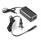
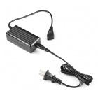
Power Supply - 12V/5V (2A)
TOL-15664Wires
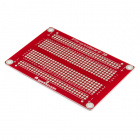
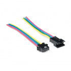
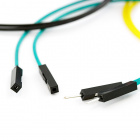
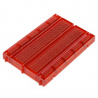
You'll also need some way to connect the boards and an Arduino. If you are using a breakout board or pieces of the LED strip, you could use a combination of jumper wires (such as M/M or M/F) and breadboard (solderless or solderable). Or you could just go with a few pieces of hookup wire or 4-pin JST-SM pigtail connectors.
Tools
Lastly, you are going to need a few tools. A soldering iron, some solder, general soldering accessories, wire, and a wire stripper should do if you are modifying the LED strip or connecting to a breakout board.


Suggested Reading
We're tried to make this hookup guide as simple as possible, but you may be lacking some basic information that could help your understanding as we go forward. For more info, check out these tutorials.