APA102 Addressable LED Hookup Guide
Introduction
The APA102C addressable LEDs employ a 2-wire communication protocol consisting of a clock and data line. While this requires one more wire than standard WS2812 addressable LEDs, the advantage is that the communication with the LEDs have a faster data and refresh rates (great for persistence of vision (a.k.a. POV) projects). They are not as strict with timing compared to the WS2812's.
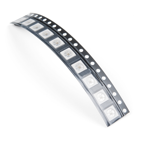
SMD LED - RGB APA102C-5050 (Pack of 10)
COM-14863LED Strips
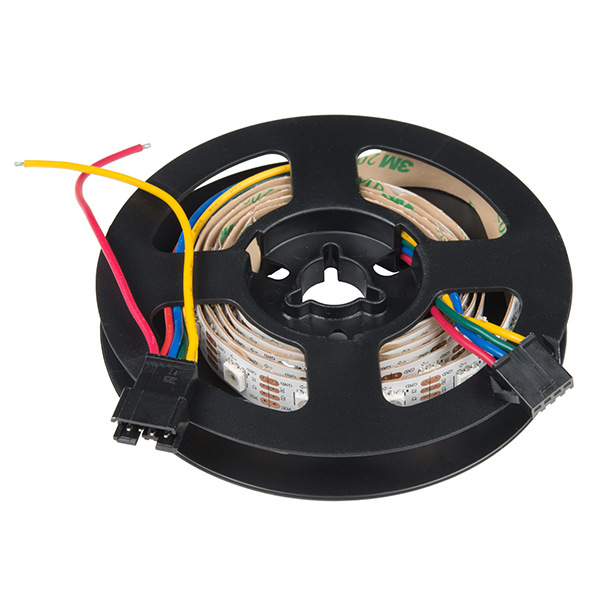
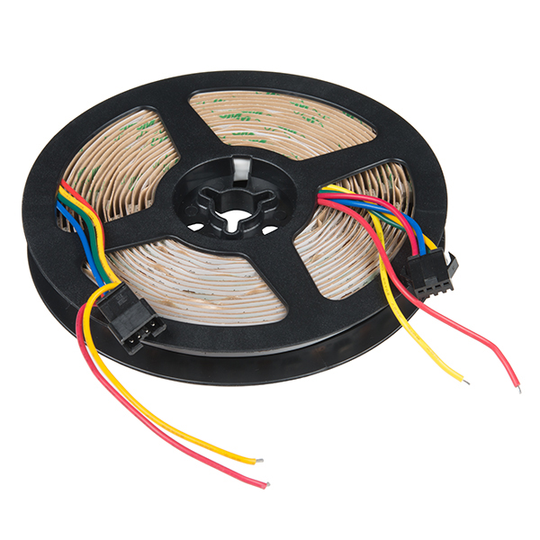
LED strips can come in sealed and unsealed versions. The SparkFun catalog carries the APA102's in 1M bare and 5M bare strips.
Matrices, Rings, Sticks, Shields
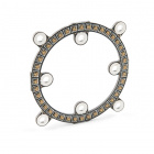
Depending on the project, they can also be populated on PCBs as a matrix, ring, or stick. These can be useful for marquees or adding unique animations to your project! There are different sizes of APA102's.
Required Materials
To follow along with this tutorial, you will need the following materials. You may not need everything though depending on what you have. Add it to your cart, read through the guide, and adjust the cart as necessary.
APA102-Based LED Board or Strip
Stating the obvious: you'll need a APA102-based board or strip. The more the merrier! In the example hookup, we'll be using a 1M LED strip, but the example should be adaptable to the other APA102-based products. Grab however many you think you'll need for your project, regardless of how many you have, it's not enough.
Microcontroller or Single Board Computer?
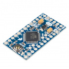
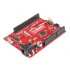
To get started, you're going to need a microcontroller or a single board computer. Something that can send the series of 1's and 0's used to control the LEDs. Our go-to is the classic Arduino Uno with the ATmega328P, but any Arduino board that is supported with the library should do. A Teensy, ESP8266, ESP32, or Raspberry Pi can work as well but for the scope of this tutorial, we will be using a 5V Arduino populated with an ATmega328P, the SparkFun RedBoard Qwiic.
Logic Level
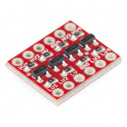
The APA102C addressable LEDs operate natively with 5V logic, so it will save you trouble to choose a controller that can give you 0-5V, but it can be made to work with 3.3V logic with the use of a level translator. If you are using a 5V microcontroller, you will not need the following.
Power Supply
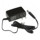
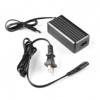
You will also need a 5V power supply to run your controller and new lights. Each APA102C can draw as much as 60mA when red, green and blue are all full-on, so you'll want to have something a little beefy. For testing purposes (assuming that you do not turn all the LEDs fully on), you can use a computer's USB port and cable. A wall adapter capable of 2.5A should be plenty for our demonstration if you are placing it in an installation. If you've got a bigger project in mind, check out the Mean Well 5V/20A supply.
Power Supply - 12V/5V (2A)
TOL-15664Wires
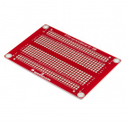
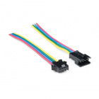
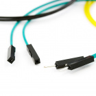
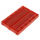
You'll also need some way to connect the boards and an Arduino. If you are using a breakout board or pieces of the LED strip, you could use a combination of jumper wires (such as M/M or M/F) and breadboard (solderless or solderable). Or you could just go with a few pieces of hookup wire or 4-pin JST-SM pigtail connectors.
Tools
Lastly, you are going to need a few tools. A soldering iron, some solder, general soldering accessories, wire, and a wire stripper should do if you are modifying the LED strip or connecting to a breakout board.
Suggested Reading
We're tried to make this hookup guide as simple as possible, but you may be lacking some basic information that could help your understanding as we go forward. For more info, check out these tutorials.
How to Solder: Through-Hole Soldering
Installing an Arduino Library
Binary
How to Power a Project
Logic Levels
APA102 Hardware Overview
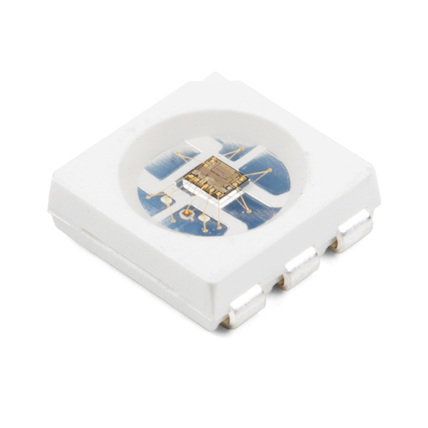
The APA102-based LED is much more than meets the eye. It may look like a common 5050-sized (5x5mm) LED, but there's actually an integrated circuit embedded inside there too. If you look really hard, you can see the tiny black chip hidden in there, along with minuscule gold wires connecting the chip to the LED. Below is a close up of an APA102.
Data Transmission Interface
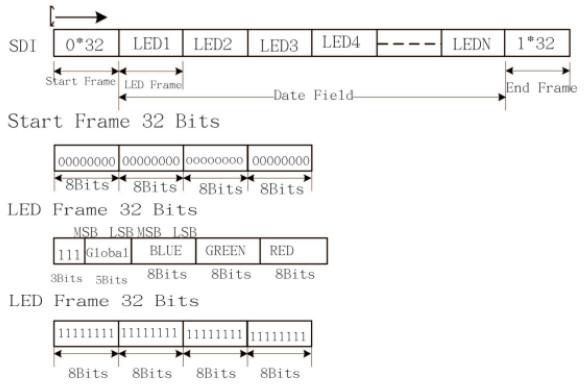
The communication interface between a microcontroller and the APA102 is not as strict WS2812's timing since it uses a 2-wire communication protocol, which consists of a clock and data line. Basically a simplified SPI interface without a slave pin.
The data frame consists of a start frame, data field for the LEDs, and an end frame. The data field consists of a frame for each LED attached to the strand. Each LED frame starts with three 1's , 5 bits for brightness, 8 bits for blue, 8 bits for green, and 8 bits for red. The larger the value of a specific color is, the brighter it will be. If every color is set to 0, the LED will be off. If every color is set to max -- 255 -- the LED will be as bright and white as can be.
With the added clock line, you can use it with both a real-time processor (i.e. an Arduino) and microprocessor (i.e. Raspberry Pi). You will just need to ensure that you are using a logic level converter for 3.3V systems and make sure there is APA102 support for your architecture.
LuMini
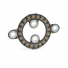
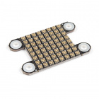
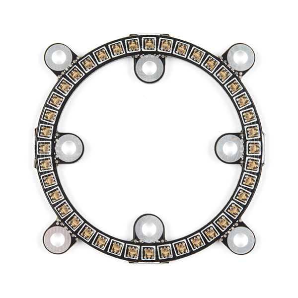
The LuMini is a miniaturized version of the Lumenati LEDs. The LuMini uses the APA102-2020 size for tight pixel densities. While they have a higher resolution, the tradeoff is there is a limitation in how bright they can be turned on. Having a high brightness can result in damage to the LED and PCB due the ability to dissipate heat with the small package.
 |
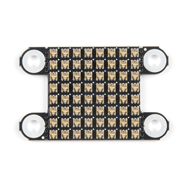 |
| LuMini Ring - 2 Inch Version | LuMini Matrix |
For more information, check out the following tutorials to get started.
LuMini Ring Hookup Guide
LuMini 8x8 Matrix Hookup Guide
Addressable LED Strips
If you need an abundance of WS2812 LEDs in a slick, pre-assembled form factor these addressable LED strips might be for you.
The APA102 addressable LED strips come in a few flavors, which vary by size and sealant. You can get them in either 1m or 5m lengths, or high density. For each length the strip, they can be either covered by a waterproof sealant or left bare.
Connecting to the Strips
Each end of the LED strip is terminated with a set of four colored wires: red, blue, green, and yellow. Two wires are for power, one wire for clock, and another wire transmits data either into or out of the strip:
| Red | Vcc | APA102 power supply. Should be a regulated supply between 5V and 5.5V. |
|---|---|---|
| Blue | Clock | Clock |
| Green | Data In/Out | Serial data in/out. Look at arrows and labels on strip to check which it is. |
| Yellow | GND | Ground. 0V. |
Each of the wire pigtails are terminated by a four-pin JST SM connector, which you can use to connect string strips together. Typically, the addressable LEDs use a polarized JST SM connector with the male housing receptacle with (female pin sockets) connected to the DI side as shown with the connector on the left side of the image. The female housing receptacle (with male pins) coming connected to the DO side as shown with the connector on the right side of the image.
For the first strip in a string, you can either connect to a mating connector, or cut and strip the wires, and connect them to your controlling device. To reuse the rest of the LED strip, check out the LED strip pigtail connector to easily connect the cut strips:
Hardware Hookup
The great thing about these LEDs is they're super easy to chain together. Plus just two pins from your microcontroller is required to control an entire strip of LEDs. In this example, we'll control one 1M LED strip, but you should be safe to increase that ten-fold or even more.
Solder/Wire Something
The first assembly step for each of these products is creating a reliable, electrical connection from the LED to your control board. For a secure connection, you'll need to solder pigtail wires to a protoboard/shield to connect if you decide to place them into a project with a lot of movement or strip if you cut them into strands. You can also strip and splice some hookup wire to connect the LED strips.
How to Solder: Through-Hole Soldering
Working with Wire
Connecting to an Arduino
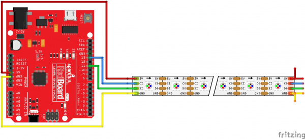
This hookup is fairly straightforward. You can power the breakout board(s) with USB power and the Arduino's 5V and GND pins. Then all you need is to send data and clock signal to the LED. Let's go with pin 11 and 13, respectively. We recommend using a hardware pins for your microcontroller for best performance. Simply connect four M/F jumper wires to the RedBoard Qwiic.
Protect Your APA102's!
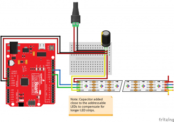
In addition to the hookup above, we recommend adding a capacitor as close as possible to your addressable LEDs like the WS2812's to help you get the most out of your APA102-based devices for long strips. Below is an example with an addressable LED strip and separate power supply via the barrel jack connector. Read below for more information on suggested values!
Add a Big Smoothing Capacitor
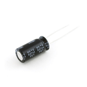
Before connecting the APA102 to a power source, connect a big capacitor from power to ground. A cap between 100µF and 1000µF should be good.
This cap will help to smooth out your power supply. The current draw of a APA102 can vary wildly, and as current draw grows and shrinks it'll be up to your power source to compensate. The cap will act as a "power reservoir" to store energy in case the supply dips.
Try to place this cap as close to your APA102 as possible by placing it in parallel to the Vcc and GND pins.
Keep Wires Short!
Wires don't conduct perfectly. They'll inevitably induce some voltage loss, especially when they're really long. Try to keep wires between your power supply, Arduino, and APA102 as short as possible to minimize this loss.
Arduino Library Overview
Note: This example assumes you are using the latest version of the Arduino IDE on your desktop. If this is your first time using Arduino, please review our tutorial on installing the Arduino IDE. If you have not previously installed an Arduino library, please check out our installation guide.
For the scope of this tutorial, we'll be using the FastLED library. The library will help you control the APA102's and provides example code to get the most our of your project. You can obtain these libraries through the Arduino Library Manager by searching for FastLED. The library also supports other LED chipsets. The second option is to download the ZIP file below from its GitHub repository to manually install it.
Parameters
When using the FastLED library, certain parameters need to be adjusted at a minimum to be compatible with the chipset. Depending on the example, the DATA_PIN can be referred to as LED_PIN. You may need to define the CLOCK_PIN or it can also be referred to as CLK_PIN. We recommend using a dedicated hardware SPI for best performance. However, if you decide to use a different pin, the library can be reconfigured to bit bang the pins. The LED_TYPE would be defined as the APA102 chipset. There are 60 LEDs per LED strip so NUM_LEDs needs to be set to 60. The COLOR_ORDER is BGR.
Once these parameters are set, you will need to initialize the LED strip configuration using .addLEDs<>() in the setup() function. Depending on the brightness and complexity of the animation, there are several methods to adjust the quality and appearance of the project like the color temperature, dither mode, refresh rate, FPS, or color correction. Below are two methods of setting up the LED strip for the APA102 configuration that we'll be using in this tutorial.
language:c
FastLED.addLeds<APA102, DATA_PIN, CLOCK_PIN, BGR>(leds, NUM_LEDS);
FastLED.addLeds<LED_TYPE,DATA_PIN,CLK_PIN,COLOR_ORDER>(leds, NUM_LEDS).setCorrection(TypicalLEDStrip);
FastLED.setBrightness() function to 32 in the setup() to avoid damaging the LEDs.
Microcontroller
The library is supported on a variety of Arduino compatible platforms. For a list of supported AVR or ARM microcontrollers, check out the list on the library's README.md.
Arduino Example
The FastLED library includes a few examples for a variety of addressable LED chipsets to get started. The following examples will demonstrate how to modify the example to use with the APA102 chipset. For more information, check out the FastLED Library's wiki.
FastLED Blink Modification
For simplicity, let's blink one LED from the APA102 LED strip using the FastLED's Blink.ino example by following the steps listed below. After installing the library, head to File > Examples > FastLED > Blink to open the example in Arduino.
- First, adjust the number of LEDs (
NUM_LEDs) in the strip to60. - Change the
DATA_PINto pin11. - Change
CLOCK_PINto13. - In the
setup(),- Comment out a line by adding
//in front ofFastLED.addLeds<NEOPIXEL, DATA_PIN>(leds, NUM_LEDS);. - Uncomment out the LED arrangement for the
APA102chipset by removing the//beforeFastLED.addLeds<APA102, DATA_PIN, CLOCK_PIN, RGB>(leds, NUM_LEDS);.
- Comment out a line by adding
- Modify the color order by changing
RGBtoBGR.
Once the code is adjusted, select your board and COM port. Then upload the code to blink the first LED of the strand! After uploading, you should see the first LED blink with red.
Now that you have the LED blinking red, try copying and pasting the code in the loop() function two more times to see if you can blink a green and blue. This is useful to test if your APA102 is outputting the correct color before mixing the colors.
Or copy and paste the modified example in an Arduino sketch. Select the COM port and board, and hit the upload button.
language:c
#include <FastLED.h>

// How many leds in your strip?
#define NUM_LEDS 60

// For led chips like Neopixels, which have a data line, ground, and power, you just
// need to define DATA_PIN.  For led chipsets that are SPI based (four wires - data, clock,
// ground, and power), like the LPD8806 define both DATA_PIN and CLOCK_PIN
#define DATA_PIN 11
#define CLOCK_PIN 13

// Define the array of leds
CRGB leds[NUM_LEDS];

void setup() {
  // Uncomment/edit one of the following lines for your leds arrangement.
  // FastLED.addLeds<TM1803, DATA_PIN, RGB>(leds, NUM_LEDS);
  // FastLED.addLeds<TM1804, DATA_PIN, RGB>(leds, NUM_LEDS);
  // FastLED.addLeds<TM1809, DATA_PIN, RGB>(leds, NUM_LEDS);
  // FastLED.addLeds<WS2811, DATA_PIN, RGB>(leds, NUM_LEDS);
  // FastLED.addLeds<WS2812, DATA_PIN, RGB>(leds, NUM_LEDS);
  // FastLED.addLeds<WS2812B, DATA_PIN, RGB>(leds, NUM_LEDS);
  // FastLED.addLeds<NEOPIXEL, DATA_PIN>(leds, NUM_LEDS);
  // FastLED.addLeds<APA104, DATA_PIN, RGB>(leds, NUM_LEDS);
  // FastLED.addLeds<UCS1903, DATA_PIN, RGB>(leds, NUM_LEDS);
  // FastLED.addLeds<UCS1903B, DATA_PIN, RGB>(leds, NUM_LEDS);
  // FastLED.addLeds<GW6205, DATA_PIN, RGB>(leds, NUM_LEDS);
  // FastLED.addLeds<GW6205_400, DATA_PIN, RGB>(leds, NUM_LEDS);

  // FastLED.addLeds<WS2801, RGB>(leds, NUM_LEDS);
  // FastLED.addLeds<SM16716, RGB>(leds, NUM_LEDS);
  // FastLED.addLeds<LPD8806, RGB>(leds, NUM_LEDS);
  // FastLED.addLeds<P9813, RGB>(leds, NUM_LEDS);
  // FastLED.addLeds<APA102, RGB>(leds, NUM_LEDS);
  // FastLED.addLeds<DOTSTAR, RGB>(leds, NUM_LEDS);

  // FastLED.addLeds<WS2801, DATA_PIN, CLOCK_PIN, RGB>(leds, NUM_LEDS);
  // FastLED.addLeds<SM16716, DATA_PIN, CLOCK_PIN, RGB>(leds, NUM_LEDS);
  // FastLED.addLeds<LPD8806, DATA_PIN, CLOCK_PIN, RGB>(leds, NUM_LEDS);
  // FastLED.addLeds<P9813, DATA_PIN, CLOCK_PIN, RGB>(leds, NUM_LEDS);
  FastLED.addLeds<APA102, DATA_PIN, CLOCK_PIN, BGR>(leds, NUM_LEDS);
  // FastLED.addLeds<DOTSTAR, DATA_PIN, CLOCK_PIN, RGB>(leds, NUM_LEDS);
}

void loop() {
  // Turn the LED on, then pause
  leds[0] = CRGB::Red;
  FastLED.show();
  delay(500);
  // Now turn the LED off, then pause
  leds[0] = CRGB::Black;
  FastLED.show();
  delay(500);

  // Turn the LED on, then pause
  leds[0] = CRGB::Green;
  FastLED.show();
  delay(500);
  // Now turn the LED off, then pause
  leds[0] = CRGB::Black;
  FastLED.show();
  delay(500);

  // Turn the LED on, then pause
  leds[0] = CRGB::Blue;
  FastLED.show();
  delay(500);
  // Now turn the LED off, then pause
  leds[0] = CRGB::Black;
  FastLED.show();
  delay(500);
}
There's a variety of pre-defined colors in the FastLED library that you can use. Try looking at the keywords.txt to try out the different colors. Then try adjusting the array number to turn on different LEDs on the strip.
Color Palette Modification
There are a few demos with different animations in the library. Let's try looking at the color palette demo. The color palette cycles the LED strip with few different palettes. The first is a rainbow, rainbow stripes, purple and green stripes, random, white stripes, cloud-like colors, and red/white/blue stripes. There is an option to blend the LED animation for the palettes depending on your preference and project. Head to File > Examples > FastLED > ColorPalette to open the example in Arduino.
- First, comment out a line by adding
//in front of#define LED_PIN 5. - We'll define that pin by adding the following line
#define DATA_PIN 11. - We'll add an additional pin for the clock by adding the following line
#define CLK_PIN 13. - Adjust the number of LEDs (
NUM_LEDS) to60. - Change the
LED_TYPEto pinAPA102. - Modify the color order by changing
GRBtoBGR. - In the
setup(),- Comment out a line by adding
//in front ofFastLED.addLeds<LED_TYPE, LED_PIN, COLOR_ORDER>(leds, NUM_LEDS).setCorrection( TypicalLEDStrip );. - Add the LED arrangement for the
APA102chipset by adding the following lineFastLED.addLeds<LED_TYPE,DATA_PIN,CLK_PIN,COLOR_ORDER>(leds, NUM_LEDS).setCorrection(TypicalLEDStrip);.
- Comment out a line by adding
Or copy and paste the modified example in an Arduino sketch. Or copy and paste the modified example in an Arduino sketch. Select the COM port and board, and hit the upload button.
language:c
   #include <FastLED.h>

//#define LED_PIN     5 // redefined in the next line
#define DATA_PIN     11
#define CLK_PIN     13
#define NUM_LEDS    60
#define BRIGHTNESS  64
#define LED_TYPE    APA102
#define COLOR_ORDER BGR
CRGB leds[NUM_LEDS];

#define UPDATES_PER_SECOND 100

// This example shows several ways to set up and use 'palettes' of colors
// with FastLED.
//
// These compact palettes provide an easy way to re-colorize your
// animation on the fly, quickly, easily, and with low overhead.
//
// USING palettes is MUCH simpler in practice than in theory, so first just
// run this sketch, and watch the pretty lights as you then read through
// the code.  Although this sketch has eight (or more) different color schemes,
// the entire sketch compiles down to about 6.5K on AVR.
//
// FastLED provides a few pre-configured color palettes, and makes it
// extremely easy to make up your own color schemes with palettes.
//
// Some notes on the more abstract 'theory and practice' of
// FastLED compact palettes are at the bottom of this file.


CRGBPalette16 currentPalette;
TBlendType    currentBlending;

extern CRGBPalette16 myRedWhiteBluePalette;
extern const TProgmemPalette16 myRedWhiteBluePalette_p PROGMEM;


void setup() {
    delay( 3000 ); // power-up safety delay
    //FastLED.addLeds<LED_TYPE, LED_PIN, COLOR_ORDER>(leds, NUM_LEDS).setCorrection( TypicalLEDStrip );
    FastLED.addLeds<LED_TYPE,DATA_PIN,CLK_PIN,COLOR_ORDER>(leds, NUM_LEDS).setCorrection(TypicalLEDStrip);
    FastLED.setBrightness(  BRIGHTNESS );

    currentPalette = RainbowColors_p;
    currentBlending = LINEARBLEND;
}


void loop()
{
    ChangePalettePeriodically();

    static uint8_t startIndex = 0;
    startIndex = startIndex + 1; /* motion speed */

    FillLEDsFromPaletteColors( startIndex);

    FastLED.show();
    FastLED.delay(1000 / UPDATES_PER_SECOND);
}

void FillLEDsFromPaletteColors( uint8_t colorIndex)
{
    uint8_t brightness = 255;

    for( int i = 0; i < NUM_LEDS; i++) {
        leds[i] = ColorFromPalette( currentPalette, colorIndex, brightness, currentBlending);
        colorIndex += 3;
    }
}


// There are several different palettes of colors demonstrated here.
//
// FastLED provides several 'preset' palettes: RainbowColors_p, RainbowStripeColors_p,
// OceanColors_p, CloudColors_p, LavaColors_p, ForestColors_p, and PartyColors_p.
//
// Additionally, you can manually define your own color palettes, or you can write
// code that creates color palettes on the fly.  All are shown here.

void ChangePalettePeriodically()
{
    uint8_t secondHand = (millis() / 1000) % 60;
    static uint8_t lastSecond = 99;

    if( lastSecond != secondHand) {
        lastSecond = secondHand;
        if( secondHand ==  0)  { currentPalette = RainbowColors_p;         currentBlending = LINEARBLEND; }
        if( secondHand == 10)  { currentPalette = RainbowStripeColors_p;   currentBlending = NOBLEND;  }
        if( secondHand == 15)  { currentPalette = RainbowStripeColors_p;   currentBlending = LINEARBLEND; }
        if( secondHand == 20)  { SetupPurpleAndGreenPalette();             currentBlending = LINEARBLEND; }
        if( secondHand == 25)  { SetupTotallyRandomPalette();              currentBlending = LINEARBLEND; }
        if( secondHand == 30)  { SetupBlackAndWhiteStripedPalette();       currentBlending = NOBLEND; }
        if( secondHand == 35)  { SetupBlackAndWhiteStripedPalette();       currentBlending = LINEARBLEND; }
        if( secondHand == 40)  { currentPalette = CloudColors_p;           currentBlending = LINEARBLEND; }
        if( secondHand == 45)  { currentPalette = PartyColors_p;           currentBlending = LINEARBLEND; }
        if( secondHand == 50)  { currentPalette = myRedWhiteBluePalette_p; currentBlending = NOBLEND;  }
        if( secondHand == 55)  { currentPalette = myRedWhiteBluePalette_p; currentBlending = LINEARBLEND; }
    }
}

// This function fills the palette with totally random colors.
void SetupTotallyRandomPalette()
{
    for( int i = 0; i < 16; i++) {
        currentPalette[i] = CHSV( random8(), 255, random8());
    }
}

// This function sets up a palette of black and white stripes,
// using code.  Since the palette is effectively an array of
// sixteen CRGB colors, the various fill_* functions can be used
// to set them up.
void SetupBlackAndWhiteStripedPalette()
{
    // 'black out' all 16 palette entries...
    fill_solid( currentPalette, 16, CRGB::Black);
    // and set every fourth one to white.
    currentPalette[0] = CRGB::White;
    currentPalette[4] = CRGB::White;
    currentPalette[8] = CRGB::White;
    currentPalette[12] = CRGB::White;

}

// This function sets up a palette of purple and green stripes.
void SetupPurpleAndGreenPalette()
{
    CRGB purple = CHSV( HUE_PURPLE, 255, 255);
    CRGB green  = CHSV( HUE_GREEN, 255, 255);
    CRGB black  = CRGB::Black;

    currentPalette = CRGBPalette16(
                                   green,  green,  black,  black,
                                   purple, purple, black,  black,
                                   green,  green,  black,  black,
                                   purple, purple, black,  black );
}


// This example shows how to set up a static color palette
// which is stored in PROGMEM (flash), which is almost always more
// plentiful than RAM.  A static PROGMEM palette like this
// takes up 64 bytes of flash.
const TProgmemPalette16 myRedWhiteBluePalette_p PROGMEM =
{
    CRGB::Red,
    CRGB::Gray, // 'white' is too bright compared to red and blue
    CRGB::Blue,
    CRGB::Black,

    CRGB::Red,
    CRGB::Gray,
    CRGB::Blue,
    CRGB::Black,

    CRGB::Red,
    CRGB::Red,
    CRGB::Gray,
    CRGB::Gray,
    CRGB::Blue,
    CRGB::Blue,
    CRGB::Black,
    CRGB::Black
};


// Additional notes on FastLED compact palettes:
//
// Normally, in computer graphics, the palette (or "color lookup table")
// has 256 entries, each containing a specific 24-bit RGB color.  You can then
// index into the color palette using a simple 8-bit (one byte) value.
// A 256-entry color palette takes up 768 bytes of RAM, which on Arduino
// is quite possibly "too many" bytes.
//
// FastLED does offer traditional 256-element palettes, for setups that
// can afford the 768-byte cost in RAM.
//
// However, FastLED also offers a compact alternative.  FastLED offers
// palettes that store 16 distinct entries, but can be accessed AS IF
// they actually have 256 entries; this is accomplished by interpolating
// between the 16 explicit entries to create fifteen intermediate palette
// entries between each pair.
//
// So for example, if you set the first two explicit entries of a compact
// palette to Green (0,255,0) and Blue (0,0,255), and then retrieved
// the first sixteen entries from the virtual palette (of 256), you'd get
// Green, followed by a smooth gradient from green-to-blue, and then Blue.
You should see the sequence of colors animating along the strip. There's a few more "preset" palettes defined in the library that you can use. Try looking at the colorpalettes.cpp for more and replacing ChangePalettePeriodically()'s currentPalette value to the preset of your choice. You can also manually define your own palette of your choice depending on your project based on the pre-define colors in the keywords.txt similar to the ones defined after the loop() function.
Demo Reel Modification
Another example that we will look at is the Demo Reel. Head to File > Examples > FastLED > DemoReel100 to open the example in Arduino.
- First, adjust the
DATA_PINto pin11. - Uncomment the
CLK_PINby removing the//and defining it as pin13. - Change the
LED_TYPEto pinAPA102. - Modify the color order (
COLOR_ORDER) by changingGRBtoBGR. - Adjust the number of LEDs (
NUM_LEDS) to 60. - In the
setup(),- Comment out a line by adding
//in front ofFastLED.addLeds<LED_TYPE,DATA_PIN,COLOR_ORDER>(leds, NUM_LEDS).setCorrection(TypicalLEDStrip);. - Add the LED arrangement for the
APA102chipset by removing the//in front ofFastLED.addLeds<LED_TYPE,DATA_PIN,CLK_PIN,COLOR_ORDER>(leds, NUM_LEDS).setCorrection(TypicalLEDStrip);.
- Comment out a line by adding
Or copy and paste the modified example in an Arduino sketch. Select the COM port and board, and hit the upload button.
language:c
#include <FastLED.h>

FASTLED_USING_NAMESPACE

// FastLED "100-lines-of-code" demo reel, showing just a few
// of the kinds of animation patterns you can quickly and easily
// compose using FastLED.
//
// This example also shows one easy way to define multiple
// animations patterns and have them automatically rotate.
//
// -Mark Kriegsman, December 2014

#if defined(FASTLED_VERSION) && (FASTLED_VERSION < 3001000)
#warning "Requires FastLED 3.1 or later; check github for latest code."
#endif

#define DATA_PIN    11
#define CLK_PIN     13
#define LED_TYPE    APA102
#define COLOR_ORDER BGR
#define NUM_LEDS    60
CRGB leds[NUM_LEDS];

#define BRIGHTNESS          96
#define FRAMES_PER_SECOND  120

void setup() {
  delay(3000); // 3 second delay for recovery

  // tell FastLED about the LED strip configuration
  //FastLED.addLeds<LED_TYPE,DATA_PIN,COLOR_ORDER>(leds, NUM_LEDS).setCorrection(TypicalLEDStrip);
  FastLED.addLeds<LED_TYPE,DATA_PIN,CLK_PIN,COLOR_ORDER>(leds, NUM_LEDS).setCorrection(TypicalLEDStrip);

  // set master brightness control
  FastLED.setBrightness(BRIGHTNESS);
}


// List of patterns to cycle through.  Each is defined as a separate function below.
typedef void (*SimplePatternList[])();
SimplePatternList gPatterns = { rainbow, rainbowWithGlitter, confetti, sinelon, juggle, bpm };

uint8_t gCurrentPatternNumber = 0; // Index number of which pattern is current
uint8_t gHue = 0; // rotating "base color" used by many of the patterns

void loop()
{
  // Call the current pattern function once, updating the 'leds' array
  gPatterns[gCurrentPatternNumber]();

  // send the 'leds' array out to the actual LED strip
  FastLED.show();
  // insert a delay to keep the framerate modest
  FastLED.delay(1000/FRAMES_PER_SECOND);

  // do some periodic updates
  EVERY_N_MILLISECONDS( 20 ) { gHue++; } // slowly cycle the "base color" through the rainbow
  EVERY_N_SECONDS( 10 ) { nextPattern(); } // change patterns periodically
}

#define ARRAY_SIZE(A) (sizeof(A) / sizeof((A)[0]))

void nextPattern()
{
  // add one to the current pattern number, and wrap around at the end
  gCurrentPatternNumber = (gCurrentPatternNumber + 1) % ARRAY_SIZE( gPatterns);
}

void rainbow()
{
  // FastLED's built-in rainbow generator
  fill_rainbow( leds, NUM_LEDS, gHue, 7);
}

void rainbowWithGlitter()
{
  // built-in FastLED rainbow, plus some random sparkly glitter
  rainbow();
  addGlitter(80);
}

void addGlitter( fract8 chanceOfGlitter)
{
  if( random8() < chanceOfGlitter) {
    leds[ random16(NUM_LEDS) ] += CRGB::White;
  }
}

void confetti()
{
  // random colored speckles that blink in and fade smoothly
  fadeToBlackBy( leds, NUM_LEDS, 10);
  int pos = random16(NUM_LEDS);
  leds[pos] += CHSV( gHue + random8(64), 200, 255);
}

void sinelon()
{
  // a colored dot sweeping back and forth, with fading trails
  fadeToBlackBy( leds, NUM_LEDS, 20);
  int pos = beatsin16( 13, 0, NUM_LEDS-1 );
  leds[pos] += CHSV( gHue, 255, 192);
}

void bpm()
{
  // colored stripes pulsing at a defined Beats-Per-Minute (BPM)
  uint8_t BeatsPerMinute = 62;
  CRGBPalette16 palette = PartyColors_p;
  uint8_t beat = beatsin8( BeatsPerMinute, 64, 255);
  for( int i = 0; i < NUM_LEDS; i++) { //9948
    leds[i] = ColorFromPalette(palette, gHue+(i*2), beat-gHue+(i*10));
  }
}

void juggle() {
  // eight colored dots, weaving in and out of sync with each other
  fadeToBlackBy( leds, NUM_LEDS, 20);
  byte dothue = 0;
  for( int i = 0; i < 8; i++) {
    leds[beatsin16( i+7, 0, NUM_LEDS-1 )] |= CHSV(dothue, 200, 255);
    dothue += 32;
  }
}
The LEDs will begin animating based on the functions defined in the demo. Read through the example code to see how they were written or bask in the glow of the animations running along the strip.
More Examples!
Now that we have some experience using three examples, try modifying and testing out the other code included the FastLED library!
Or you can check out the Lumenati, LuMini ring, and LuMini matrix guides that use the FastLED library.
Lumenati Hookup Guide
LuMini Ring Hookup Guide
LuMini 8x8 Matrix Hookup Guide
FastLED Documentation and FAQ
The FastLED is a pretty big and complex library. There are quite a lot of features. Besides looking through the code's comments, check out some of FastLED's documentation and FAQ for more information.
Python Examples
If you are looking to control the LEDs in a different language, try checking out the following tutorials to control the APA's with Python. You can control them via a microcontroller using the LumiDrive or a single board computer using the Raspberry Pi. Check out the following tutorials for more information.
LumiDrive Hookup Guide
Resources and Going Further
Accessories
Try writing some additional code and adding more features in order to change the brightness or mode with the APA102 using a potentiometer or button. Or try adding a sensor to trigger animations based on sound to react to the beat of a track!
Depending on the design, there are some shields for the Teensy that breakout pins for the APA102. Just make sure to check the wiring to ensure that it matches the connection for the LED strips.
Teensy Prop Shield LC
DEV-13996For more information about the APA102, check out the resources below:
Now that you've got the gist of the APA102's, how are you going to use it in a project? Need some inspiration? Check out these tutorials for ideas to diffuse or daisy chain longer strips:
Building Large LED Installations
LED Cloud-Connected Cloud
Mean Well LED Switching Power Supply Hookup Guide
SparkFun ESP32 DMX to LED Shield
Or check out some of these blog posts for ideas:

