Activity Guide for SparkFun Tinker Kit
This Tutorial is Retired!
This tutorial covers concepts or technologies that are no longer current. It's still here for you to read and enjoy, but may not be as useful as our newest tutorials.
View the updated tutorial: Tinker Kit Circuit Guide
 Joel_E_B,
  bboyho
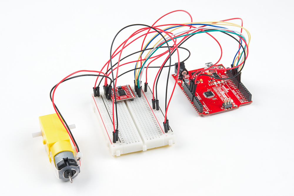
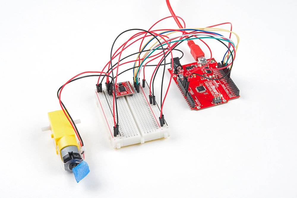
 Circuit 10: Motor Basics
In this circuit you will learn the basic concepts behind motor control. Motors require a lot of current, so you can’t drive them directly from a digital pin on the RedBoard. Instead, you’ll use what is known as a motor controller or motor driver board to power and spin the motor accordingly.
Parts Needed
You will need the following parts:
- 1x Breadboard
- 1x SparkFun RedBoard
- 16x Jumper Wires
- 1x TB6612FNG Motor Driver (w/ Headers)
- 1x Hobby Gearmotor
Didn't Get the Tinker Kit?
If you are conducting this experiment and didn't get the Tinker Kit, we suggest using these parts:


New Components
DC Gearmotors
The motors in your Tinker Kit have two main parts: a small DC motor that spins quickly and a plastic gearbox that gears down that output from the hobby motor so that it is slower but stronger, allowing it to move your robot. The motors have a clever design so that you can attach things that you want to spin fast (like a small fan or flag) to the hobby motor, and things that you want to be strong (like a wheel) to the plastic axle sticking out the side of the motor.
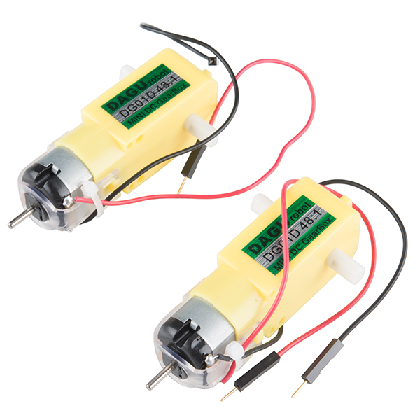
Inside the hobby motor are coils of wire that generate magnetic fields when electricity flows through them. When power is supplied to these electromagnets, they spin the drive shaft of the motor.
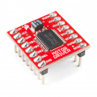
TB6612FNG Motor Driver
If you switch the direction of current through a motor by swapping the positive and negative leads, the motor will spin in the opposite direction. Motor controllers contain a set of switches (called an H-bridge) that let you easily control the direction of one or more motors. The TB6612FNG Motor Driver takes commands for each motor over three wires (two wires control direction, and one controls speed), then uses these signals to control the current through two wires attached to your motor.

New Concepts
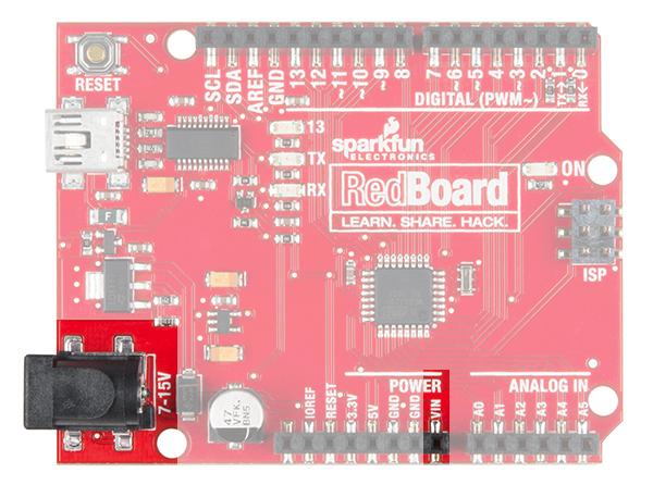
Voltage In (VIN)
This circuit utilizes the VIN pin found with the other power pins. The VIN pin outputs a voltage that varies based on whatever voltage the RedBoard is powered with. If the RedBoard is powered through the USB port, then the voltage on VIN will be about 4.6--5V. However, if you power the RedBoard through the barrel jack (highlighted in the picture below), the VIN pin will reflect that voltage. For example, if you were to power the barrel jack with 9V, the voltage out on VIN would also be 9V.
Integrated Circuits (ICs) and Breakout Boards
An Integrated Circuit (IC) is a collection of electronic components --- resistors, transistors, capacitors, etc. --- all stuffed into a tiny chip and connected together to achieve a common goal. They come in all sorts of flavors, shapes and sizes. The chip that powers the RedBoard, the ATMega328, is an IC. The chip on the motor driver, the TB6612FNG, is another IC, one designed to control motors, referred to as an H-bridge.
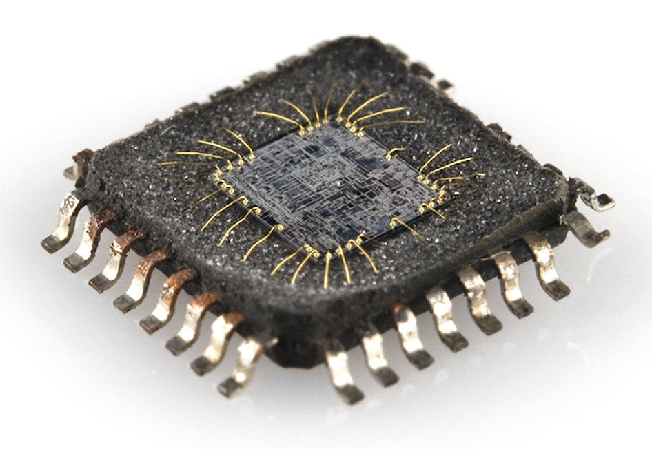
Integrated circuits are often too small to work with by hand. To make working with ICs easier and to make them breadboard-compatible, they are often added to a breakout board, which is a printed circuit board that connects all the IC's tiny legs to larger ones that fit in a breadboard. The motor driver board in your kit is an example of a breakout board.
Hardware Hookup
| Polarized Components | Pay special attention to the component’s markings indicating how to place it on the breadboard. Polarized components can only be connected to a circuit in one direction. |
Most ICs have polarity and usually have a polarity marking in one of the corners. The motor driver is no exception. Be sure to insert the motor driver as indicated in the circuit diagrams. The motor driver pins are shown in the image below.
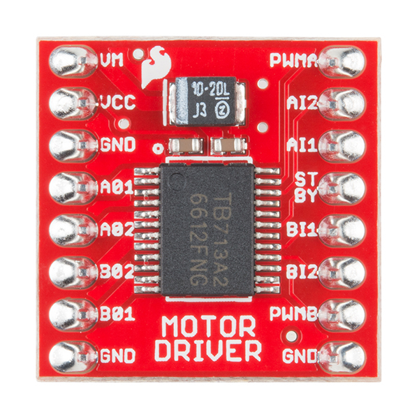
Each pin and its function is covered in the table below.
| Pin Label | Function | Power/Input/Output | Notes |
|---|---|---|---|
| VM | Motor Voltage | Power | This is where you provide power for the motors (2.2V to 13.5V) |
| VCC | Logic Voltage | Power | This is the voltage to power the chip and talk to the microcontroller (2.7V to 5.5V) |
| GND | Ground | Power | Common Ground for both motor voltage and logic voltage (all GND pins are connected) |
| STBY | Standby | Input | Allows the H-bridges to work when high (has a pulldown resistor so it must actively be pulled high) |
| AIN1/BIN1 | Input 1 for channels A/B | Input | One of the two inputs that determines the direction |
| AIN2/BIN2 | Input 2 for channels A/B | Input | One of the two inputs that determines the direction |
| PWMA/PWMB | PWM input for channels A/B | Input | PWM input that controls the speed |
| A01/B01 | Output 1 for channels A/B | Output | One of the two outputs to connect the motor |
| A02/B02 | Output 2 for channels A/B | Output | One of the two outputs to connect the motor |
When you're finished with the circuit, removing the motor driver from the breadboard can be difficult due to its numerous legs. To make this easier, use the a screwdriver as a lever to gently pry it out. Be careful not to bend the legs as you remove it by slowly lifting the motor driver off the breadboard from each side.

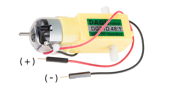
The motors are also polarized. However, motors are unique in that they will still work when the two connections are reversed. They will just spin in the opposite direction when hooked up backward. To keep things simple, always think of the red wire as positive ( + ) and the black wire as negative ( - ).
Last, the switch is not polarized. It works the same no matter its orientation.
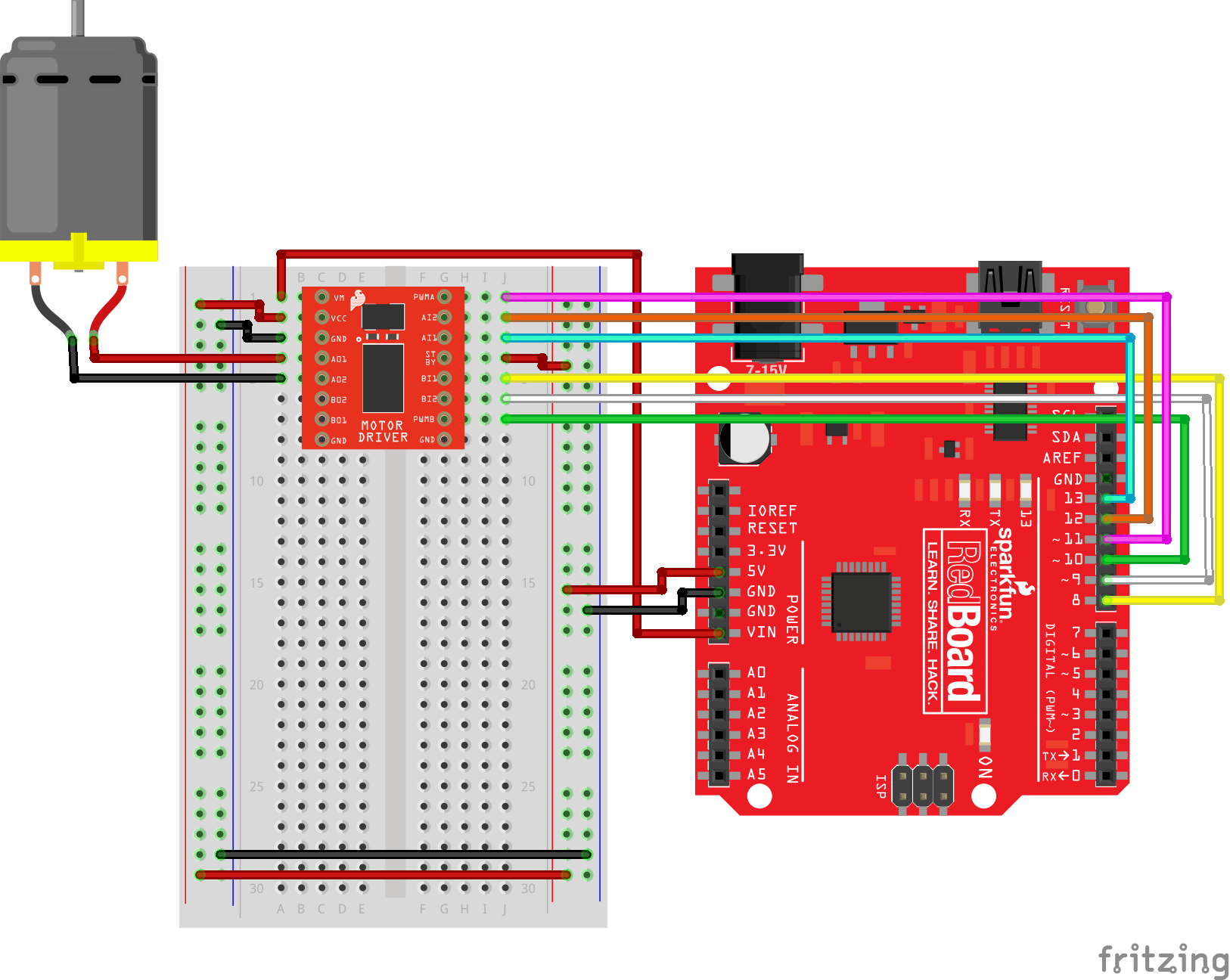
Ready to start hooking everything up? Check out the circuit diagram and hookup table below to see how everything is connected.
Circuit Diagram
Hookup Table
| Component | RedBoard | Breadboard | Breadboard | Breadboard |
|---|---|---|---|---|
| Jumper Wire | 5V | 5V Rail ( + ) | ||
| Jumper Wire | GND | GND Rail ( - ) | ||
| Jumper Wire | 5V Rail ( + ) | 5V Rail ( + ) | ||
| Jumper Wire | GND Rail ( - ) | GND Rail ( - ) | ||
| Jumper Wire | VIN | A1 | ||
| Motor Driver | C1-C8 (VM on C1) | G1-G8 (PWMA on G1) | ||
| Jumper Wire | A2 | 5V Rail ( + ) | ||
| Jumper Wire | A3 | GND Rail ( - ) | ||
| Jumper Wire | Digital Pin 8 | J5 | ||
| Jumper Wire | Digital Pin 9 | J6 | ||
| Jumper Wire | Digital Pin 10 | J7 | ||
| Jumper Wire | J4 | 5V Rail ( + ) | ||
| Jumper Wire | Digital Pin 11 | J1 | ||
| Jumper Wire | Digital Pin 12 | J2 | ||
| Jumper Wire | Digital Pin 13 | J3 | ||
| Motor | A4 (Red +) | A5 (Black -) |
Open the Sketch
Copy and paste the following code into the Arduino IDE. Hit upload, and see what happens!
language:cpp
/*
SparkFun Tinker Kit
Circuit 10: Motor Basics

Learn how to control one motor with the motor driver.

This sketch was written by SparkFun Electronics, with lots of help from the Arduino community.
This code is completely free for any use.

View circuit diagram and instructions at: https://learn.sparkfun.com/tutorials/activity-guide-for-sparkfun-tinker-kit/circuit-10-motor-basics
Download drawings and code at: https://github.com/sparkfun/SparkFun_Tinker_Kit_Code/
*/

//PIN VARIABLES
//the motor will be controlled by the motor A pins on the motor driver
const int AIN1 = 13;           //control pin 1 on the motor driver for the right motor
const int AIN2 = 12;            //control pin 2 on the motor driver for the right motor
const int PWMA = 11;            //speed control pin on the motor driver for the right motor

//VARIABLES
int motorSpeed = 0;       //starting speed for the motor

void setup() {
  //set the motor contro pins as outputs
  pinMode(AIN1, OUTPUT);
  pinMode(AIN2, OUTPUT);
  pinMode(PWMA, OUTPUT);
}

void loop() {
    //drive motor forward (positive speed)
    digitalWrite(AIN1, HIGH);                         //set pin 1 to high
    digitalWrite(AIN2, LOW);                          //set pin 2 to low
    analogWrite(PWMA, 255);               //now that the motor direction is set, drive it at max speed
    delay(3000);

    //drive motor backward (negative speed)
    digitalWrite(AIN1, LOW);                          //set pin 1 to low
    digitalWrite(AIN2, HIGH);                         //set pin 2 to high
    analogWrite(PWMA, 255);               //now that the motor direction is set, drive it at max speed
    delay(3000);

    //stop motor
    digitalWrite(AIN1, LOW);                          //set pin 1 to low
    digitalWrite(AIN2, LOW);                          //set pin 2 to low
    analogWrite(PWMA, 0);               //now that the motor direction is set, stop motor
    delay(3000);
}
What You Should See
After uploading, the motor will spin in one direction at the maximum speed available (255) for three seconds. Then the motor will spin the other direction at the maximum speed available (255) for another three seconds. Finally the motor will stop for three seconds. Adding a piece of tape to the motor shaft makes it easier to see it spinning.
Program Overview
- Spin motor in one direction at maximum speed for 3 seconds.
- Spin motor in the opposite direction at maximum speed for 3 seconds.
- Stop spinning the motor for 3 seconds
- Repeat.
Code to Note
| Code | Description |
|---|---|
Direction: digitalWrite(AIN1, HIGH); | digitalWrite() on pins AIN1 and AIN2 sets the direction for the motor to spin on motor connected to channel A. When one pin is HIGH and the other is LOW, the motor will spin in one direction. The motor will spin the other direction when the logic is reversed. Setting both pins to LOW will stop the motor. |
Speed: analogWrite(PWMA, 255); | analogWrite() on the PWMA pin will tell the motor to move at a certain speed. The value must be a value between 0 and 255. |
Coding Challenges
| Challenge | Description |
|---|---|
| Change speed | Change the code so that the motor speed can spin at a slower rate. |
| Add another motor | Try wiring the second motor and making both motors spin. |
| Build a robot | Attach the circuit and mount the motors to a box. Then add wheels to the motors to build a robot. Once the robot is built, try changing the code so that the motors move forward, backward, or spin. |
Troubleshooting
| Problem | Solution |
|---|---|
| Motor not spinning | Check the wiring to the motor driver. There are a lot of connections, and it’s easy to mix one of them up with another. If it is still not working, you can test the B channel by moving you motor. (Black wire to A6, Red wire to A7). You’ll need to change the code as well. |
| Still not working? | Jumper wires unfortunately can go "bad" from getting bent too much. The copper wire inside can break, leaving an open connection in your circuit. If you are certain that your circuit is wired correctly and that your code is error-free and uploaded but you are still encountering issues, try replacing one or more of the jumper wires for the component that is not working. |