Activity Guide for SparkFun Tinker Kit
This Tutorial is Retired!
This tutorial covers concepts or technologies that are no longer current. It's still here for you to read and enjoy, but may not be as useful as our newest tutorials.
View the updated tutorial: Tinker Kit Circuit Guide
 Joel_E_B,
  bboyho
 Circuit 11: Driving a Motor w/ Inputs
It’s remote control time! In this circuit, you’ll use a motor driver to control the speed and direction of two motors. You will also learn how to read multiple pieces of information from one serial command so that you can use the Serial Monitor to tell the robot what direction to move in and how far to move.

Parts Needed
You will need the following parts:
- 1x Breadboard
- 1x SparkFun RedBoard
- 18x Jumper Wires
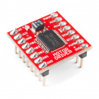
- 1x TB6612FNG Motor Driver (w/ Headers)
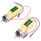
- 1x Hobby Gearmotor
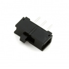
- 1x Switch
Didn't Get the Tinker Kit?
If you are conducting this experiment and didn't get the Tinker Kit, we suggest using these parts:


New Concepts
Switch
A switch is a component that controls the open-ness or closed-ness of an electric circuit. Just like the momentary buttons used in earlier circuits, a switch can only exist in one of two states: open or closed. However, a switch is different in that it will stay in the position it was last in until it is switched again.

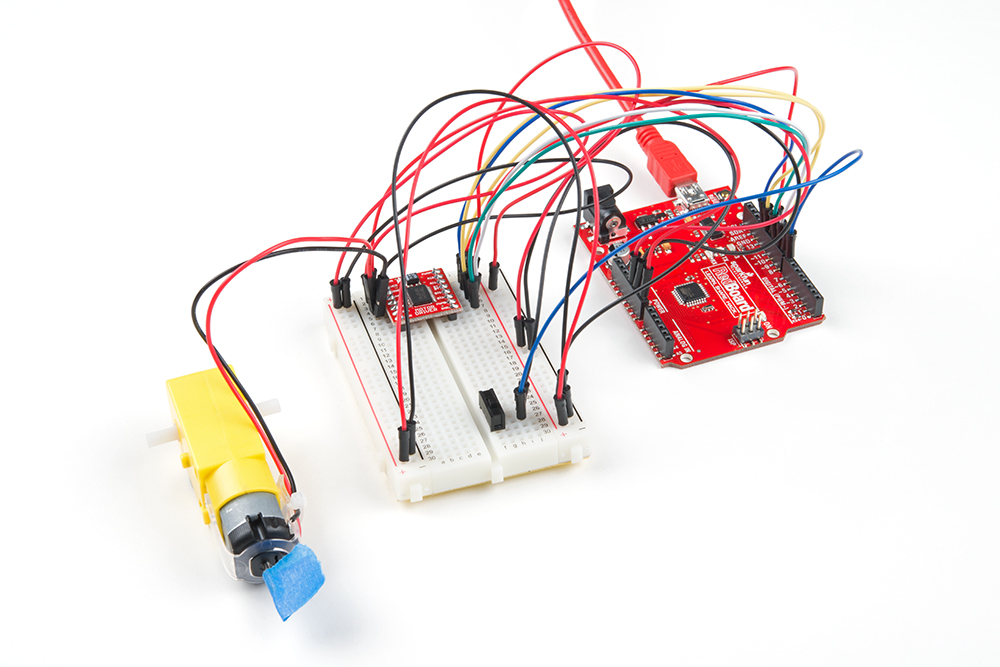
Hardware Hookup
| Polarized Components | Pay special attention to the component’s markings indicating how to place it on the breadboard. Polarized components can only be connected to a circuit in one direction. |
Ready to start hooking everything up? Check out the circuit diagram and hookup table below to see how everything is connected.
Circuit Diagram
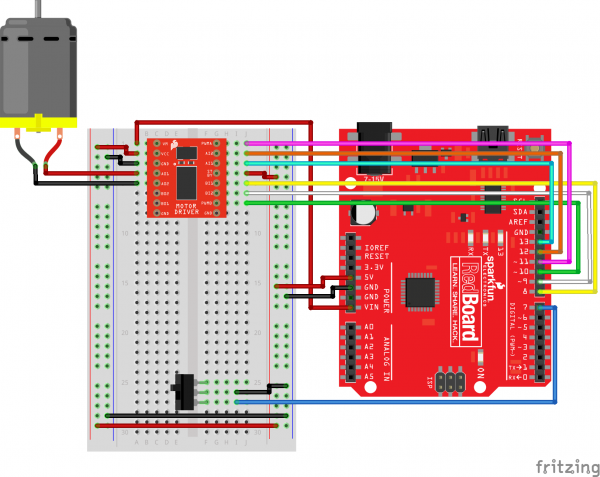
Hookup Table
| Component | RedBoard | Breadboard | Breadboard | Breadboard |
|---|---|---|---|---|
| Jumper Wire | 5V | 5V Rail ( + ) | ||
| Jumper Wire | GND | GND Rail ( - ) | ||
| Jumper Wire | 5V Rail ( + ) | 5V Rail ( + ) | ||
| Jumper Wire | GND Rail ( - ) | GND Rail ( - ) | ||
| Jumper Wire | VIN | A1 | ||
| Motor Driver | C1-C8 (VM on C1) | G1-G8 (PWMA on G1) | ||
| Jumper Wire | A2 | 5V Rail ( + ) | ||
| Jumper Wire | A3 | GND Rail ( - ) | ||
| Jumper Wire | Digital Pin 8 | J5 | ||
| Jumper Wire | Digital Pin 9 | J6 | ||
| Jumper Wire | Digital Pin 10 | J7 | ||
| Jumper Wire | J4 | 5V Rail ( + ) | ||
| Jumper Wire | Digital Pin 11 | J1 | ||
| Jumper Wire | Digital Pin 12 | J2 | ||
| Jumper Wire | Digital Pin 13 | J3 | ||
| Motor | A4 (Red +) | A5 (Black -) | ||
| Switch | F25 | F26 | F27 | |
| Jumper Wire | I26 | GND Rail ( - ) | ||
| Jumper Wire | Digital Pin 7 | I27 |
Open the Sketch
Copy and paste the following code into the Arduino IDE. Hit upload, and see what happens!
language:cpp
/*
SparkFun Tinker Kit
Circuit 11: Driving a Motor w/ Inputs

Learn how to control one motor with the motor driver with a switch and input from a serial monitor.

This sketch was written by SparkFun Electronics, with lots of help from the Arduino community.
This code is completely free for any use.

View circuit diagram and instructions at: https://learn.sparkfun.com/tutorials/activity-guide-for-sparkfun-tinker-kit
Download drawings and code at: https://github.com/sparkfun/SparkFun_Tinker_Kit_Code/
*/

//PIN VARIABLES
//the motor will be controlled by the motor A pins on the motor driver
const int AIN1 = 13;           //control pin 1 on the motor driver for the right motor
const int AIN2 = 12;            //control pin 2 on the motor driver for the right motor
const int PWMA = 11;            //speed control pin on the motor driver for the right motor

int switchPin = 7;             //switch to turn the robot on and off

//VARIABLES
int motorSpeed = 0;       //starting speed for the motor

void setup() {
  pinMode(switchPin, INPUT_PULLUP);   //set this as a pullup to sense whether the switch is flipped

  //set the motor contro pins as outputs
  pinMode(AIN1, OUTPUT);
  pinMode(AIN2, OUTPUT);
  pinMode(PWMA, OUTPUT);

  Serial.begin(9600);                       //begin serial communication with the computer

  Serial.println("Enter motor speed (0-255)... ");    //Prompt to get input in the serial monitor.
}

void loop() {

  if (Serial.available() > 0){          //if the user has entered something in the serial monitor
    motorSpeed = Serial.parseInt();     //set the motor speed equal to the number in the serial message

    Serial.print("Motor Speed: ");      //print the speed that the motor is set to run at
    Serial.println(motorSpeed);
  }

  if(digitalRead(7) == LOW){            //if the switch is on...
      spinMotor(motorSpeed);
  } else{                               //if the switch is off...
      spinMotor(0);                   //turn the motor off
  }


}

/********************************************************************************/
void spinMotor(int motorSpeed)                       //function for driving the right motor
{
  if (motorSpeed > 0)                                 //if the motor should drive forward (positive speed)
  {
    digitalWrite(AIN1, HIGH);                         //set pin 1 to high
    digitalWrite(AIN2, LOW);                          //set pin 2 to low
  }
  else if (motorSpeed < 0)                            //if the motor should drive backwar (negative speed)
  {
    digitalWrite(AIN1, LOW);                          //set pin 1 to low
    digitalWrite(AIN2, HIGH);                         //set pin 2 to high
  }
  else                                                //if the motor should stop
  {
    digitalWrite(AIN1, LOW);                          //set pin 1 to low
    digitalWrite(AIN2, LOW);                          //set pin 2 to low
  }
  analogWrite(PWMA, abs(motorSpeed));                 //now that the motor direction is set, drive it at the entered speed
}
What You Should See
When you flip the switch, the motor will turn on and spin at the speed set by the motor speed variable (default is 0). By opening the serial monitor and sending numbers, you can change the speed of the motor. Any number from about 130 to 255 or -130 to -255 will work, though changes in the speed will be hard to notice. Send the number 0 to stop the motor. Adding a piece of tape to the motor shaft makes it easier to see it spinning.
Program Overview
- Check to see if a command has been sent through the Serial Monitor. If a command has been sent, then set the motor speed to the number that was sent over the Serial Monitor.
- Check to see if the switch is ON or OFF. a. If the switch is ON, drive the motor at the motor speed. b. If the switch is OFF, stop the motor.
Code to Note
| Code | Description |
|---|---|
Parsing Integers:Serial.parseInt(); | parseInt() receives integer numbers from the serial monitor. It returns the value of the number that it receives, so you can use it like a variable. |
Serial Available:Serial.available(); | Serial.available() checks how many bytes of data are being sent to the RedBoard. If it is greater than 0, then a message has been sent. It can be used in an if statement to run code only when a command has been received. |
Coding Challenges
| Challenge | Description |
|---|---|
| Make the switch change directions | Change the code so that the position of the switch changes the direction of the motor instead of turning it on and off. |
| Replace the switch with a button | Try wiring a button into the circuit instead of the sliding switch. Now the motor only turns on when you push the button. |
| Replace the switch with a sensor | Try changing the code so that the motor is activated by another sensor, like the photoresistor. |
Troubleshooting
| Problem | Solution |
|---|---|
| Motor not spinning | Check the wiring to the motor driver. There are a lot of connections, and it’s easy to mix one of them up with another. If it is still not working, you can test the B channel by moving you motor. (Black wire to A6, Red wire to A7). You’ll need to change the code as well. |
| Motor spins but then stops | In the Serial Monitor, make sure you have No line ending selected in the drop down menu next to the Baud Rate drop down menu. |
| Switch not working | Make sure that you are hooked up to the middle pin and one side pin on the switch. |
| Still not working? | Jumper wires unfortunately can go "bad" from getting bent too much. The copper wire inside can break, leaving an open connection in your circuit. If you are certain that your circuit is wired correctly and that your code is error-free and uploaded but you are still encountering issues, try replacing one or more of the jumper wires for the component that is not working. |