Activity Guide for SparkFun Tinker Kit
This Tutorial is Retired!
This tutorial covers concepts or technologies that are no longer current. It's still here for you to read and enjoy, but may not be as useful as our newest tutorials.
View the updated tutorial: Tinker Kit Circuit Guide
 Joel_E_B,
  bboyho
 Circuit 4: RGB Night-Light
In this circuit, you'll take the night-light concept to the next level by adding an RGB LED, which is three differently colored Light-Emitting Diodes (LEDs) built into one component. RGB stands for Red, Green and Blue, and these three colors can be combined to create any color of the rainbow!
Parts Needed
You will need the following parts:
- 1x Breadboard
- 1x SparkFun RedBoard
- 12x Jumper Wires
- 1x LED - RGB Diffused Common Cathode
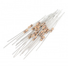
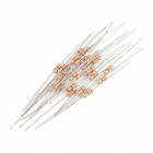
- 3x 330Ω Resistor
- 1x 10K Potentiometer
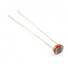
- 1x Photoresistor
- 1x 10kΩ Resistor
Didn't Get the Tinker Kit?
If you are conducting this experiment and didn't get the Tinker Kit, we suggest using these parts:


New Components
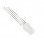
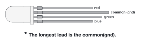
RGB LED
An RGB LED is actually three small LEDs --- one red, one green and one blue --- inside a normal LED housing. The RGB LED included in this kit has all the internal LEDs share the same ground wire, so there are four legs in total. To turn one color on, ensure ground is connected, then power one of the legs just as you would a regular LED. If you turn on more than one color at a time, you will see the colors start to blend together to form a new color.
New Concepts
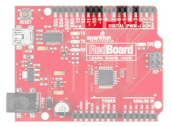
Analog Output (Pulse-width Modulation)
You can use the digitalWrite() command to turn pins on the RedBoard on (5V) or off (0V), but what if you want to output 2.5V? The RedBoard doesn't have an Analog Output, but it is really good at switching some digital pins on and off fast enough to simulate an analog output. analogWrite() can output 2.5 volts by quickly switching a pin on and off so that the pin is only on 50 percent of the time (50% of 5V is 2.5V). By changing the percent of time that a pin is on, from 0 percent (always off) to 100 percent (always on), analogWrite() can output any voltage between 0 and 5V. This is what is known as pulse-width modulation (or PWM). By using PWM, you can create many different colors with the RGB LED.
analogWrite() can only used on these pins.
Creating Your Own Simple Functions
When programmers want to use a piece of code over and over again, they write a function. The simplest functions are just chunks of code that you give a name to. When you want to run that code, you can “call” the function by typing its name, instead of writing out all of the code. More complicated functions take and return pieces of information from the program (we call these pieces of information parameters). In this circuit, you'll write functions to turn the RGB LED different colors by just typing that color's name.
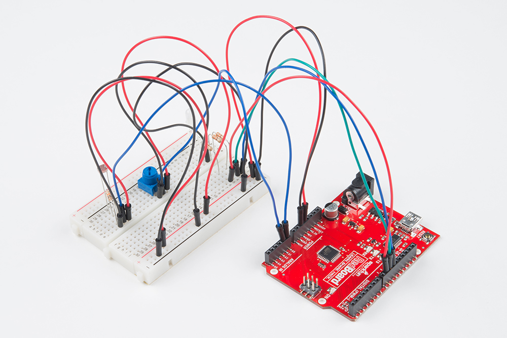
Hardware Hookup
| Polarized Components | Pay special attention to the component’s markings indicating how to place it on the breadboard. Polarized components can only be connected to a circuit in one direction. |
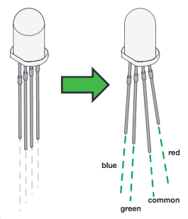
Just like a regular LED, an RGB LED is polarized and only allows electricity to flow in one direction. Pay close attention to the flat edge and to the different length leads. Both are indicators to help orient the LED correctly.
Ready to start hooking everything up? Check out the circuit diagram and hookup table below to see how everything is connected.
Circuit Diagram
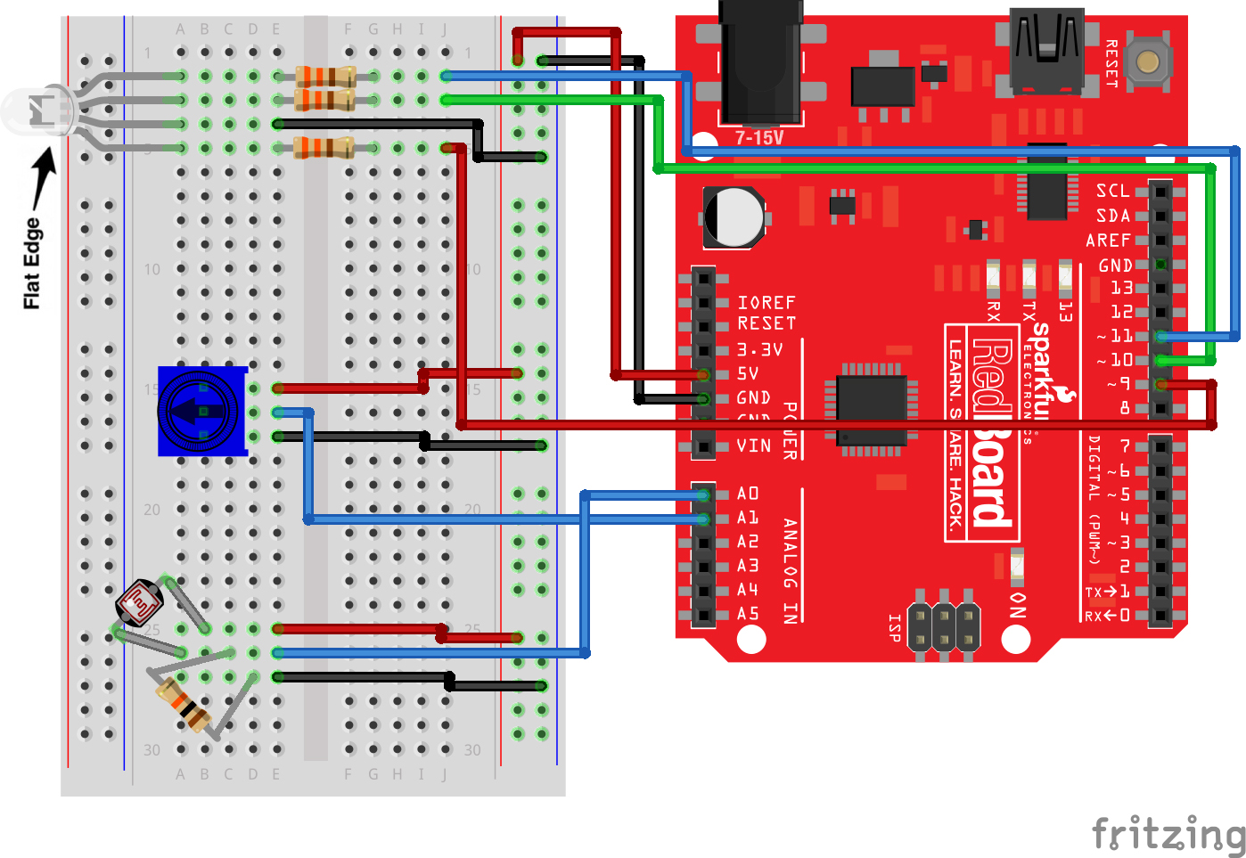
Hookup Table
| Component | RedBoard | Breadboard | Breadboard | Breadboard | Breadboard |
|---|---|---|---|---|---|
| RGB LED | A5 (RED) | A4 (GND) | A3 (GREEN) | A2 (BLUE) | |
| 330Ω Resistor (orange, orange, brown) |
E2 | F2 | |||
| 330Ω Resistor (orange, orange, brown) |
E3 | F3 | |||
| 330Ω Resistor (orange, orange, brown) |
E5 | F5 | |||
| Jumper Wire | E4 | GND Rail ( - ) | |||
| Jumper Wire | Digital Pin 9 | J5 | |||
| Jumper Wire | Digital Pin 10 | J3 | |||
| Jumper Wire | Digital Pin 11 | J2 | |||
| Jumper Wire | 5V | 5V Rail ( + ) | |||
| Jumper Wire | GND | GND Rail ( - ) | |||
| Potentiometer | B15 | B16 | B17 | ||
| Jumper Wire | Analog Pin 1 (A1) | E16 | |||
| Jumper Wire | E15 | 5V Rail ( + ) | |||
| Jumper Wire | E17 | GND Rail ( - ) | |||
| Photoresistor | A26 | B25 | |||
| 10kΩ Resistor (brown, black, orange) |
C26 | D27 | |||
| Jumper Wire | Analog Pin 0 (A0) | E26 | |||
| Jumper Wire | E25 | 5V Rail ( + ) | |||
| Jumper Wire | E27 | GND Rail ( - ) |
Open the Sketch
Copy and paste the following code into the Arduino IDE. Hit upload, and see what happens!
language:cpp
/*
SparkFun Tinker Kit
Circuit 4: RGB Night-Light

Turns an RGB LED on or off based on the light level read by a photoresistor.
Change colors by turning the potentiometer.

This sketch was written by SparkFun Electronics, with lots of help from the Arduino community.
This code is completely free for any use.

View circuit diagram and instructions at: https://learn.sparkfun.com/tutorials/activity-guide-for-sparkfun-tinker-kit/
Download drawings and code at: https://github.com/sparkfun/SparkFun_Tinker_Kit_Code
 */

int photoresistor;          //variable for storing the photoresistor value
int potentiometer;          //variable for storing the photoresistor value
int threshold = 700;            //if the photoresistor reading is lower than this value the light wil turn on

//LEDs are connected to these pins
int RedPin = 9;
int GreenPin = 10;
int BluePin = 11;

void setup() {
  Serial.begin(9600);           //start a serial connection with the computer

  //set the LED pins to output
  pinMode(RedPin,OUTPUT);
  pinMode(GreenPin,OUTPUT);
  pinMode(BluePin,OUTPUT);
}

void loop() {

  photoresistor = analogRead(A0);         //read the value of the photoresistor
  potentiometer = analogRead(A1);

  Serial.print("Photoresistor value:");
  Serial.print(photoresistor);          //print the photoresistor value to the serial monitor
  Serial.print("  Potentiometer value:");
  Serial.println(potentiometer);          //print the photoresistor value to the serial monitor

  if(photoresistor < threshold){          //if it's dark (the photoresistor value is below the threshold) turn the LED on
    //These nested if staments check for a variety of ranges and
    //call different functions based on the current potentiometer value.
    //Those functions are found at the bottom of the sketch.
    if(potentiometer > 0 && potentiometer <= 150)
      red();
    if(potentiometer > 150 && potentiometer <= 300)
      orange();
    if(potentiometer > 300 && potentiometer <= 450)
      yellow();
    if(potentiometer > 450 && potentiometer <= 600)
      green();
    if(potentiometer > 600 && potentiometer <= 750)
      cyan();
    if(potentiometer > 750 && potentiometer <= 900)
      blue();
    if(potentiometer > 900)
      magenta();
  }
  else {                                //if it isn't dark turn the LED off

    turnOff();                            //call the turn off function

  }

  delay(100);                             //short delay so that the printout is easier to read
}

void red (){

    //set the LED pins to values that make red
    analogWrite(RedPin, 100);
    analogWrite(GreenPin, 0);
    analogWrite(BluePin, 0);
}
void orange (){

    //set the LED pins to values that make orange
    analogWrite(RedPin, 100);
    analogWrite(GreenPin, 50);
    analogWrite(BluePin, 0);
}
void yellow (){

    //set the LED pins to values that make yellow
    analogWrite(RedPin, 100);
    analogWrite(GreenPin, 100);
    analogWrite(BluePin, 0);
}
void green (){

    //set the LED pins to values that make green
    analogWrite(RedPin, 0);
    analogWrite(GreenPin, 100);
    analogWrite(BluePin, 0);
}
void cyan (){

    //set the LED pins to values that make cyan
    analogWrite(RedPin, 0);
    analogWrite(GreenPin, 100);
    analogWrite(BluePin, 100);
}
void blue (){

    //set the LED pins to values that make blue
    analogWrite(RedPin, 0);
    analogWrite(GreenPin, 0);
    analogWrite(BluePin, 100);
}
void magenta (){

    //set the LED pins to values that make magenta
    analogWrite(RedPin, 100);
    analogWrite(GreenPin, 0);
    analogWrite(BluePin, 100);
}
void turnOff (){

    //set all three LED pins to 0 or OFF
    analogWrite(RedPin, 0);
    analogWrite(GreenPin, 0);
    analogWrite(BluePin, 0);
}
What You Should See
This sketch is not dissimilar from the last. It reads the value from the photoresistor, compares it to a threshold value, and turns the RGB LED on or off accordingly. This time, however, we've added a potentiometer back into the circuit. When you twist the pot, you should see the color of the RGB LED change based on the pot's value.
Open the Serial Monitor. The value being read by the light sensor should be printed several times a second. When you turn out the lights or cover the sensor, the LED will shine whatever color your programmed in your color function. Next to the light value, you'll see the potentiometer value print out as well.
Program Overview
- Store the light level from pin A0 in the variable
photoresistor. - Store the potentiometer value from pin A1 in the variable
potentiometer. - If the light level variable is above the
threshold, call the function that turns the RGB LED off. - If the light level variable is below the
threshold, call one of the color functions to turn the RGB LED on. - If
potentiometeris between 0 and 150, turn the RGB LED on red. - If
potentiometeris between 151 and 300, turn the RGB LED on orange. - If
potentiometeris between 301 and 450, turn the RGB LED on yellow. - If
potentiometeris between 451 and 600, turn the RGB LED on green. - If
potentiometeris between 601 and 750, turn the RGB LED on cyan. - If
potentiometeris between 751 and 900, turn the RGB LED on blue. - If
potentiometeris greater than 900, turn the RGB LED on magenta.
Code to Note
| Code | Description |
|---|---|
Analog Output (PWM):analogWrite(RedPin, 100); |
The analogWrite() function outputs a voltage between 0 and 5V on a pin. The function breaks the range between 0 and 5V into 255 little steps. Note that we are not turning the LED on to full brightness (255) in this code so that the night-light is not too bright. Feel free to change these values and see what happens. |
Nested if Statements:if(logic statement) {if(logic statement) {code to be run if the logic statement is true}if(logic statement) {code to be run if the logic statement is true}} |
A nested if statement is one or more if statements "nested" inside of another if statement. If the parent if statement is true, then the code looks at each of the nested if statements and executes any that are true. If the parent if statement is false, then none of the nested statements will execute. |
More Logical Operators:if(potentiometer > 0 && potentiometer <= 150) |
These if statements are checking for two conditions by using the AND (&&) operator. In this line, the if statement will only be true if the value of the variable potentiometer is greater than 0 AND if the value is less than or equal to 150. By using &&, the program allows the LED to have many color states. |
Defining a Function:void function_name () {
    code to run inside function
}
|
This simple version of a function executes the code inside the curly brackets whenever the name is written in the main program. |
Calling a Function:function_name();
|
Calls a function that you have created. In a later circuit, you will learn how to make more complicated functions that take data from the main program (these pieces of data are called parameters). |
Coding Challenges
| Challenge | Description |
|---|---|
| Add more colors | You can create many more colors with the RGB LED. Use the analogWrite() function to blend different values of red, green and blue together to make even more colors. You can divide the potentiometer value up more and make more nested if statements so that you can have more colors as you twist the knob. |
| Multi color blink | Try using delays and multiple color functions to have your RGB LED change between multiple colors. |
| Change the threshold | Try setting your threshold variable by reading the value of a potentiometer with analogRead(). By turning the potentiometer, you can then change the threshold level and adjust your night-light for different rooms. |
| Fading the LED | Try using a loop with the analogWrite() to get your LED to pulse gently or smoothly transition between colors. |
Troubleshooting
| Problem | Solution |
|---|---|
| The LED never turns on or off | Open the Serial Monitor in Arduino and make sure that your photoresistor is returning values between 0 and 1023. Try covering the photoresistor; the values should change. If they do not change, check the wiring of the photoresistor.
If your photoresistor is working correctly, make sure that your threshold variable sits in between the value that the photoresistor reads when it is bright and the value that the photoresistor reads when it is dark (e.g., bright = 850, dark = 600, threshold = 700). |
| My LED doesn’t show the colors that I expect | Make sure that all three of the pins driving your RGB LED are set to OUTPUT, using the pinMode() command in the setup section of the code. Then make sure that each LED is wired properly. |
| Nothing is printing in the Serial Monitor | Try unplugging your USB cable and plugging it back in. In the Arduino IDE, go to Tools > Port, and make sure that you select the right port. |