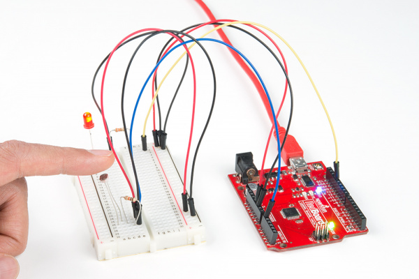
Activity Guide for SparkFun Tinker Kit
This Tutorial is Retired!
This tutorial covers concepts or technologies that are no longer current. It's still here for you to read and enjoy, but may not be as useful as our newest tutorials.
View the updated tutorial: Tinker Kit Circuit Guide
Circuit 3: Photoresistor
In the previous circuit, you got to use a potentiometer, which varies resistance based on the twisting of a knob. In this circuit you’ll be using a photoresistor, which changes resistance based on how much light the sensor receives. Using this sensor you can make a simple night-light that turns on when the room gets dark and turns off when it is bright.
Parts Needed
You will need the following parts:
- 1x Breadboard
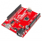
- 1x SparkFun RedBoard
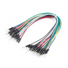
- 7x Jumper Wires
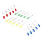
- 1x Red LED
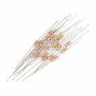
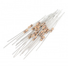
- 1x 330Ω Resistor
- 1x Photoresistor
- 1x 10kΩ Resistor
Didn't Get the Tinker Kit?
If you are conducting this experiment and didn't get the Tinker Kit, we suggest using these parts:
New Components
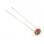
Photoresistor
Photoresistors, or photocells, are light-sensitive, variable resistors. As more light shines on the sensor’s head, the resistance between its two terminals decreases. They’re an easy-to-use component in projects that require ambient-light sensing.
New Concepts
Analog to Digital Conversion
The world we live in is analog, but the RedBoard lives in a digital world. In order to have the RedBoard sense analog signals, we must first pass them through an Analog to Digital Converter (or ADC). The six analog inputs (A0--A5) covered in the last circuit all use an ADC. These pins "sample" the analog signal and create a digital signal for the microcontroller to interpret. The "resolution" of this signal is based on the resolution of the ADC. In the case of the RedBoard, that resolution is 10-bit. With a 10-bit ADC, we get 2 ^ 10 = 1024 possible values, which is why the analog signal varies between 0 and 1023.
Voltage Divider Continued
Since the RedBoard can’t directly interpret resistance (rather, it reads voltage), we need to use a voltage divider to use our photoresistor, a part that doesn't output voltage. The resistance of the photoresistor changes as it gets darker or lighter. That changes the amount of voltage that is read on the analog pin, which "divides" the voltage, 5V in this case. That divided voltage is then read on the analog to digital converter.
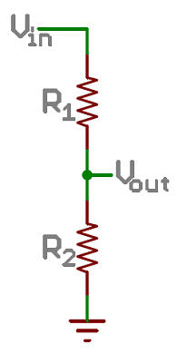

The voltage divider equation assumes that you know three values of the above circuit: the input voltage (Vin), and both resistor values (R1 and R2). Given those values, we can use this equation to find the output voltage (Vout):
If R1 is a constant value (the resistor) and R2 fluctuates (the photoresistor), the amount of voltage measured on the Vout pin will also fluctuate.
Hardware Hookup
Note that the photoresistor is not polarized. It can be inserted in either direction.
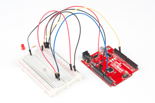
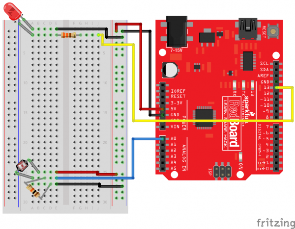
Ready to start hooking everything up? Check out the circuit diagram and hookup table below to see how everything is connected.
Circuit Diagram
Hookup Table
| Component | RedBoard | Breadboard | Breadboard |
|---|---|---|---|
| Jumper Wire | 5V | 5V Rail ( + ) | |
| Jumper Wire | GND | GND Rail ( - ) | |
| LED | A1 LED ( - ) | A2 LED ( + ) | |
| 330Ω Resistor (orange, orange, brown) |
E2 | F2 | |
| Jumper Wire | E1 | GND Rail ( - ) | |
| Jumper Wire | Digital Pin 13 | J2 | |
| Photoresistor | A26 | B25 | |
| 10kΩ Resistor (brown, black, orange) |
C26 | D27 | |
| Jumper Wire | Analog Pin 0 (A0) | E26 | |
| Jumper Wire | E25 | 5V Rail ( + ) | |
| Jumper Wire | E27 | GND Rail ( - ) |
Open the Sketch
Copy and paste the following code into the Arduino IDE. Hit upload, and see what happens!
language:cpp
/*
SparkFun Tinker Kit
Circuit 3: Photoresistor

Use a photoresistor to monitor how bright a room is, and turn an LED on when it gets dark.

This sketch was written by SparkFun Electronics, with lots of help from the Arduino community.
This code is completely free for any use.

View circuit diagram and instructions at: https://learn.sparkfun.com/tutorials/activity-guide-for-sparkfun-tinker-kit/
Download drawings and code at: https://github.com/sparkfun/SparkFun_Tinker_Kit_Code
*/

int photoresistor = 0;              //this variable will hold a value based on the position of the knob
int threshold = 750;                //if the photoresistor reading is below this value the light will turn on

void setup()
{
  Serial.begin(9600);               //start a serial connection with the computer

  pinMode(13, OUTPUT);              //set pin 13 as an output that can be set to HIGH or LOW
}

void loop()
{
  //read the position of the knob
  photoresistor = analogRead(A0);   //set photoresistor to a number between 0 and 1023 based on how far the knob is turned
  Serial.println(photoresistor);    //print the value of photoresistor in the serial monitor on the computer

  //if the photoresistor value is below the threshold turn the light on, otherwise turn it off
  if (photoresistor < threshold){
    digitalWrite(13, HIGH);         // Turn on the LED
  } else{
    digitalWrite(13, LOW);          // Turn off the LED
  }

  delay(100);                       //short delay to make the printout easier to read
}
What You Should See
The program stores the light level in a variable, photoresistor. Then, using an if/else statement, the program checks to see what it should do with the LED. If the variable is above the threshold (it’s bright), turn the LED off.
If the variable is below the threshold (it’s dark), turn the LED on. You now have just built your own night-light!
Open the Serial Monitor in Arduino. The value of the photoresistor should be printed every so often. When the photoresistor value drops below the threshold value set in the code, the LED should turn on (you can cover the photoresistor with your finger to make the value drop).
Program Overview
- Store the light level in the variable
photoresistor. - If the value of
photoresistoris above thethreshold(it’s bright), turn the LED off. - If the value of
photoresistoris below thethreshold(it’s dark), turn the LED on.
Code to Note
| Code | Description |
|---|---|
If/else Statements:if(logic statement) {code to be run if the logic statement is true}else {code to be run if the logic statement is false
} |
The if/else statement lets your code react to the world by running one set of code when the logic statement in the round brackets is true and another set of code when the logic statement is false. For example, this sketch uses an if statement to turn the LED on when it is dark, and turn the LED off when it is light. |
Logical Operators:(photoresistor < threshold) |
Programmers use logic statements to translate things that happen in the real world into code. Logic statements use logical operators such as 'equal to' (==), 'greater than' (>), and 'less than' (<), to make comparisons. When the comparison is true (e.g., 4 < 5) then the logic statement is true. When the comparison is false (e.g., 5 < 4) then the logic statement is false. This example is asking whether the variable photoresistor is less than the variable threshold. |
Coding Challenges
| Challenge | Description |
|---|---|
| Response Pattern | Right now your if statement turns the LED on when it gets dark, but you can also use the light sensor like a no-touch button. Try using digitalWrite() and delay() to make the LED blink a pattern when the light level drops, then calibrate the threshold variable in the code so that the blink pattern triggers when you wave your hand over the sensor. |
| Replace 10KΩ Resistor with LED | Alter the circuit be replacing the 10KΩ resistor with an LED (the negative leg should connect to GND). Now what happens when you place your finger over the photoresistor? This is a great way to see Ohm's law in action by visualizing the change in resistance's affect on the current flowing through the LED. |
Troubleshooting
| Problem | Solution |
|---|---|
| The light never turns on or always stays on | Start the Serial Monitor in Arduino. Look at the value that the photoresistor is reading in a bright room (e.g., 915). Cover the photoresistor, or turn the lights off. Then look at the new value that the photoresistor is reading (e.g., 550). Set the threshold in between these two numbers (e.g., 700) so that the reading is above the threshold when the lights are on and below the threshold when the lights are off. |
| Nothing is printing in the Serial Monitor | Try unplugging your USB cable and plugging it back in. In the Arduino IDE, go to Tools > Port, and make sure that you select the right port. |
