Wireless Audio Bluetooth Adapter w/ BC127
 bboyho
Hardware Hookup
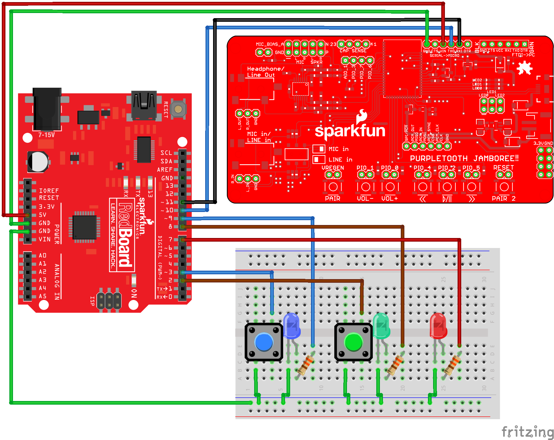
After configuring the BC127 and testing the BC127, I decided to automate the commands with button presses using a RedBoard programmed with Arduino. The code was written and tested on a breadboard before soldering anything together as shown below:
Soldering the Metal Pushbuttons
Once the code was tested and stable, I decided use panel mount momentary metal pushbuttons. The momentary push bushbutton acts like a normal momentary push button if you connect to the normally open (NO1) and common pin (C1). As a bonus, there are pins labeled "+" and "-" that connect to an LED ring.

I found that the metal pushbuttons also included a built-in resistor from user emc2, so the 330Ω resistor was not included when soldering to the buttons. Testing with a variable power supply, the LED did not appear to act like a short circuit when 5V was applied. The red LED was also removed since the project would always be connected to a power supply.
| Component | Component Pin | Arduino I/O Pin |
|---|---|---|
| Blue Momentary Metal Pushbutton | + : LED Anode Side | 9 |
| NC1: Normally Closed Pin | ||
| NO1: Normally Open Pin | 3 | |
| C1: Common Pin | GND | |
| -: LED Cathode Side | GND | |
| Green Momentary Metal Pushbutton | + : LED Anode Side | 8 |
| NC1: Normally Closed Pin | ||
| NO1: Normally Open Pin | 2 | |
| C1: Common Pin | GND | |
| -: LED Cathode Side | GND | |
| PurpleTooth Jamboree BC127 | GND | GND |
| VIN | 5V | |
| TXO | 10 | |
| RXI | 11 |
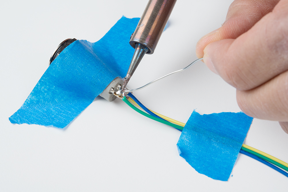
To connect the metal pushbuttons to the RedBoard's female headers, 12" male jumper wires were cut in half and stripped using wire strippers. The exposed wire was threaded and soldered to each metal pushbutton's pin. To assist in soldering, tape was used to hold down the wire and metal pushbutton.

An intentional solder jumper was added between the "-" and COM1 pin since both pins needed to be connected to GND.
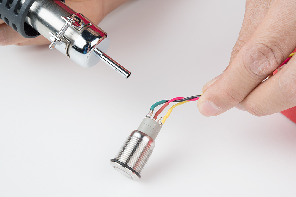
After testing the connections and LED with a multimeter, the solder joint was sealed with heatshrink using a hot air rework station.
Enclosure
Once the parts were soldered together, I wanted to make a quick enclosure. I decided to use a red SparkFun cardboard box to hold and secure the parts.
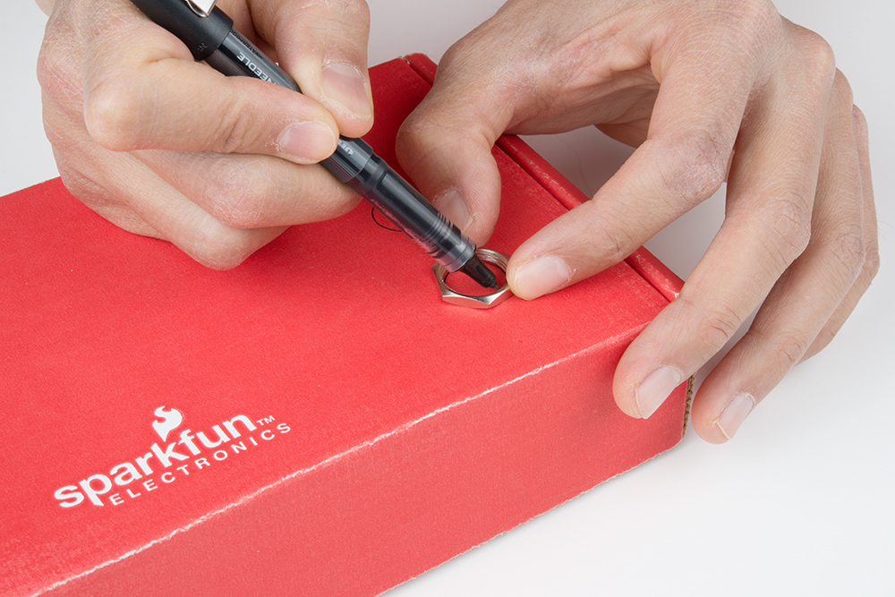
Using the metal pushbutton's provided hex nut, two circles were drawn on the top of the box.
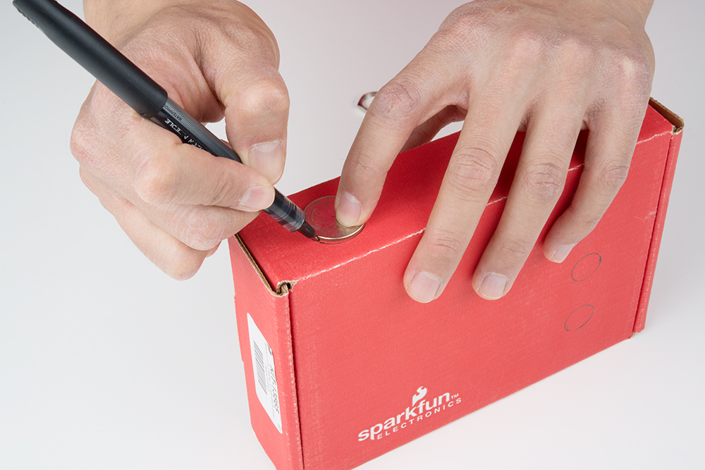
Using a coin, an additional hole was drawn for the power and audio cables.
Using a hobby knife, the holes were carefully cut. There was not a lot of tolerance available for the metal pushbutton's flange. A smaller hole was cut within the circle and adjusted as necessary when installing the metal pushbutton.

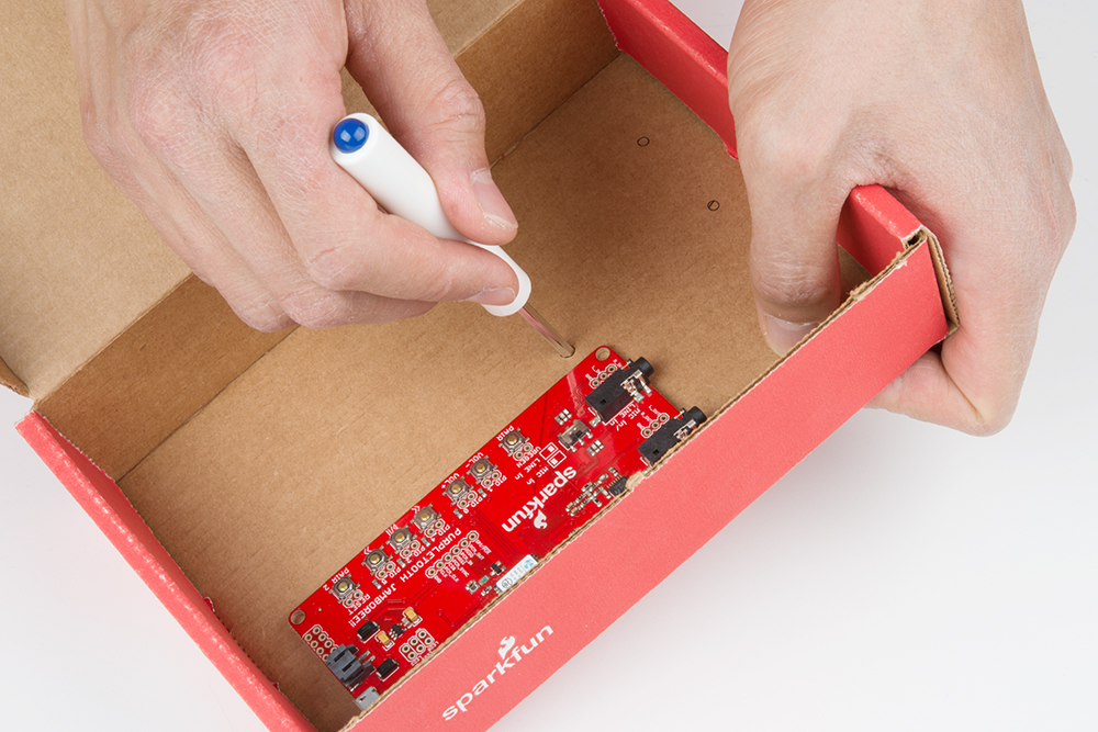
Next up were the mounting holes for the RedBoard and Purpletooth Jamboree. I planned the location for each component and made sure that the components did not interfere with each other when the box was closed. Holes were drawn for the mounting hole locations and created using the "+" side of a mini screwdriver.
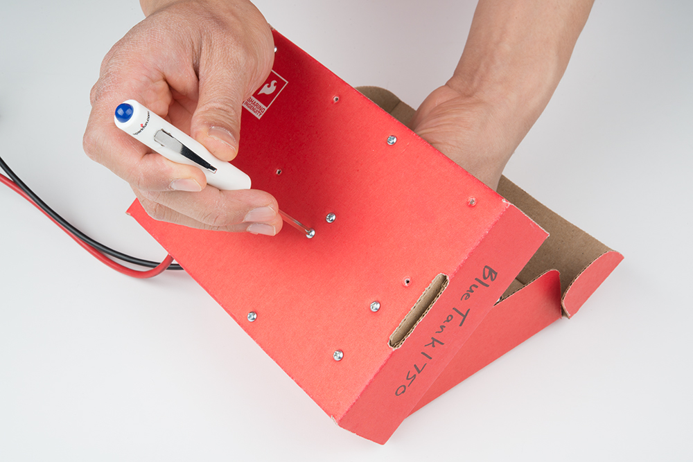
Two screws and a standoff were used for each mounting hole. The mini screwdriver was used to secure the hardware.
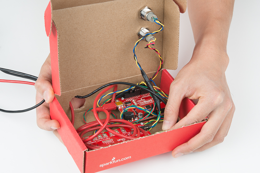
After braiding the wires and wiring the components together, the metal pushbuttons were mounted and secured with their respective hex nut. This was a good time to add the mini-B USB and audio cable.

Before closing the box, I made sure that the wires and components had enough room and were not causing any stress to the connections.
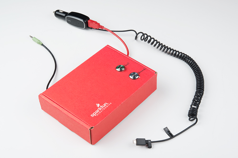
For power, I decided to use a 5V car adapter with a USB port. I made sure to label the buttons and the Bluetooth's name before connecting it to my car.