WiFly Shield Hookup Guide
 Joel_E_B,
  CTaylor
Hardware Overview

The WiFly Shield consists of two major components:
The WiFly module communicates via its UART to the SC16IS750 bridge chip, which in turn communicates with the Arduino via SPI.

This allows the WiFly module to communicate with the Arduino at high speed without using the Arduino’s UART so that the Arduino can still communicate with a serial terminal. Any communication from the WiFly to the Arduino (or vice versa) must be sent through the SC16IS50.
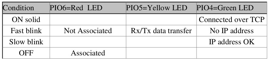
The WiFly module is connected to four indicator LEDs through its I/O pins. These indicator LEDs will blink at different rates depending on the state of the module. They can provide a lot of information to the user about the state of the module without the user having to connect the device to a serial terminal. For more information on the behavior of the LEDs, see the RN-131 Reference Guide.
The WiFly module is also connected to four jumpers. The jumper PIO9 is a special jumper and is used to put the module into adhoc mode. If you would like to communicate directly with the WiFly from a computer in an adhoc fashion, short the PIO9 jumper with solder.
Last, the WiFly has a small prototyping area to connect any other components you'd like. You could add additional LEDs, sensors, motors, or other bits to make your project come alive.
WiFly Breakout Board
You can also use the information in this tutorial to use the WiFly GSX Breakout. However, since the breakout board does not include an SPI-to-UART IC, you will have to either use a separate conversion chip or communicate directly to the WiFly module over the UART. Keep in mind that if you do use the Arduino's UART to communicate to the module, you will not be able to send back repsonses to the termial window unless you use a seperate UART (The Arduino mega has several UARTs or you can you the SoftwareSerial library on an Uno).