Vernier Shield Hookup Guide
 bri_huang
Example 2 - Photogate Timer
In many classrooms, a standard stopwatch or timer is used to measure the time elapsed for moving objects such as mousetrap car races, rolling dynamics carts, or falling tennis balls.
These little stopwatches are great for most simple activities, but for many investigations and experiments, human reaction time and classroom distractions often introduce too much error and uncertainty to collect repeatable results for students to draw clear conclusions from their data.
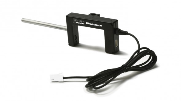
Integrating a photogate timer is one of the simplest and low-cost tools a teacher can use. A photogate is simply an infra-red LED and receiver pair. The photogate normally produces a HIGH signal on DIO0 when the gate is unblocked. When an object passes through the gate, the signal is LOW until the gate is unblocked again.
Integrating this with a very fast timer, we can achieve very reliable and precise timing results.
The Arduino UNO has a 16 MHz clock. Accounting for overhead events and extra needed clock cycles and such, the Arduino is capable of timing results with a precision better than +/- 1 uS.
This code example is interrupt driven and uses the micros() arduino command to return the number of microseconds since the start of the program. This number is stored in an unsigned long variable. This gives the program a maximum time limit of about 1 hour and 11 minutes before the counter wraps. Generally speaking, we're looking to capture the amount of time for a marble, toy car, or playing card to move through the gate.
This sketch simply outputs an event entry to the Serial Monitor with the Event #, the photogate state (Blocked or Unblocked), and the time since the start of the program.
language:c
    /*
 VernierPhotogateTimer (v 2013.12.09)
 Monitors a Vernier Photogate connected to BTD connector.

 This sketch lists the time in microseconds since the program started running.

 To ensure the greatest accuracy, this code is written using interrupts.
 For more information about using interrupts, see:
 http://playground.arduino.cc/Code/Interrupts

 For more details around using Arduino with Vernier see
 www.vernier.com/arduino.

 Modified by: B. Huang, SparkFun Electronics
 December 9, 2013

 This version incorporates a "circular" buffer of 150 elements and stores all events
 (blocking and unblocking) of the photogate to an precision of 1 us. In addition,
 the data is streamed to the Serial buffer and can be captured, copied, exported,
 and analyzed in your favorite analysis tool -- Graphical Analysis, LoggerPro, Excel,
 Google Sheets, Matlab, etc...

 */
#include <SoftwareSerial.h>

// mode variable definitions
#define GATE_MODE 1
#define PULSE_MODE 2
#define PENDULUM_MODE 3

#define bufferSize 150  // Sets the size of the circular buffer for storing interrupt data events. Increasing this may cause erratic behavior of the code.
#define DELIM '\t'   // this is the data delimitter. Default setting is a tab character ("\t")

const int baudRate = 9600;  // Baud rate for serial communications. Increase this for high data rate applications (i.e. smart pulley)

unsigned int refreshRate = 250;  // sets # of milliseconds between refreshes of LED Display

const int buttonPin = 12;   // default buttonPin on Vernier Shield
const int ledPin = 13;    // re-purposed pin 13 to tie to the Serial 7 Segment
const int photogatePin = 2; // default pin if plugged into Digital 1 on SparkFun Vernier Shield

/* The following variables are all used and modified by the code. These should not be changed or re-named. */
int mode = 1; // sets the default mode of operation
// Mode 1 -- Gate, Mode 2 -- Pulse, Mode 3 -- Pendulum

int lastState;
int currTimeDigits;
unsigned long currTime;
unsigned long timerOffset = 0;
unsigned int displayIndex; // the current item that has been displayed to the Serial Monitor from the data buffer.
unsigned int count;  // tracks the total # of data entries

char tempString[4];   // String buffer to store for sending to the serial 7 segment display

/* These variables are all accessed and modified by the interrupt handler "PhotogateEvent"
Variables used by the Interrupt handler must be defined as volatile. */
volatile int photogate = HIGH;
volatile int start = 0;  // 1 == start, 0 == stop
volatile unsigned int numBlocks;
volatile unsigned long startTime;  //Time in us
volatile unsigned long stopTime;  //Time in us
volatile byte dataIndex;
volatile byte displayCount;  // stores the number of items in data Buffer to be displayed
volatile byte state[bufferSize];
volatile unsigned long time_us[bufferSize]; // Time in us

void setup()
{
  attachInterrupt(0, photogateEvent, CHANGE); // photogate_event
  pinMode(buttonPin, INPUT_PULLUP);
  pinMode(ledPin, OUTPUT);
  Serial.begin(9600);           // set up Serial library at 9600 bps
  displayHeader();
};// end of setup

void loop ()
{
  // check for button press to change modes
  if (digitalRead(12) == LOW)
  {
    resetCount();

    while((digitalRead(buttonPin) == LOW)); // hold until button is released
    delay(10); // for de-bouncing
    displayHeader();
  } // if button is pressed

  if (displayCount > 0)  // only display to Serial monitor if an interrupt has added data to the data buffer.
  {
    count++;
    Serial.print(count);
    Serial.print(DELIM); //tab character
    Serial.print(state[displayIndex]);
    Serial.print(DELIM); //tab character
    Serial.print((time_us[displayIndex] - timerOffset) / 1E6, 6);  // at least 6 sig figs

    Serial.println();

    displayIndex++;
    if(displayIndex >= bufferSize)
    {
      displayIndex = 0;
    }
    displayCount--; // deduct one
  }
} // end of loop

void resetCount()
{
  dataIndex = 0;
  displayIndex = 0;
  count = 0;
  numBlocks = 0;
  start = 0;
  Serial.println();
  Serial.println("*****Reset*****");
  Serial.println();
  timerOffset = micros();

}

/*************************************************
 * photogateEvent()
 *
 * Interrupt service routine. Handles capturing
 * the time and saving this to memory when the
 * photogate issues an interrupt on pin 2.
 *
 * As it is currently written, the photogate
 * will only work on Digital Port 1.
 *************************************************/
void photogateEvent()
{
  time_us[dataIndex] = micros();

  photogate = digitalRead(photogatePin);

  if (photogate == 1)
  {
    state[dataIndex] = 0;  // reverses the result so that 1 = blocked, 0 = open
    digitalWrite(ledPin, LOW);  // turns the indicator LED off
  }
  else
  {
    state[dataIndex] = 1;                  // normal operation is 1 = open and 0 = blocked
    digitalWrite(ledPin, HIGH);   // turns the indicator LED on
  }
  displayCount++;  // add one to "to be displayed" buffer

  dataIndex++;
  if(dataIndex >= bufferSize)
  {
    dataIndex = 0;
  }
}

/*************************************************
 * displayHeader()
 *
 * Presents the data header to Serial Monitor
 * This data is tab delimitted and can be copied
 * and pasted directly into Excel or spreadsheet
 * / graphing program.
 *************************************************/
void displayHeader()
{
  Serial.println("Vernier Format 2");
  Serial.println();
  Serial.print("Event");
  Serial.print(DELIM);
  Serial.print("Blocked");
  Serial.print(DELIM);
  Serial.print("Time       ");
  Serial.println();

// Units
  Serial.print("#");
  Serial.print(DELIM);
  Serial.print("(n/a)");
  Serial.print(DELIM);
  Serial.print("(s)         ");
  Serial.println();


  Serial.println("--------------------------");
}
Data Output Format
The data is tab delimitted, and you can simply copy-paste this into your favorite data analysis program such as LoggerPro, Matlab, Google Sheets, or Excel.
Vernier Format 2

Event    Blocked    Time
#   (n/a)   (s)
--------------------------
1   1   1.885308
2   0   1.903900
3   1   1.908432
4   0   1.927056
5   1   1.945756
6   0   1.964332
7   1   1.980148
8   0   1.996724
Sensor Calibration and Verification - Falling Picket Fence
The Falling Picket Fence is a classic activity used in many physics classes. It extends and combines the concepts of average velocity to instantaneous velocity and explore uniform acceleration and the nature of the acceleration due to gravity.
A picket fence is nothing more than a clear piece of plastic with opaque bars spaced 5 centimeters apart (center-to-center).
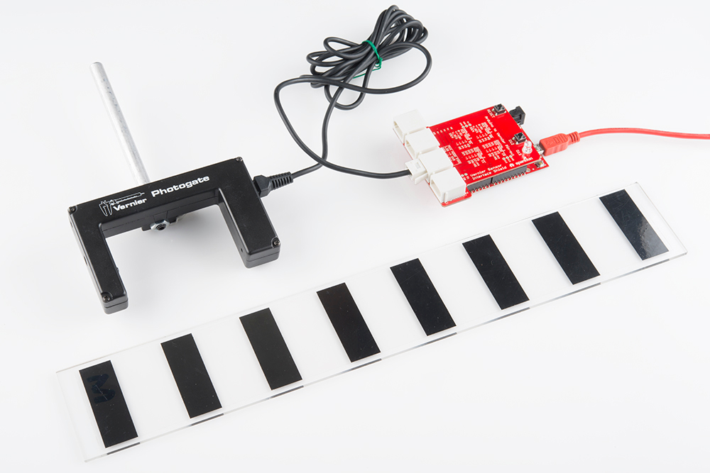
Dropping a picket fence near the surface of the Earth should accelerate uniformly at a rate of 9.8 m/s/s. I used this to verify and check the accuracy of the timing. I used the sample code from above and dropped a picket fence through the photogate, and here is the data it returned:
Vernier Format 2

Event   Blocked    Time
#   (n/a)   (s)
--------------------------
1   1   5.520980
2   0   5.542184
3   1   5.570784
4   0   5.584924
5   1   5.605876
6   0   5.617208
7   1   5.635028
8   0   5.644568
9   1   5.659904
10  0   5.668612
11  1   5.682448
12  0   5.690280
13  1   5.702860
14  0   5.710160
15  1   5.721872
16  0   5.728644
Clearly that's accelerating at 9.8 m/s/s, right?
Okay, you're right. It's about as clear as mud. It's just a bunch of numbers, but if you look closely, you can see that the time between events appears to be getting smaller and smaller. Ah, ha! It's speeding up! That's a good sign.
The raw data is difficult to understand without processing, so I created a sample worksheet that can be used in any class. The worksheet calculates the average velocity between blocking events.
Using the worksheet, I graphed velocity vs. time and found the slope.
|
Data Statistics slope: 9.78799 m/s/s intercept: 0.758978 m/s |
Is it right? Well - I try to avoid making right vs. wrong judgements in science. It is simply data, and all I can say is that it appears to agree with our existing assumptions and observations of the universe.
Other things you can do with photogates?
Check out the Vernier Photogate Timer Project tutorial.