Vernier Shield Hookup Guide
Introduction
As a former high school physics teacher, I taught nearly every unit using Vernier sensors in my classroom. Vernier has an extensive suite of sensors, easy-to-use software, and amazing support for all of their products.
I had great success using Vernier in my physics class, but I was looking for a solution that would enable me to use these same sensors in other classrooms where I did not have direct access to computers with LoggerPro software or the Vernier LabPro hardware.
Part of this journey led me to developing this low-cost photogate timer project. I had conceived this idea before starting here at SparkFun, and, once here, I was able to start this project to develop an Arduino shield that would allow us to quickly connect any Vernier probe to an Arduino.
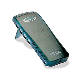
Vernier LabPro
This green box is a classic in many science classrooms. It makes a very pleasant, instantly recognizable tone when it's plugged into a computer.
In addition to the LabPro, Vernier also has a variety of other interfaces including the:
These interfaces are great solutions for data collection and automation in the classroom. They are simple to use and integrate directly with Vernier's LoggerPro software platform. With the increased access to of low-cost micro-controllers in classrooms, we wanted to help provide an alternative for teachers to leverage their existing sensors, activities, and materials from Vernier with Arduino.
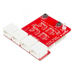
We have developed this Arduino Shield to connect your favorite Vernier sensors to any Arduino Uno or Arduino Uno compatible device.
What you'll need:
- Vernier Interface Shield
- Arduino Uno or Arduino Uno compatible board.
- Arduino software installed on your machine.
- A few Vernier sensors to play around with.
Suggested Reading
About Vernier
Vernier Software and Technology has been a leader in data collection and analysis for educators world-wide. Started in 1981 by David and Christine Vernier, they were amongst the first companies to design and promote the use of computers, sensors, and data collection in K-12 classroom laboratory experiments.
They currently have over 70 fully calibrated sensors and 5 different data collection interfaces that are part of their catalog. We have been very fortunate to partner and collaborate with Vernier in the development of this Arduino shield. It allows teachers to combine the power and versatility of the Arduino platform with the wealth of calibrated, classroom tested, and rugged sensors produced and supported by Vernier.
Vernier Shield Pin-out and Configuration
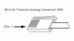
Vernier standardized all of their sensors using a "standard" British Telecom connector. These connectors each have 6 wires that connect the sensor to the Vernier data collection interface. We designed the shield to maximize flexibility and ease-of-use for integrating up to two analog (BTA) and two digital (BTD) Vernier sensors to an Arduino. The full sensor pin-outs can be found on Vernier's site here.
British Telecom Analog (BTA) – Right Hand
A large number of sensors used in the classroom fall under the category of "analog" sensors. Learn more about the differences between analog and digital here.
The pins of the BTA connector are defined as such:
| PIN # | Pin Name | Description
| 1
| Analog Sensor Output | (-10V to +10V) Used with a number of Vernier voltage probes. This is wired through a scale and shifting op-amp circuit so that the Arduino can read it on a scale of 0 - 5V.
| 2
| GND
| Ground.
| 3
| Vres
| Resistance reference. 15K pull-up resistor ties this pin to 5V to use as a voltage divider between Pin 6 and GND.
| 4*
| AutoIDENT
| Most sensors have a unique resistor that is tied between this pin and GND. Vernier uses this to identify the sensor. (not supported on all sensors)
| 5
| Power
| 5 VDC
| 6
| Analog Sensor Output | (0V to -5V) Primary sensor output for most analog sensors including light, temperature, force, pressure, pH, etc...
| |
http://www.vernier.com/support/sensor-pinouts/
To extend the use of Vernier equipment, they also offer a few voltage probes that allow for direct voltage measurements between +/- 6V, +/- 10V, and +/- 30V. On each of these probes, the signals are each tied to Pin 1 and and GND of the BTA connector.
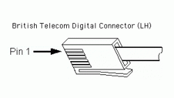
British Telecom Digital (BTD) – Left Hand
Digital sensors are any of the devices that return a signal that is either on (5V) or off (0V). Common digital sensors include: motion detector, photogate, radiation monitor, and the rotary motion sensors.
These sensors each have a somewhat unique pin-out definition. The following table outlines the pin assignments used for the Vernier digital connector.
Note that the connector is slightly different compared to the analog sensors. This is called a left-handed British Telecom connector and has the tab on the opposite side. The BTA and BTD connectors will not plug into the same socket.
| PIN # | DEFAULT | MOTION DETECTOR | PHOTOGATE | RADIATION MONITOR | ROTARY MOTION |
| 1 | IO1 | Echo | Input | Count | CCWcount |
| 2 | IO2 | Init | CWcount | ||
| 3 | IO3 | AutoIDENT | AutoIDENT | AutoIDENT | AutoIDENT |
| 4 | PWR | PWR | PWR | PWR | PWR |
| 5 | GND | GND | GND | GND | GND |
| 6 | IO4 | X4res |
Arduino Shield Pin Assignments
To maximize the flexibility of using all of the Vernier sensors, we have made the following pin assignments on our shield. Many of the Vernier sensors use I2C for identification and calibration data. We use a multiplexer to "share" (multiplex) pins A4 and A5 between all four connectors. The multiplexer is controlled with Pins 10 (LSB) and Pin 11 (MSB). See the section on multiplexing for more information.
Pin assignments for analog ports
| Analog 1 | Analog 2 | Description | |
| MUX Control Address | 00 | 01 | Pins 10 (LSB) and 11 (MSB) control a multiplexer for A4 and A5. |
| Analog Signal (O - 5V) | A0 | A2 | Most analog sensors will interface to this pin. Use A0 for Analog 1 and A2 for Analog 2. |
| Analog Signal (-10V - +10V) | A1 | A3 | The shield has a built-in circuit to scale and shift input voltages from -10V to +10V to a range of 0V to 5V for pins A1 and A3. |
| V_res | A4* | A4* | Resistance reference. 15K pull-up resistor ties this pin to 5V to use as a voltage divider between Pin 6 and GND. |
| AutoIDEN | A5* | A5* | A 10K pull-up resistor ties these pins to 5V. The measured voltage drop across this pin uniquely identifies the sensor. |
Pin assignments for digital ports
| Digital 1 | Digital 2 | Description | |
| MUX Control Address | 10 | 11 | Pins 10 (LSB) and 11 (MSB) control a multiplexer for A4 and A5. |
| IO1 (BTD Pin 1) | 2 | 6 | Signal pin used for the photogate, motion detector echo, radiation count, and CCW rotary motion count. |
| IO2 (BTD Pin 2) | 3 / A4* | 7 / A4* | Trigger pin for the motion detector and I2C data (SDA) for sensor ID |
| IO3 (BTD Pin 3) | 4 / A5* | 8 / A5* | I2C clock (SCL) for sensor ID |
| IO4 (BTD Pin 6) | 5 | 9 | Used for rotary motion sensor to increase sensitivity. |
*Pins A4 and A5 are shared across all four connectors. In order to properly access the BTA and BTD connector pins, you will need to interface the analog multiplexer circuit.
Auxillary Pins and Connections
In addition to the internal wiring and routing for the Vernier BTA and BTD connectors, we placed an indicator LED tied to pin 13, a general purpose button on pin 12, and a reset button on the shield.
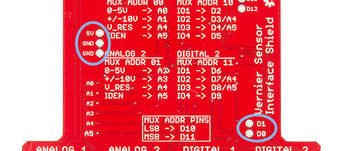
We also exposed vias for power and ground and pins 0 (RX) and 1 (TX) for adding serial communication peripherals like a Serial-enabled LCD or Serial 7-segment Display.
Multiplexer
Vernier uses a variety of methods for identifying which sensors are connected to the interface. A majority of sensors use a resistor placed on one of the pins, but some of their sensors use I2C for both sensor identification and storing calibration data. The Vernier shield uses an analog multiplexer to share / route pins A4 (SDA) and A5 (SCL) to each of the four connectors.
Pins 10 (LSB) and 11 (MSB) are used to control the multiplexer. The following snippet of code illustrates one way to switch which connector A4 and A5 are connected to.
language:c
const int muxLSB = 10;
const int muxMSB = 11;

void setup()
{
  pinMode(muxLSB, OUTPUT);
  pinMode(muxMSB, OUTPUT);
}
void setMux(int connectorNum)
{
// void setMux(int connectorNum)
// connectorNum is a number from 0 to 3 which
// identifies which connector to switch the MUX to.
// Where if connector num is equal to:
//    0 --> Analog 1
//    1 --> Analog 2
//    2 --> Digital 1
//    3 --> Digital 2

  switch (connectorNum)
  {
  case 1: // ANALOG 2 - MUX ADDR 01
    digitalWrite(muxMSB, LOW);
    digitalWrite(muxLSB, HIGH);
    break;
  case 2: // DIGITAL 1 - MUX ADDR 10
    digitalWrite(muxMSB, HIGH);
    digitalWrite(muxLSB, LOW);
    break;
  case 3: // DIGITAL 2 - MUX ADDR 11
    digitalWrite(muxMSB, HIGH);
    digitalWrite(muxLSB, HIGH);
    break;
  default: // ANALOG 1 - MUX ADDR 00
    digitalWrite(muxMSB, LOW);
    digitalWrite(muxLSB, LOW);
  }
}
In general, you won't need to access these lines unless you are interfacing to the Vernier sensors through I2C.
Vernier Sensor Identification
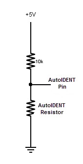
Vernier developed a very clever method to identify sensors connected to their interface using a simple, passive resistor. Many Vernier sensors can be uniquely identified by a specific resistor placed between the AutoIDENT pin and GND.
We have integrated a 10k Ohm pull-up resistor on the shield so that we can directly measure the AutoIDENT resistor using a simple voltage divider calculation.
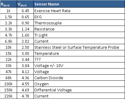
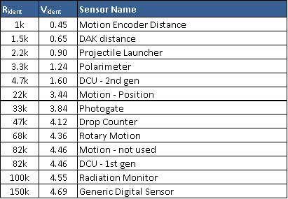
Nominal Resistor and voltage values for Vernier sensors
We've collected a list of popular sensors used by Vernier and their corresponding unique IDENT resistor values. These are nominal values and may vary within +/- 5%.
Analog Sensors
Digital Sensors
You will notice that there are not 70 sensors listed here. For all new sensors, Vernier has standardized on an I2C interface to query and communicate SensorID and calibration data. An example of this code is explained in the next section.
Example 1 - AutoID Arduino
The team at Vernier have helped us with creating a couple simple Arduino sketches that automatically query either the Analog or the Digital ports of the Arduino and report back the sensor identification and standard calibration data.
Vernier has created a wealth of examples hosted on github. Upload these sketches to your arduino device, and open up a Serial Monitor to view the data coming back to your computer.
AutoID Analog Sensors
This sketch is designed to automatically query the sensors connected to the two analog ports on the Vernier shield. After the AutoID, it prints the sensor information to the Serial Monitor and starts logging (calibrated) data to the screen. Written into this script are the default calibration constants used with Vernier's sensors.
This will, most likely, be the only Arduino sketch you need for most of your sensors.
As it is written, the data is collected once per second. Change the value of the variable TimeBetweenReadings to change the rate of the data collection.
Upload the VernierAnalogAutoID sketch to your Arduino.
language:c
    /*
VernierAnalogAutoID (v 2013.12)
Reads the information to AutoID a Vernier BTA sensor with digital AutoID,
and resistor ID sensors including Vernier Stainless Steel Temperature Probe (TMP-BTA).
It should read the +/-10 volt Voltage Probe correctly also.
This version does all tests for resistorID sensors first, then
turns on the I2C clock and tests for digital autoID sensors.)

Note that this sketch handles multiple pages of sensor calibrations.

When used with the SparkFun Vernier Interface Shield, this program will AutoID
two different sensors on BTA1 and BTA2. With homemade, breadboard
connections, it will work with only one sensor.

After the AutoID:
Assuming Vernier analog (BTA) Sensors are connected to the BTA connectors,
this sketch displays the time and sensor readings on the Serial Monitor.
As written, the readings will be displayed every second.
Change the variable TimeBetweenReadings to change the rate.
 See www.vernier.com/arduino for more information.
*/

//#define PLX_DAQ         // uncomment this line if using PLX_DAQ for data collection.
#include <Wire.h>
#include "vernierShield.h"


unsigned int BAUD_RATE = 9600;  // set data rate for Serial monitor to be the fastest possible.

int dataRate = 60;        // set # of samples per second.
int duration = 15000;      // set the data collection duration in milliseconds
                          // default value is set to 5 seconds or 5000 milliseconds
char delimiter = '\t';

// Variables used in the code for calculations
unsigned long timeRef;    // reference for starting time
unsigned long timeInterval;

unsigned long ReadingNumber; // index for data counter


void setup()
{
  pinMode(ledPin, OUTPUT);
  pinMode(buttonPin, INPUT_PULLUP);
  pinMode(muxlsb, OUTPUT);  // multiplexer pins for AutoID
  pinMode(muxmsb, OUTPUT);  // multiplexer pins for AutoID

  timeInterval = 1000 / dataRate;

#ifdef PLX_DAQ
  {
    delimiter = ',';
    BAUD_RATE = 56000;  // max speed for PLX_DAQ that matches with Arduino's data rates
  }
#endif
  Serial.begin(BAUD_RATE);
  digitalWrite(ledPin, LOW);

  device = 0x50;     // I2C Address for sensors - used for calibration data
  Serial.println("");

  // Read BTA1 Sensor
  digitalWrite(muxlsb, LOW); //set multiplexer for BTA1
  digitalWrite(muxmsb, LOW);
  BTAResistorSensorID(0);

  // Read BTA2 Sensor
  digitalWrite(muxlsb, HIGH); //set multiplexer for BTA2
  digitalWrite(muxmsb, LOW);
  BTAResistorSensorID(1);

  Wire.begin(); //start I2C communication

  // Read BTA1 Sensor
  digitalWrite(muxlsb, LOW); //set multiplexer for BTA1
  digitalWrite(muxmsb, LOW);
  if (SensorNumber[0] == 0) DigitalSensorID(0); // if no resistorID, check for digital ID

  // Read BTA2 Sensor
  digitalWrite(muxlsb, HIGH); //set multiplexer for BTA2
  digitalWrite(muxmsb, LOW);
  if (SensorNumber[1] == 0) DigitalSensorID(1); // if no resistorID, check for digital ID


  PrintSensorInfo(0);// this line can be commented out if you do not need all this info!!!
  PrintSensorInfo(1);// this line can be commented out if you do not need all this info

  PrintHeaderInfo();
  ReadingNumber = 0;
  timeRef = millis();

}

void loop()
{
  int Count[2]; //reading from 0 to 5 volt input
  int AltCount[2] ;//reading from -10 to +10V input
  float Voltage[2];
  float SensorReading[2];
  unsigned long currTime;

  currTime = millis();
  if ((currTime - timeRef) <= (duration))     // controls the duration of the data collection
  {
    if (currTime >= ReadingNumber * timeInterval + timeRef) // controls so only runs once per timeInterval
    {
      digitalWrite(ledPin, HIGH); //turn on LED
#ifdef PLX_DAQ
      {
        Serial.print("DATA,");
      }
#endif

      Serial.print((currTime - timeRef) / 1000.0, 3);
      for (int Channel = 0; Channel <= 1; Channel++)
      {
        Serial.print(delimiter); //tab character
        if (Name[Channel] == "Voltage +/- 10V")
        {
          AltCount[0] = analogRead(A1); //read both +/- 110 volt lines
          AltCount[1] = analogRead(A3);
          // convert from count to raw voltage if using 10 volt range:
          Voltage[Channel] = AltCount[Channel] / 1023.0 * 5.0 ;
        }
        else
        {
          Count[0] = analogRead(A0); //read both analog lines
          Count[1] = analogRead(A2);
          // convert from count to raw voltage on 0 to 5 range:
          Voltage[Channel] = Count[Channel] / 1023.0 * 5.0;
        }
        SensorReading[Channel] = Intercept[Channel] + Voltage[Channel] * Slope[Channel];
        //special calibration for thermistor temperture probe:
        if (SensorNumber[Channel] == 10) SensorReading[Channel] = Thermistor(Count[Channel]);
        Serial.print(SensorReading[Channel], 3);
      } // end of going through the channels

      Serial.println(" ");
      digitalWrite(ledPin, LOW);// LED on D13 flashes once per readng
      ReadingNumber++;
    }
  }
  else
  {
    digitalWrite(ledPin, LOW);

    PrintHeaderInfo();
    // reset counters and timeRef
    digitalWrite(ledPin, HIGH);
    ReadingNumber = 0;
    timeRef = millis();
  }
} // end

void BTAResistorSensorID(int Channel)
{
  Name[Channel] = ""; // clear name string
  ShortName[Channel] = ""; // clear name string
  SensorNumber[Channel] = 0;
  delay (10);
  int CountID = analogRead(A5);
  VoltageID[Channel] = CountID / 1023.0 * VCC;// convert from count to voltage
  if (VoltageID[Channel] > 0.86 & VoltageID[Channel] < 0.95) SensorNumber[Channel] = 1;
  if (VoltageID[Channel] > 3.80 & VoltageID[Channel] < 3.88) SensorNumber[Channel] = 2; // Voltage +/-10 V
  if (VoltageID[Channel] > 1.92 & VoltageID[Channel] < 2.13) SensorNumber[Channel] = 3;
  if (VoltageID[Channel] > 1.18 & VoltageID[Channel] < 1.30) SensorNumber[Channel] = 4;
  if (VoltageID[Channel] > 3.27 & VoltageID[Channel] < 3.68) SensorNumber[Channel] = 5;
  if (VoltageID[Channel] > 4.64 & VoltageID[Channel] < 4.73) SensorNumber[Channel] = 8; //Differential Voltage
  if (VoltageID[Channel] > 4.73 & VoltageID[Channel] < 4.83) SensorNumber[Channel] = 9; //Current
  if (VoltageID[Channel] > 2.38 & VoltageID[Channel] < 2.63) SensorNumber[Channel] = 10; //Stainless Steel or Surface Temperature Probe
  if (VoltageID[Channel] > 2.85 & VoltageID[Channel] < 3.15) SensorNumber[Channel] = 11;
  if (VoltageID[Channel] > 1.52 & VoltageID[Channel] < 1.68) SensorNumber[Channel] = 12; //TILT
  if (VoltageID[Channel] > 0.43 & VoltageID[Channel] < 0.48) SensorNumber[Channel] = 13;
  if (VoltageID[Channel] > 4.08 & VoltageID[Channel] < 4.16) SensorNumber[Channel] = 14;
  if (VoltageID[Channel] > 0.62 & VoltageID[Channel] < 0.68) SensorNumber[Channel] = 15;
  if (VoltageID[Channel] > 4.32 & VoltageID[Channel] < 4.40) SensorNumber[Channel] = 17;
  if (VoltageID[Channel] > 4.50 & VoltageID[Channel] < 4.59) SensorNumber[Channel] = 18; //Oxygen

  switch (SensorNumber[Channel])
  {
    case 1:
      Name[Channel] = "Thermocouple" ;
      Units[Channel] = "Deg C " ;
      ShortName[Channel] = "TC";
      Slope[Channel] = -2.45455;
      Intercept[Channel] = 6.2115;
      Page[Channel] = 1;; //calibration storage p (1,2, or 3)
      CalEquationType[Channel] = 1;
      break;
    case 2:
      Name[Channel] = "Voltage +/- 10V" ;  //!!! do not change this name or you will mess up the code of the loop
      Units[Channel] = "V" ;
      ShortName[Channel] = "Voltage10";
      Slope[Channel] = 4; //note correction for Sparkfun circuit done in calculation of Voltage!!
      Intercept[Channel] = -10;
      Page[Channel] = 1;; //calibration storage page
      CalEquationType[Channel] = 1;
      break;
    case 3:
      Name[Channel] = "Current" ;
      Units[Channel] = "Amps" ;
      ShortName[Channel] = "Current";
      Slope[Channel] = -2.665;
      Intercept[Channel] = 6.325;
      Page[Channel] = 1;; //calibration storage page
      CalEquationType[Channel] = 1;
      break;
    case 4:
      Name[Channel] = "Resistance" ;
      Units[Channel] = "Ohms" ;
      ShortName[Channel] = "Diff V";
      Slope[Channel] = -2.5;
      Intercept[Channel] = 6.25;
      Page[Channel] = 1;; //calibration storage page
      CalEquationType[Channel] = 1;
      break;
    case 8:
      Name[Channel] = "Diff Voltage" ;
      Units[Channel] = "V" ;
      ShortName[Channel] = "Diff V";
      Slope[Channel] = -2.5;
      Intercept[Channel] = 6.25;
      Page[Channel] = 1;; //calibration storage page
      CalEquationType[Channel] = 1;
      break;
    case 9:
      Name[Channel] = "Current" ;
      Units[Channel] = "Amp" ;
      ShortName[Channel] = "I";
      Slope[Channel] = 1;
      Intercept[Channel] = 0;
      Page[Channel] = 1;; //calibration storage page
      CalEquationType[Channel] = 1;
      break;
    case 10:
      Name[Channel] = "Temperature" ;
      Units[Channel] = "Deg C" ;
      ShortName[Channel] = "Temp";
      Slope[Channel] = 1;
      Intercept[Channel] = 0;
      Page[Channel] = 1;; //calibration storage page
      CalEquationType[Channel] = 1;
      break;
    case 11:
      Name[Channel] = "Temperature" ;
      Units[Channel] = "Deg C" ;
      ShortName[Channel] = "Temp";
      Slope[Channel] = 1;
      Intercept[Channel] = 0;
      Page[Channel] = 1;; //calibration storage page
      CalEquationType[Channel] = 1;
      break;
    case 12:
      Name[Channel] = "TI Light" ;
      Units[Channel] = "relative" ;
      ShortName[Channel] = "TI Light";
      Slope[Channel] = 1;
      Intercept[Channel] = 0;
      Page[Channel] = 1;; //calibration storage page
      CalEquationType[Channel] = 1;
      break;
    case 13:
      Name[Channel] = "Exercise Heart Rate" ;
      Units[Channel] = "V" ;
      ShortName[Channel] = "Ex HR";
      Slope[Channel] = 1;
      Intercept[Channel] = 0;
      Page[Channel] = 1;; //calibration storage page
      CalEquationType[Channel] = 1;
      break;
    case 14:
      Name[Channel] = "Voltage" ;
      Units[Channel] = "V" ;
      ShortName[Channel] = "Volts";
      Slope[Channel] = 1;
      Intercept[Channel] = 0;
      Page[Channel] = 1;; //calibration storage page
      CalEquationType[Channel] = 1;
      break;
    case 15:
      Name[Channel] = "EKG" ;
      Units[Channel] = "V" ;
      ShortName[Channel] = "EKG";
      Slope[Channel] = 1;
      Intercept[Channel] = 0;
      Page[Channel] = 1;; //calibration storage page
      CalEquationType[Channel] = 1;
      break;
    case 17:
      Name[Channel] = "Carbon Dioxide" ;
      Units[Channel] = "ppm" ;
      ShortName[Channel] = "CO2";
      Slope[Channel] = 1;
      Intercept[Channel] = 0;
      Page[Channel] = 1;; //calibration storage page
      CalEquationType[Channel] = 1;
      break;
    case 18:
      Name[Channel] = "Oxygen" ;
      Units[Channel] = "%" ;
      ShortName[Channel] = "O2";
      Slope[Channel] = 1;
      Intercept[Channel] = 0;
      Page[Channel] = 1;; //calibration storage page
      CalEquationType[Channel] = 1;
      break;
    default:
      Name[Channel] = "nothing on BTA" ;
      SensorNumber[Channel] = 0; //
      Units[Channel] = "" ;
      ShortName[Channel] = "";
      Slope[Channel] = 1;
      Intercept[Channel] = 0;
      Page[Channel] = 1;; //calibration storage page
      CalEquationType[Channel] = 1;
      break;
  } // end of switch case
} //end of BTA resistor check

void DigitalSensorID(int Channel)
{
  int i;
  int x;
  // check for digital ID sensor:
  for (i = 0; i < 128; i++) // clear our digital ID sensor data
  {
    sensordata[i] = 0;
  }
  //Now check for Digital AutoID sensor:
  Wire.begin(); // join i2c bus (address optional for master) !!!
  //Reading device first time... ;
  Wire.beginTransmission(device);  // Now we're going to read it back
  Wire.write(0x0);                 // Sending address 0, so it knows where we'll want
  Wire.endTransmission();          // to read from
  x = Wire.requestFrom(device, 32); // Start new transmission and keep reading for 128 bytes
  i = 1;
  Serial.print("Wire Request In: ");
  Serial.println(x);
  while (x > 1)
  {
    x = Wire.available();
    char c = Wire.read();    // Read a byte and write it out to the Serial port
    sensordata [i] = c;
    i++;
  }
  //Reading device second time... ;
  Wire.beginTransmission(device); // Now we're going to read it back
  Wire.write(0x20);               // Sending address 0, so it knows where we'll want
  Wire.endTransmission();       // to read from
  x = Wire.requestFrom(device, 32);  // Start new transmission and keep reading for 128 bytes
  i = 1;
  while (x > 1)
  {
    x = Wire.available();
    char c = Wire.read();    // Read a byte and write it out to the Serial port
    sensordata [i + 32] = c;
    i++;
  }
  //Reading device third time... ;
  Wire.beginTransmission(device); // Now we're going to read it back
  Wire.write(0x40);               // Sending address 0, so it knows where we'll want
  Wire.endTransmission();         // to read from
  x = Wire.requestFrom(device, 32); // Start new transmission and keep reading for 128 bytes
  i = 1;
  while (x > 1)
  {
    x = Wire.available();
    char c = Wire.read();    // Read a byte and write it out to the Serial port
    sensordata [i + 64] = c;
    i++;
  }
  //Reading device a forth time... ;
  Wire.beginTransmission(device); // Now we're going to read it back
  Wire.write(0x60);               // Sending address 0, so it knows where we'll want
  Wire.endTransmission();       // to read from
  x = Wire.requestFrom(device, 32);  // Start new transmission and keep reading for 128 bytes
  i = 1;
  while (x > 1)
  {
    x = Wire.available();
    char c = Wire.read();    // Read a byte and write it out to the Serial port
    sensordata [i + 96] = c;
    i++;
  }
  //      Print out array:  // remove *'s to get this display for diagnostics

#ifdef DEBUG

  Serial.println("array: ");
  for (i = 1; i <= 128; i++)
  {
    Serial.print (i);
    Serial.print ("\t ");
    Serial.print(sensordata[i], DEC);
    Serial.print ("\t ");
    Serial.println(char(sensordata[i]));
  }
#endif

  //******************************************************************
  //Determine sensor number:
  //  VoltageID[Channel]=-1;// indicated resistor ID not used
  SensorNumber[Channel] = sensordata[2];

  //Determine the sensor name:
  Name[Channel] = "";
  for (i = 0; i < 20; i++)
  {
    char c =  sensordata[i + 9]; // 9 byte offset
    Name[Channel] += c;
  }
  Name[Channel] += '\0';    //add terminating character

  //Determine the short name:
  ShortName[Channel] = "";
  for (i = 0; i < 12; i++)
  {
    char c =  sensordata[i + 29]; // 29 byte offset
    ShortName[Channel] += c;
  }
  ShortName[Channel] += '\0';    //add terminating character

  //Determine the calibration equation type:
  CalEquationType[Channel] = sensordata[57];

  //Determines the  calibration page:
  Page[Channel] = sensordata[70];

  // the code below uses the calibration page set:
  // Intercept starts at 71 for page 1, 90 for p2, and 109 for p3

  //Determines intercept:
  for (i = 0; i < 4; i++)
  {
    floatbyte[i] = sensordata[i + 71 + (Page[Channel]) * 19];
  }
  float j = *(float*) &floatbyte;
  Intercept[Channel] = j;

  //Determines slope:
  // slope starts at 75 for page 1, 94 for p2, and 113 for p3
  for (i = 0; i < 4; i++)
  {
    floatbyte[i] = sensordata[i + 75 + (Page[Channel]) * 19];
  }
  float y = *(float*) &floatbyte;
  Slope[Channel] = y;

  //Determines the units:
  // the cryptic code in the next line just uses the
  // correct bytes, depending on the page selected.
  // units start at 83 for page 1, 102 for p2, and 121 for p3
  for (i = 0; i < 7; i++)
  {
    char c =  sensordata[83 + i + (Page[Channel]) * 19];
    Units[Channel] += c;
  }
  Units[Channel] += '\0';    //add terminating character
} //end of checking for digital ID sensor

void PrintHeaderInfo()
{
  Serial.println();
  Serial.println("**************************************************");
  Serial.println("*   Push the D12 button to start collection.     *");
  Serial.println("*      Use reset button to reset / stop          *");
  Serial.println("**************************************************");
  while (digitalRead(buttonPin) == HIGH)
  {
    // holding loop until the button goes low.
  }
  Serial.println("Vernier Format 2");
  Serial.println("Sensor Readings taken using Ardunio");
  Serial.println("Data Set");

#ifdef PLX_DAQ
  {
    Serial.println("CLEARDATA");
    Serial.print("LABEL,");
  }
#endif

  Serial.print("Time");
  for (int chan = 0; chan <= 1; chan++)
  {
    Serial.print(delimiter); //tab character
    //print sensor name:
    Serial.print (ShortName[chan]);
  }
  Serial.println("");

  Serial.print("seconds");

  for (int chan = 0; chan <= 1; chan++)
  {
    Serial.print("\t"); //tab character
    //print sensor name:
    Serial.print (Units[chan]);
  }
  Serial.println ("");
}


void PrintSensorInfo(int Channel)
{ // print out information about sensor:
  //(This code is commented out, but add it for more feedback)
  Serial.println(" ");
  Serial.print("BTA Connector ");
  Serial.println(Channel);
  Serial.print("sensor ID number: ");
  Serial.println(SensorNumber[Channel]);
  Serial.print("ID voltage level: ");
  Serial.println(VoltageID[Channel]);
  Serial.print("sensor name: ");
  Serial.println (Name[Channel]);
  Serial.print("sensor short name: ");
  Serial.println (ShortName[Channel]);
  Serial.print("calibration page: ");
  Serial.println(Page[Channel]);
  Serial.print("calibration equation type: ");
  Serial.println(CalEquationType[Channel]);
  Serial.print("intercept: ");
  Serial.println (Intercept[Channel]);
  Serial.print("slope ");
  Serial. println(Slope[Channel]);
  Serial.print("units: ");
  Serial.println (Units[Channel]);
}// end of PrintSensorInfo

float Thermistor(int Raw) //This function calculates temperature from ADC count
{
  /* Inputs ADC count from Thermistor and outputs Temperature in Celsius
  *  requires: include <math.h>
  * There is a huge amount of information on the web about using thermistors with the Arduino.
  * Here we are concerned about using the Vernier Stainless Steel Temperature Probe TMP-BTA and the
  * Vernier Surface Temperature Probe STS-BTA, but the general principles are easy to extend to other
  * thermistors.
  * This version utilizes the Steinhart-Hart Thermistor Equation:
  *    Temperature in Kelvin = 1 / {A + B[ln(R)] + C[ln(R)]3}
  *   for the themistor in the Vernier TMP-BTA probe:
  *    A =0.00102119 , B = 0.000222468 and C = 1.33342E-7
  *    Using these values should get agreement within 1 degree C to the same probe used with one
  *    of the Vernier interfaces
  *
  * Schematic:
  *   [Ground] -- [thermistor] -------- | -- [15,000 ohm bridge resistor] --[Vcc (5v)]
  *                                     |
  *                                Analog Pin 0
  *

  For the circuit above:
  * Resistance = ( Count*RawADC /(1024-Count))
   */
  long Resistance;
  float Resistor = 15000; //bridge resistor
  // the measured resistance of your particular bridge resistor in
  //the Vernier BTA-ELV this is a precision 15K resisitor
  float Temp;  // Dual-Purpose variable to save space.
  Resistance = ( Resistor * Raw / (1024 - Raw));
  Temp = log(Resistance); // Saving the Log(resistance) so not to calculate  it 4 times later
  Temp = 1 / (0.00102119 + (0.000222468 * Temp) + (0.000000133342 * Temp * Temp * Temp));
  Temp = Temp - 273.15;  // Convert Kelvin to Celsius
  return Temp;                                      // Return the Temperature
}
Once your code is uploaded, open the serial terminal in the IDE and see the output.
AutoID Digital Sensors
This sketch queries the digital sensors connected to the Vernier Shield and prints out the information to the Serial Monitor. Because each digital sensor is unique, this sketch does not start logging data or printing out results. It will, however, suggest the name of the Vernier Arduino sketch to use. You can find these on the Vernier github repository.
Upload the VernierDigitalAutoID sketch to your Arduino.
language:c
    /*
VernierDigitalAutoID (v 2013.12)
Reads the information to AutoID a Vernier BTD sensor with resistor ID.

When used with the SparkFun Vernier Interface Shield, this program will AutoID
two different sensors on BTD1 and BTD2. With homemade, breadboard
connections, it will work with only one sensor.

After the AutoID, assuming Vernier analog (BTD) Sensors are connected to the BTD connectors,
this sketch displays the name of the sensor and the units. This sketch does not read data
because there are several different types of readings that can be done with digital sensors
(distance measurements, radiation counts, photogate timing, etc). Instead, this sketch
will name the Vernier Arduino sketch to use to read that sensor. For example, if you connect
a Motion Detector, it will suggest the VernierMotionDetector program.

 See www.vernier.com/arduino for more information.
*/
int ReadingNumber;
int Channel; //BTA (Channel 1 or 2) or BTD connector (Channel 3 or 4)
float VoltageID[5];
int led =13;
int SensorNumber[5]; //integer indicating sensor number'
String Name[5];
String ShortName[5];
String Units[5];
float Intercept[5];
float Slope[5];
int Page[5];
int (CalEquationType[5]);
float VCC= 5.00;// "5 volt" power supply voltage used in resistor ID section
void setup()
 {
    int muxlsb = 10; //low byte of multiplexer
    int muxmsb = 11; //high byte of multiplexer
    Serial.begin(9600);
    pinMode(led, OUTPUT); //LED on SparkFun Vernier Shield
    digitalWrite(led, LOW);
    pinMode(muxlsb, OUTPUT);
    pinMode(muxmsb, OUTPUT);
    Serial.println("");
    //Read BTD1 Sensor:
    digitalWrite(muxlsb, LOW); //set multiplexer for BTD1
    digitalWrite(muxmsb, HIGH);
    Channel=3;
    BTDResistorSensorID(Channel);
    PrintSensorInfo();// this line can be commented out if you do not need all this info !!!
    //Read BTD2 Sensor
    digitalWrite(muxlsb, HIGH); //set multiplexer for BTD2
    digitalWrite(muxmsb, HIGH);
    Channel=4;
    BTDResistorSensorID(Channel);
    PrintSensorInfo();// this line can be commented out if you do not need all this info !!!
  }

void loop()
  {
  }

void BTDResistorSensorID(int Channel)
   {
      Name[Channel]="";// clear name string
      ShortName[Channel]="";// clear name string
      SensorNumber[Channel] = 0;
      delay (10);
      int CountID = analogRead(A5);
      VoltageID[Channel] = CountID / 1024.0 * VCC;// convert from count to voltage
      if (VoltageID[Channel]>3.27 & VoltageID[Channel]<3.61) SensorNumber[Channel] = 2; //Motion Detector
      if (VoltageID[Channel]>4.45 & VoltageID[Channel]<4.46) SensorNumber[Channel] = 3; //motion not used
      if (VoltageID[Channel]>3.80 & VoltageID[Channel]<3.88) SensorNumber[Channel] = 4;  //photogate
      if (VoltageID[Channel]>4.08 & VoltageID[Channel]<4.16) SensorNumber[Channel] = 5; //Drop Counter
      if (VoltageID[Channel]>4.32 & VoltageID[Channel]<4.40) SensorNumber[Channel] = 6; //rotary
      if (VoltageID[Channel]>4.50 & VoltageID[Channel]<4.59) SensorNumber[Channel] = 7;//Radiation Monitor
      if (VoltageID[Channel]>4.45 & VoltageID[Channel]<4.46) SensorNumber[Channel] = 8; //DCU - 1st generation
      if (VoltageID[Channel]>1.52 & VoltageID[Channel]<1.68) SensorNumber[Channel] = 9; //DCU - 2nd generation
      if (VoltageID[Channel]>1.18 & VoltageID[Channel]<1.30) SensorNumber[Channel] = 10; //Polarimeter
      if (VoltageID[Channel]>0.86 & VoltageID[Channel]<0.95) SensorNumber[Channel] = 11;   //Projectile Launcher
      if (VoltageID[Channel]>0.62 & VoltageID[Channel]<0.68) SensorNumber[Channel] = 12; //Linear Translator for DAK
      if (VoltageID[Channel]>0.43 & VoltageID[Channel]<0.48) SensorNumber[Channel] = 13; //Motion Encoder
      if (VoltageID[Channel]>4.64 & VoltageID[Channel]<4.73) SensorNumber[Channel] = 14; // possible digital sensor
      switch (SensorNumber[Channel])
         {
            case 2:
                  Name[Channel] = "Motion - Position" ;
                  Units[Channel] = "Use VernierMotionDetector" ;
                  ShortName[Channel] = "Position";
                  Slope[Channel]=1;
                  Intercept[Channel]=0;
                  Page[Channel] = 1;; //calibration storage page
                  CalEquationType[Channel]=1;
            break;
            case 3:
                  Name[Channel] = "Motion -NU" ;
                  Units[Channel] = "not used" ;
                  ShortName[Channel] = "Motion -NU";
                  Slope[Channel]=1;
                  Intercept[Channel]=0;
                  Page[Channel] = 1;; //calibration storage page
                  CalEquationType[Channel]=1;
            break;
            case 4:
                  Name[Channel] = "Photogate" ;
                  Units[Channel] = "Use VernierPhotogate" ;
                  ShortName[Channel] = "PG";
                  Slope[Channel]=1;
                  Intercept[Channel]=0;
                  Page[Channel] = 1;; //calibration storage page
                  CalEquationType[Channel]=1;
            break;
            case 5:
                  Name[Channel] = "Drop Counter" ;
                  Units[Channel] = "Use VernierCount" ;
                  ShortName[Channel] = "Drop Count";
                  Slope[Channel]=1;
                  Intercept[Channel]=0;
                  Page[Channel] = 1;; //calibration storage page
                  CalEquationType[Channel]=1;
            break;
            case 6:
                  Name[Channel] = "Rotary Motion" ;
                  Units[Channel] = "Use VernierRotary" ;
                  ShortName[Channel] = "Rotary";
                  Slope[Channel]=1;
                  Intercept[Channel]=0;
                  Page[Channel] = 1;; //calibration storage page
                  CalEquationType[Channel]=1;
            break;
            case 7:
                  Name[Channel] = "Radiation Monitor" ;
                  Units[Channel] = "Use Count" ;
                  ShortName[Channel] = "VernierRadiation";
                  Slope[Channel]=1;
                  Intercept[Channel]=0;
                  Page[Channel] = 1;; //calibration storage page
                  CalEquationType[Channel]=1;
            break;
            case 8:
                  Name[Channel] = "DCU - 1st gen" ;
                  Units[Channel] = "Use VernierDCU" ;
                  ShortName[Channel] = "DCU -1";
                  Slope[Channel]=1;
                  Intercept[Channel]=0;
                  Page[Channel] = 1;; //calibration storage page
                  CalEquationType[Channel]=1;
            break;
            case 9:
                  Name[Channel] = "DCU - 2nd gen" ;
                  Units[Channel] = "Use VernierDCU" ;
                  ShortName[Channel] = "DCU-2";
                  Slope[Channel]=1;
                  Intercept[Channel]=0;
                  Page[Channel] = 1;; //calibration storage page
                  CalEquationType[Channel]=1;
            break;
            case 10:
                  Name[Channel] = "Polarimeter" ;
                  Units[Channel] = "-----" ;
                  ShortName[Channel] = "Polarimeter";
                  Slope[Channel]=1;
                  Intercept[Channel]=0;
                  Page[Channel] = 1;; //calibration storage page
                  CalEquationType[Channel]=1;
            break;
            case 11:
                  Name[Channel] = "Projectile Launcher" ;
                  Units[Channel] = "Use VernierPhotogate" ;
                  ShortName[Channel] = "Proj Time";
                  Slope[Channel]=1;
                  Intercept[Channel]=0;
                  Page[Channel] = 1;; //calibration storage page
                  CalEquationType[Channel]=1;
            break;
            case 12:
                  Name[Channel] = "DAK distance" ;
                  Units[Channel] = "Use VernierRotary" ;
                  ShortName[Channel] = "DAK d";
                  Slope[Channel]=1;
                  Intercept[Channel]=0;
                  Page[Channel] = 1;; //calibration storage page
                  CalEquationType[Channel]=1;
            break;
            case 13:
                  Name[Channel] = "Motion Encoder Dist" ;
                  Units[Channel] = "Use VernierRotary" ;
                  ShortName[Channel] = "ME Dist";
                  Slope[Channel]=1;
                  Intercept[Channel]=0;
                  Page[Channel] = 1;; //calibration storage page
                  CalEquationType[Channel]=1;
            break;
            case 14:
                  Name[Channel] = "Digital Sensor" ;
                  Units[Channel] = "read digital ID" ;
                  ShortName[Channel] = "D&";
                  Slope[Channel]=1;
                  Intercept[Channel]=0;
                  Page[Channel] = 1;; //calibration storage page
                  CalEquationType[Channel]=1;
             break;
             default:
                  Name[Channel] = "nothing on BTD" ;
                  SensorNumber[Channel] = 0; //
                  Units[Channel] = "" ;
                  ShortName[Channel] = "";
                  Slope[Channel]=1;
                  Intercept[Channel]=0;
                  Page[Channel] = 1;; //calibration storage page
                  CalEquationType[Channel]=1;
             break;
         } // end of switch case
    } // end of BTD resistor check


void PrintSensorInfo()
 {// print out information about sensor
   Serial.println(" ");
   Serial.print("BTD connector ");
   Serial.println(Channel-2);
   Serial.print("sensor ID number: ");
   Serial.println(SensorNumber[Channel]);
   Serial.print("ID voltage level: ");
   Serial.println(VoltageID[Channel]);
   Serial.print("sensor name: ");
   Serial.println (Name[Channel]);
   Serial.print("sensor short name: ");
   Serial.println (ShortName[Channel]);
   Serial.print("calibration page: ");
   Serial.println(Page[Channel]);
   Serial.print("calibration equation type: ");
   Serial.println(CalEquationType[Channel]);
   Serial.print("intercept: ");
   Serial.println (Intercept[Channel]);
   Serial.print("slope ");
   Serial. println(Slope[Channel]);
   Serial.print("Program to use: ");
   Serial.println (Units[Channel]);
   }// end of PrintSensorInfo
Example 2 - Photogate Timer
In many classrooms, a standard stopwatch or timer is used to measure the time elapsed for moving objects such as mousetrap car races, rolling dynamics carts, or falling tennis balls.
These little stopwatches are great for most simple activities, but for many investigations and experiments, human reaction time and classroom distractions often introduce too much error and uncertainty to collect repeatable results for students to draw clear conclusions from their data.
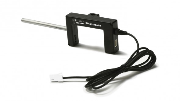
Integrating a photogate timer is one of the simplest and low-cost tools a teacher can use. A photogate is simply an infra-red LED and receiver pair. The photogate normally produces a HIGH signal on DIO0 when the gate is unblocked. When an object passes through the gate, the signal is LOW until the gate is unblocked again.
Integrating this with a very fast timer, we can achieve very reliable and precise timing results.
The Arduino UNO has a 16 MHz clock. Accounting for overhead events and extra needed clock cycles and such, the Arduino is capable of timing results with a precision better than +/- 1 uS.
This code example is interrupt driven and uses the micros() arduino command to return the number of microseconds since the start of the program. This number is stored in an unsigned long variable. This gives the program a maximum time limit of about 1 hour and 11 minutes before the counter wraps. Generally speaking, we're looking to capture the amount of time for a marble, toy car, or playing card to move through the gate.
This sketch simply outputs an event entry to the Serial Monitor with the Event #, the photogate state (Blocked or Unblocked), and the time since the start of the program.
language:c
    /*
 VernierPhotogateTimer (v 2013.12.09)
 Monitors a Vernier Photogate connected to BTD connector.

 This sketch lists the time in microseconds since the program started running.

 To ensure the greatest accuracy, this code is written using interrupts.
 For more information about using interrupts, see:
 http://playground.arduino.cc/Code/Interrupts

 For more details around using Arduino with Vernier see
 www.vernier.com/arduino.

 Modified by: B. Huang, SparkFun Electronics
 December 9, 2013

 This version incorporates a "circular" buffer of 150 elements and stores all events
 (blocking and unblocking) of the photogate to an precision of 1 us. In addition,
 the data is streamed to the Serial buffer and can be captured, copied, exported,
 and analyzed in your favorite analysis tool -- Graphical Analysis, LoggerPro, Excel,
 Google Sheets, Matlab, etc...

 */
#include <SoftwareSerial.h>

// mode variable definitions
#define GATE_MODE 1
#define PULSE_MODE 2
#define PENDULUM_MODE 3

#define bufferSize 150  // Sets the size of the circular buffer for storing interrupt data events. Increasing this may cause erratic behavior of the code.
#define DELIM '\t'   // this is the data delimitter. Default setting is a tab character ("\t")

const int baudRate = 9600;  // Baud rate for serial communications. Increase this for high data rate applications (i.e. smart pulley)

unsigned int refreshRate = 250;  // sets # of milliseconds between refreshes of LED Display

const int buttonPin = 12;   // default buttonPin on Vernier Shield
const int ledPin = 13;    // re-purposed pin 13 to tie to the Serial 7 Segment
const int photogatePin = 2; // default pin if plugged into Digital 1 on SparkFun Vernier Shield

/* The following variables are all used and modified by the code. These should not be changed or re-named. */
int mode = 1; // sets the default mode of operation
// Mode 1 -- Gate, Mode 2 -- Pulse, Mode 3 -- Pendulum

int lastState;
int currTimeDigits;
unsigned long currTime;
unsigned long timerOffset = 0;
unsigned int displayIndex; // the current item that has been displayed to the Serial Monitor from the data buffer.
unsigned int count;  // tracks the total # of data entries

char tempString[4];   // String buffer to store for sending to the serial 7 segment display

/* These variables are all accessed and modified by the interrupt handler "PhotogateEvent"
Variables used by the Interrupt handler must be defined as volatile. */
volatile int photogate = HIGH;
volatile int start = 0;  // 1 == start, 0 == stop
volatile unsigned int numBlocks;
volatile unsigned long startTime;  //Time in us
volatile unsigned long stopTime;  //Time in us
volatile byte dataIndex;
volatile byte displayCount;  // stores the number of items in data Buffer to be displayed
volatile byte state[bufferSize];
volatile unsigned long time_us[bufferSize]; // Time in us

void setup()
{
  attachInterrupt(0, photogateEvent, CHANGE); // photogate_event
  pinMode(buttonPin, INPUT_PULLUP);
  pinMode(ledPin, OUTPUT);
  Serial.begin(9600);           // set up Serial library at 9600 bps
  displayHeader();
};// end of setup

void loop ()
{
  // check for button press to change modes
  if (digitalRead(12) == LOW)
  {
    resetCount();

    while((digitalRead(buttonPin) == LOW)); // hold until button is released
    delay(10); // for de-bouncing
    displayHeader();
  } // if button is pressed

  if (displayCount > 0)  // only display to Serial monitor if an interrupt has added data to the data buffer.
  {
    count++;
    Serial.print(count);
    Serial.print(DELIM); //tab character
    Serial.print(state[displayIndex]);
    Serial.print(DELIM); //tab character
    Serial.print((time_us[displayIndex] - timerOffset) / 1E6, 6);  // at least 6 sig figs

    Serial.println();

    displayIndex++;
    if(displayIndex >= bufferSize)
    {
      displayIndex = 0;
    }
    displayCount--; // deduct one
  }
} // end of loop

void resetCount()
{
  dataIndex = 0;
  displayIndex = 0;
  count = 0;
  numBlocks = 0;
  start = 0;
  Serial.println();
  Serial.println("*****Reset*****");
  Serial.println();
  timerOffset = micros();

}

/*************************************************
 * photogateEvent()
 *
 * Interrupt service routine. Handles capturing
 * the time and saving this to memory when the
 * photogate issues an interrupt on pin 2.
 *
 * As it is currently written, the photogate
 * will only work on Digital Port 1.
 *************************************************/
void photogateEvent()
{
  time_us[dataIndex] = micros();

  photogate = digitalRead(photogatePin);

  if (photogate == 1)
  {
    state[dataIndex] = 0;  // reverses the result so that 1 = blocked, 0 = open
    digitalWrite(ledPin, LOW);  // turns the indicator LED off
  }
  else
  {
    state[dataIndex] = 1;                  // normal operation is 1 = open and 0 = blocked
    digitalWrite(ledPin, HIGH);   // turns the indicator LED on
  }
  displayCount++;  // add one to "to be displayed" buffer

  dataIndex++;
  if(dataIndex >= bufferSize)
  {
    dataIndex = 0;
  }
}

/*************************************************
 * displayHeader()
 *
 * Presents the data header to Serial Monitor
 * This data is tab delimitted and can be copied
 * and pasted directly into Excel or spreadsheet
 * / graphing program.
 *************************************************/
void displayHeader()
{
  Serial.println("Vernier Format 2");
  Serial.println();
  Serial.print("Event");
  Serial.print(DELIM);
  Serial.print("Blocked");
  Serial.print(DELIM);
  Serial.print("Time       ");
  Serial.println();

// Units
  Serial.print("#");
  Serial.print(DELIM);
  Serial.print("(n/a)");
  Serial.print(DELIM);
  Serial.print("(s)         ");
  Serial.println();


  Serial.println("--------------------------");
}
Data Output Format
The data is tab delimitted, and you can simply copy-paste this into your favorite data analysis program such as LoggerPro, Matlab, Google Sheets, or Excel.
Vernier Format 2

Event    Blocked    Time
#   (n/a)   (s)
--------------------------
1   1   1.885308
2   0   1.903900
3   1   1.908432
4   0   1.927056
5   1   1.945756
6   0   1.964332
7   1   1.980148
8   0   1.996724
Sensor Calibration and Verification - Falling Picket Fence
The Falling Picket Fence is a classic activity used in many physics classes. It extends and combines the concepts of average velocity to instantaneous velocity and explore uniform acceleration and the nature of the acceleration due to gravity.
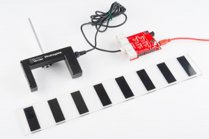
A picket fence is nothing more than a clear piece of plastic with opaque bars spaced 5 centimeters apart (center-to-center).
Dropping a picket fence near the surface of the Earth should accelerate uniformly at a rate of 9.8 m/s/s. I used this to verify and check the accuracy of the timing. I used the sample code from above and dropped a picket fence through the photogate, and here is the data it returned:
Vernier Format 2

Event   Blocked    Time
#   (n/a)   (s)
--------------------------
1   1   5.520980
2   0   5.542184
3   1   5.570784
4   0   5.584924
5   1   5.605876
6   0   5.617208
7   1   5.635028
8   0   5.644568
9   1   5.659904
10  0   5.668612
11  1   5.682448
12  0   5.690280
13  1   5.702860
14  0   5.710160
15  1   5.721872
16  0   5.728644
Clearly that's accelerating at 9.8 m/s/s, right?
Okay, you're right. It's about as clear as mud. It's just a bunch of numbers, but if you look closely, you can see that the time between events appears to be getting smaller and smaller. Ah, ha! It's speeding up! That's a good sign.
The raw data is difficult to understand without processing, so I created a sample worksheet that can be used in any class. The worksheet calculates the average velocity between blocking events.
Using the worksheet, I graphed velocity vs. time and found the slope.
|
Data Statistics slope: 9.78799 m/s/s intercept: 0.758978 m/s |
Is it right? Well - I try to avoid making right vs. wrong judgements in science. It is simply data, and all I can say is that it appears to agree with our existing assumptions and observations of the universe.
Other things you can do with photogates?
Check out the Vernier Photogate Timer Project tutorial.
Example 3 - Motion Detector
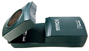
Vernier's motion detector sensor is one of the most popular sensors used in classrooms. It uses a ultrasonic transducer similar ones used in older auto-focusing Polaroid cameras.
Combined with a graphing utility, it allows students to immediately see how position varies with time and how the slope of this graph is related to quantities such as velocity and acceleration.
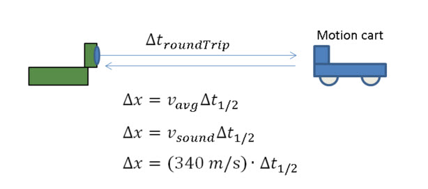
The motion detector uses echo-location or sonar to determine the distance of objects in front of the sensor. It works by emitting an ultrasonic pulse and then listening for the echo of the pulse from the reflection off objects. The Vernier motion detector uses two pins for this:
Init (Pin 2 on the BTD connector)
Echo (Pin 1 on the BTD connector)
On the Vernier shield, we have these pins tied to:
| Digital 1 | Digital 2 | ||
| INIT | 4 | 8 | Trigger pin to send the ultrasonic pulse. |
| ECHO | 3 | 7 | Listen to this pin for the echo return / reflection. |
Using the Arduino function micros, we can catch the time of the echo to an accuracy of 1 us. If we assume that sound travels at a speed of about 340 m/s, this translates to a round-trip accuracy of better than 1 mm.
Because we know that sound travels at a constant speed in a uniform medium, we can use simple kinematics to determine the distance the reflected sound travelled. In our code, we assume that the speed of sound is nominally 340 m/s. If you care to account for differences in temperature, hyperphysics has a great tool to calculate and adjust for differences in temperature.
Code example
The following code example has been adapted from the Vernier github repository. This sketch will record at a dataRate of 20 samples per second for a duration of 5 seconds. There are two variables declared in the beginning of the code that control these two parameters.
After uploading this file to your Arduino, open up a Serial Monitor and press the push button (D12) to start the data collection. Data will be displayed to the Serial Monitor. You can copy-paste this into Excel, Matlab, or LoggerPro for analysis. Or, you use a Serial graphing program like SerialChart, MakerPlot, or write your own in Processing.
language:c
    /*
 VernierMotionDetector.ino
===========================
 Modified from Vernier example code: VernierMotionDetector (v 2013.11)
 Takes data from a Vernier Motion Detector connected to BTD connector on
 SparkFun Vernier Interface Shield.

 This sketch measures the time taken for the ultrasound to return (in microseconds)
 and then calculates the corresponding distance (based on the speed of ultrasound
 in air) and displays the distance (in cm) on the Serial Monitor.

 The data is displayed to the serial monitor as a tab delimitted format. Change the
 delimiter variable to a comma ',' for Comma-Separated-Value (CSV) format.

 Here is how the Vernier Motion Detector works:
 - when the INIT pin (Arduino Pin 3 or 7) is pulled high, this triggers the
 ultrasound pulse
 - program then starts timing but then delays 0.882 ms (blanking time),
 0.882 ms is the time it takes ultrasound to travel 15 cm twice (round trip))
 assuming a speed of 340 m/s
 - the program then monitors ECHO pin (Arduino Pin 2 or 6), waiting for it to '
 go high. This happens when an echo is detected.

 Modifications by B. Huang (Feb 2014)
 -------------------------
 Removed the use of delays in the loop() function. Uses a timeRef variable
 Added a variable called dataRate. dataRate describes the # of samples per second.
 Added a variable called duration. duration sets the time duration for data collection

 See www.vernier.com/arduino for more information.
 */
#define speedOfSound 340 // speed of sound in m/s

int dataRate = 20;        // set # of samples per second.
int duration = 5000;      // set the data collection duration in milliseconds
                          // default value is set to 5 seconds or 5000 milliseconds
const char delimiter = '\t';

const int triggerPin = 3; // trigger (INIT) pin -> pin 3 for Dig 1, pin 7 for Dig 2
const int echoPin = 2;    // echo pin -----------> pin 2 for Dig 1, pin 6 for Dig 2
const int buttonPin = 12; // button pin on Vernier Shield. Use this to start data collection
const int ledPin = 13;    // led pin on Vernier Shield

// Variables used in the code for calculations
unsigned long currTime;    // reference for starting time
unsigned long timeRef;    // reference for starting time
unsigned long echoTime;   // time it take echo to return
unsigned int timeOut;     // used to calculate the "time-out" if an echo is not detected
float distance;           // distance in meters

unsigned long timeInterval;
unsigned long ndx;        // index for data counter

void setup()
{
  // initialize the Ping pin as an output:
  pinMode(triggerPin, OUTPUT);
  pinMode(ledPin, OUTPUT);
  pinMode(echoPin, INPUT); //this is the pin that goes high when an echo is received
  pinMode(buttonPin, INPUT_PULLUP);

  timeInterval = 1000000 / dataRate;
  timeOut = 12000000/speedOfSound; // calculation of roundtrip timeOut 6 meters * 2 at 340 m/s

  Serial.begin(9600);   // initialize serial communication at 9600 bits per second:
  Serial.println();
  Serial.println("**************************************************");
  Serial.println("Hit the D12 button to start collection");
  Serial.println("Use reset button to reset / stop data collection.");
  Serial.println("**************************************************");
  while(digitalRead(buttonPin) == HIGH)
  {
    // holding loop until the button goes low.
  }
  Serial.println("Vernier Format 2");
  Serial.println("Motion Detector Readings taken using Ardunio");
  Serial.println("Data Set");
  Serial.print("Time");
  Serial.print("\t"); //tab character
  Serial.println ("Distance"); //change to match sensor
  Serial.print("seconds");
  Serial.print("\t"); // tab character
  Serial.println ("meters"); //change to match sensor
  timeRef = micros();
  digitalWrite(ledPin, HIGH); // turn on LED 13 when taking data.
}

void loop()
{
  if ((micros() - timeRef)/1000 <= (duration))     // controls the duration of the data collection
  {
    if ((micros()) >= ndx*timeInterval + timeRef)  // controls so only runs once per timeInterval
    {
      ndx++;
      sendPulse();

      while ((digitalRead(echoPin) == LOW) && ((micros() - currTime) < timeOut))  // waits for the echo or 35.29 ms time-out.
      {
        // empty holding loop -- holds until an echo is heard or 35.29 ms passes
        // 35.29 ms is the time for an echo to bounce from a distance of 6 meters away
      }

      echoTime = (micros() - currTime) / 2;
      /* The speed of sound is 340 m/s.
       The ultrasound travels out and back, so to find the distance of the
       object we take half of the distance traveled.*/

      distance = (float) (speedOfSound * echoTime) / (1000000) ; // x = v_avg * t
      // factor of 1000000 converts from micros to seconds

      Serial.print((currTime - timeRef) / 1E6, 3);  // prints time
      Serial.print(delimiter);                  // delimitter character
      Serial.println(distance, 3);              // prints distance with 3 decimal places
    }
  }
  else
  {
    digitalWrite(ledPin, LOW);
    while(digitalRead(buttonPin) == HIGH)
    {
      // holding loop until the button goes low.
    }
    // reset counters and timeRef
    digitalWrite(ledPin, HIGH);
    ndx = 0;
    timeRef = micros();
  }
}

void sendPulse()
// function to trigger the ultrasonic transducer. A high signal on the triggerPin sends an ultrasonic pulse
{
  digitalWrite(triggerPin, LOW);
  //delayMicroseconds(4000);      // Vernier has a 4 ms delay in their code. This interferes with the timing
                                  // removing this line of code does not appear to affect the performance.
  digitalWrite(triggerPin, HIGH); // start the ultrasound. Occurs on rising edge of the INIT pin.
  currTime = micros(); //note time
  delayMicroseconds(882);         // delay during the blanking time
}
Example 4 - Temperature Probe
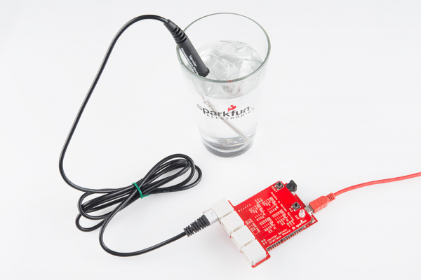
Measuring temperature is a quantity that crosses into nearly every area of science and engineering (except maybe computer science). Vernier sells a great stainless steel temperature probe that is accurate from -40 degrees C to +135 degrees C. According to their site, the sensor can handle up to 150 degrees C before it is damaged. For us in the U.S., this is about 300 degrees F. It's not quite safe to use as a meat thermometer in the oven, but it covers a pretty wide range for most scientific exporations.
The probe has a device called a thermistor that exhibits a change in resistance with respect to temperature. The Vernier probe uses a 20 kΩ NTC (negative thermal coefficient) Thermistor. As the temperature increases, the resistance drops.
The resistance vs. temperature relationship is non-linear and pretty complex, but it can be approximated using the Steinhart-Hart equation:
Where, RT is the resistance of the thermistor, and k0, k1, k2 are unique constants for the device. For the Vernier sensor:
k0 = 1.02119E-3
k1 = 2.22468E-4
k2 = 1.33342E-7
You can write your own function to convert the analog read value from the Arduino to a resistance.
Schematic:
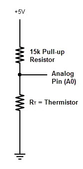
The Vernier Interface Shield has a 15k Pull-up Resistor on Vres. We can determine the resistance of the thermistor because this is a simple voltage divider circuit:
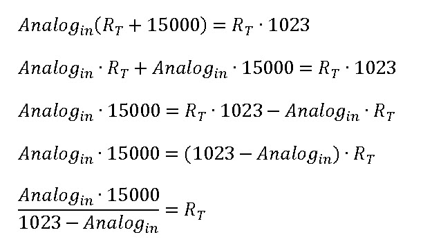
So - here's the derivation of the work and the algebra:
Example Code
The example below will collect data and display it to the Serial Monitor. After uploading this example sketch to your Arduino, open up a Serial Monitor to view the data.
This example code will take measurements at a rate of 2 samples per second. Modify the variable dataRate to adjust the sampling speed.
This code has a function called resistance() that converts the raw AnalogRead value to the resistance of the thermistor, and a function called steinharthart() that applies the Steinhart-Hart equation and returns a temperature in degrees Celsius.
language:c
    /*
VernierThermistor (v 2013.11)
 Reads the temperature from a Vernier Stainless Steel Temperature Probe (TMP-BTA)
 or Surface Temperature Sensor (STS-BTA) connected to the BTA connector.
 As written, the readings will be displayed every half second. Change the variable
 TimeBetweenReadings to change the rate.

 We use the Steinhart-Hart equation (in the function Thermistor) to determine temperature
 from the raw A/D converter reading. Because of the use of log functions, in the Steinhart-Hart
 equation, this sketch requires the math.h library.

 See www.vernier.com/engineering/stem/sensors/temperature-sensor/
 for more information on how thermistors are read.

 Modifications by B. Huang (Feb 2014)
 -------------------------
 Removed the use of delays in the loop() function. Uses a timeRef variable
 Added a variable called dataRate. dataRate describes the # of samples per second.
 Added separate functions for calculating the resistance of the thermistor and then applying the
 Steinhart-hart equation.

 See www.vernier.com/arduino for more information.
 */

float dataRate = 2;             // set # of samples per second.
const char delimiter = '\t';  // delimitter character

const int ThermistorPIN = A0; // A0 for Analog1 and A2 for Analog 2
float Temp;
int rawAnalogReading;

// Variables used in the code for calculations
unsigned long timeRef;    // reference for starting time

unsigned long timeInterval;
unsigned long ndx;        // index for data counter
unsigned long thermistor;

void setup()
{
  Serial.begin(9600);
  Serial.println("Vernier Format 2");
  Serial.println("Temperature Readings taken using Ardunio");
  Serial.println("Data Set");
  Serial.print("Time");
  Serial.print("\t"); //tab character
  Serial.println ("Temperature");
  Serial.print("seconds");
  Serial.print("\t"); // tab character
  Serial.println ("degrees C");
  timeInterval = 1000 / dataRate;  // calculates the timeInterval based on # of samples per second.
  timeRef = millis();
}

void loop()
{
  if ((millis()) >= ndx*timeInterval + timeRef)  // controls so only runs once per timeInterval
  {
    ndx++;
    //the print below does the division first to avoid overflows
    Serial.print((float)(millis() - timeRef) / 1000, 2);
    rawAnalogReading = analogRead(ThermistorPIN);  // reads raw analog value from Arduino
    thermistor = resistance(rawAnalogReading);     // converts raw analog value to a resistance
    Temp = steinharthart(thermistor);              // Applies the Steinhart-hart equation

    Serial.print(delimiter); //tab character
    Serial.println(Temp,1);   // display temperature to one digit
  }
}
unsigned long resistance(unsigned long rawAnalogInput)
/* function to convert the raw Analog Input reading to a resistance value
 * Schematic:
 *   [Ground] -- [thermistor] -------- | -- [15,000 ohm bridge resistor] --[Vcc (5v)]
 *                                     |
 *                                Analog Pin 0
 *
 * For the circuit above:
 * Resistance = ((rawAnalogInput*15000) /(1023 - rawAnalogInput))
 */
{
  unsigned long temp;  // temporary variable to store calculations in
  temp = (rawAnalogInput * 15000) / (1023 - rawAnalogInput);
  return temp; // returns the value calculated to the calling function.
}

float steinharthart(unsigned long resistance)
// function users steinhart-hart equation to return a temperature in degrees celsius.
/* Inputs ADC count from Thermistor and outputs Temperature in Celsius
 * There is a huge amount of information on the web about using thermistors with the Arduino.
 * Here we are concerned about using the Vernier Stainless Steel Temperature Probe TMP-BTA and the
 * Vernier Surface Temperature Probe STS-BTA, but the general principles are easy to extend to other
 * thermistors.
 * This version utilizes the Steinhart-Hart Thermistor Equation:
 *    Temperature in Kelvin = 1 / {A + B[ln(R)] + C[ln(R)]^3}
 *   for the themistor in the Vernier TMP-BTA probe:
 *    A =0.00102119 , B = 0.000222468 and C = 1.33342E-7
 *    Using these values should get agreement within 1 degree C to the same probe used with one
 *    of the Vernier interfaces
 *
 */
{
  float temp; // temporary variable to store calculations in
  float logRes = log(resistance);
  // calculating logirithms is time consuming for a microcontroller - so we just
  // do this once and store it to a variable.
  float k0 = 0.00102119;
  float k1 = 0.000222468;
  float k2 = 0.000000133342;

  temp = 1 / (k0 + k1 * logRes + k2 * logRes*logRes*logRes);
  temp = temp - 273.15;  // convert from Kelvin to Celsius
  return temp;
}
For more information on thermistors, take a look at Vernier's resource on making temperature measurements
Connecting an External Display
Adding an external display greatly enhances the ability to interface to the Vernier sensors independent of having a computer. The Arduino can be powered off a few AA batteries, and adding an LCD display will allow you to provide immediate feedback to the user.
What you'll need
- Male Break-away Headers
- Female Break-away Headers
- Serial LCD or Serial Seven Segment
- Hook-up wire - 6" M/F or 12" M/F
Recommended Reading / Useful Resources
Getting Started
You'll need to solder on the male break-away headers to access pins D0 and D1. These will be used to transmit / send data to your Serial display device. You will also need to add headers to the power pins (5V and GND). We suggest using the female headers for this, though. Having power and GND exposed creates a risk of a short-circuit. Thankfully, the Arduino has a PTC resettable fuse that will protect your computer and the Arduino from this, but it should still be avoided.
The example code will vary depending on the Serial device you are using. You will need to connect Power (5V), GND, and the Transmit (Pin 1) on the Vernier Shield to your serial display device. Remember: the TX line should go to the RX line on the serial device.
Storing Data to an SD Card
What you'll need
Recommended Reading / Useful Resources
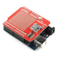
Adding an SD Card Interface to your Vernier shield is pretty simple. The SD Card shield will have to go below the Vernier Shield using a set of stack-able headers.
Upload this code to your shield. It logs raw voltage values of the sensors to a microSD Card, if you are using the SparkFun microSD Card Shield. If you are using your own SD Card shield implementation, double check the pin assignments for chipselect. On the SparkFun microSD Card Shield, chipselect is on pin 8.
This code example will read raw voltage levels from any analog Vernier Sensor that provides a voltage from 0 to 5V (this accounts for a majority of their sensors). Pressing the button (D12) will start the data collection for a time period defined by the variable duration. Data is logged to a file called "datalog.txt" and displayed to the Serial Monitor.
Upload the VernierSDStore sketch to your Arduino.
language:c
    /*
VernierShieldSDStore (v 2014.02)
Takes data from a Vernier Motion Detector connected to BTA connector.

The data is displayed to the serial monitor and saved to a file called datalog.txt

Data is currently displayed and stored as raw voltage levels from 0 to 5V. Currently working
integrate the AutoIDAnalog.ino code into this code so that data is automatically
calibrated.

Only the 5V analog signal is currently being used, but you can change the code to


See www.vernier.com/arduino for more information.
*/

#include <SD.h>      // includes the Arduino SD Library

// pin configurations for SparkFun Vernier Shield
// A1 = Analog 1
// A2 = Analog 2
#define A1_5V 0
#define A1_10V 1
#define A2_5V 2
#define A2_10V 3

char * filename = "datalog.txt";  /* sets the filename for data - change this
 if you want to use a different file name
 data will be concatenated onto the existing
 file if it exists */
float dataRate = 20.0;     // # of samples per second.
int duration = 5000;       // set the data collection duration in milliseconds
// default value is set to 5 seconds or 5000 milliseconds

unsigned long timeRef;      // reference for starting time
unsigned long timeInterval;
unsigned long elapsedTime;
unsigned long ndx = 0;

const int buttonPin = 12;   // digital button on Vernier Shield - used to start data collect
const int ledPin = 13;      // LED pin on Vernier Shield

/* Global Variable declarations for SD Card Shield */
const int chipSelect = 8;
File dataFile;

// variables used with VernierAnalogAutoID
//
int muxLSB = 10; //low byte of multiplexer
int muxMSB = 11; //high byte of multiplexer

int SensorRaw[2];
float SensorVoltage[2];
float VCC = 5.0;

void setup()
{
  // initialize serial communication at 9600 bits per second:
  Serial.begin(9600);

  // set the timeInterval based on dataRate
  timeInterval = 1E3 / dataRate;

  // initialize the buttonPin as an INPUT with a pull-up resistor
  pinMode(buttonPin, INPUT_PULLUP);
  pinMode(muxLSB, OUTPUT);
  pinMode(muxMSB, OUTPUT);

  Serial.println("*************************************************");
  Serial.println("Push button (D12) to start data collection.");
  Serial.println("Use reset button to reset / stop data collection.");
  Serial.println("*************************************************");

  while(digitalRead(buttonPin) == HIGH)
  {
    // holding loop until the button goes low.
  }

  /***********************
   * / Setup SD Card
  /***********************/
  pinMode(chipSelect, OUTPUT);

  Serial.print("Initializing SD card...");

  // see if the card is present and can be initialized:
  if (!SD.begin(chipSelect))
  {
    Serial.println("Card failed, or not present");
    // don't do anything more:
    return;
  }
  Serial.println("card initialized.");

  Serial.println();

  /***********************
   * / Print data header
  /***********************/
  Serial.println(" ");
  Serial.println("Vernier Format 2");
  Serial.println("Raw Readings taken using Ardunio");
  Serial.println("Data Set");
  Serial.print("Time");

  Serial.print("\t"); //tab character
  Serial.print ("Chan1");
  Serial.print("\t"); //tab character
  Serial.print("Chan2");


  Serial.println("");
  Serial.print("seconds");

  Serial.print("\t"); //tab character
  Serial.print ("V");
  Serial.print("\t"); //tab character
  Serial.print ("V");
  Serial.println();

  /*************************
   * / Print header to SD Card
  /*************************/

  dataFile = SD.open(filename, FILE_WRITE);
  if (dataFile) // if it opens sucessfully
  {
    dataFile.println("Vernier Format 2");
    dataFile.println("Raw Readings taken using Ardunio");
    dataFile.println("Data Set");
    dataFile.print("Time");
    // query the channel numbers

    // print sensor name -- data will be displayed in raw and voltage
    dataFile.print("\t"); //tab character
    dataFile.print("Chan1");
    dataFile.print("\t"); //tab character
    dataFile.print("Chan2");
    dataFile.println();

    // display the units
    dataFile.print("seconds");

    dataFile.print("\t");
    dataFile.print("V");
    dataFile.print("\t");
    dataFile.print("V");

    dataFile.close(); // close the datafile
  }
  else  // if(datafile) -- error opening SD card
  {
    Serial.println("error opening file.");
    Serial.println();
  }

  digitalWrite(ledPin, HIGH);
  timeRef = millis();
  ndx = 0;   // datapoint index
} // end setup

void loop()
{
  unsigned long currTime = millis();  // record current Time
  if ((currTime - timeRef) <= (duration))     // controls the duration of the data collection
  {
    if (currTime >= ndx*timeInterval + timeRef)  // controls so only runs once per timeInterval
    {
      ndx++;
      digitalWrite(ledPin, LOW); // blink the LED off to show data being taken.

      // Read in sensor values
      SensorRaw[0] = analogRead(A1_5V);
      SensorRaw[1] = analogRead(A2_5V);

      // Convert to voltage values
      SensorVoltage[0] = SensorRaw[0]*VCC/1023.0;
      SensorVoltage[1] = SensorRaw[1]*VCC/1023.0;
/* // uncomment these lines of code to use the +/- 10V sensors
      SensorRaw[0] = analogRead(A1_10V);
      SensorRaw[1] = analogRead(A2_10V);

      // Convert to voltage values (20V range, -10V offset)
      SensorVoltage[0] = SensorRaw[0]*20.0/1023.0 - 10.0;
      SensorVoltage[1] = SensorRaw[1]*20.0/1023.0 - 10.0;

*/

      dataFile = SD.open(filename, FILE_WRITE);
      // if the file is available, write to it:
      if (dataFile)
      {
        dataFile.print((currTime - timeRef)/ 1E3, 3);  // 4 decimal places
        dataFile.print("\t");
        dataFile.println(SensorVoltage[0]);
        dataFile.print("\t");
        dataFile.println(SensorVoltage[1]);
        dataFile.close();
      }

      // if the file isn't open, pop up an error:
      else
      {
        Serial.println("Error opening file.");
      }
      // Serial print to the serial monitor
      Serial.print((currTime - timeRef) / 1E3, 3);
      Serial.print("\t"); // tab character
      Serial.print(SensorVoltage[0]);
      Serial.print("\t");
      Serial.print(SensorVoltage[1]);
      Serial.println();

      digitalWrite(ledPin, HIGH); // turn the LED back on to show data collection
      // duration is still running.
    }
  }
  else  // duration is complete -- wait and reset if button is pressed
  {
    digitalWrite(ledPin, LOW);    // turn off LED to show data collection is done.
    while(digitalRead(buttonPin) == HIGH)
    {
      // holding loop until the button goes low.
    }
    // reset counters and timeRef
    digitalWrite(ledPin, HIGH);
    ndx = 0;
    timeRef = millis();

  }
} // end of loop
Resources and Going Further
We hope that these examples will get you going on digging into the details of data collection and calibration. Vernier has been incredibly helpful with this collaboration. They have a wealth of resources on their site, as well:
Please send an e-mail to education@sparkfun.com if you'd like to share what you are doing with Vernier Sensors and Arduino or if you have any questions or problems with your board.
