Vernier Photogate
 bri_huang
Introduction
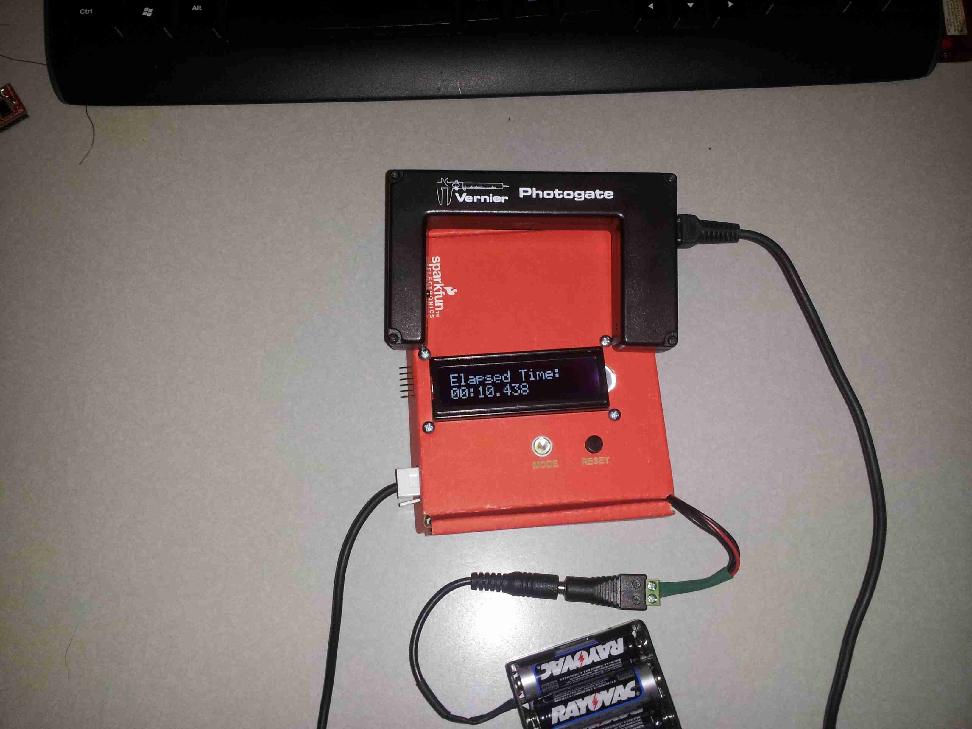
In this project tutorial, we will show you how to create a cheap but accurate photogate (similar to the one pictured below) for use in classroom applications, particularly physics experiments.
This project started as part of a grant I co-authored for my classroom. The grant, called Physics and Instructional Resource (PAIR), is designed to help support physics teachers in need of content or material resources. The grant pairs together a classroom teacher with a physics professional to develop new materials and resources for the classroom. I had the idea of integrating an Arduino with and LCD screen to create a hand-held photogate timer like this one:
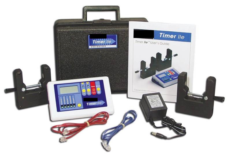
These smart timer units are costly ($200-$300 each), they require a power adapter, and the user interface is not customizable. With the flexibility and low cost of the Arduino platform, we set out to develop a unique solution that we could integrate into a Physics First program for freshman at the high school. Our school has access to a large supply of Vernier hardware and photogates, but but the use of these are restricted to the physics lab where we have computers to perform the data collection and analysis.
I was looking for a simple, portable device to interface these sensors. Using an Arduino seemed like a pretty straight-forward solution.
Required Materials
If you would like to follow along an build your own photogate timer(s), you will need the following:
Suggested Reading
This tutorial builds on several other concepts. Please familiarize yourself with the concepts below if you are familiar already.
Our First Prototype
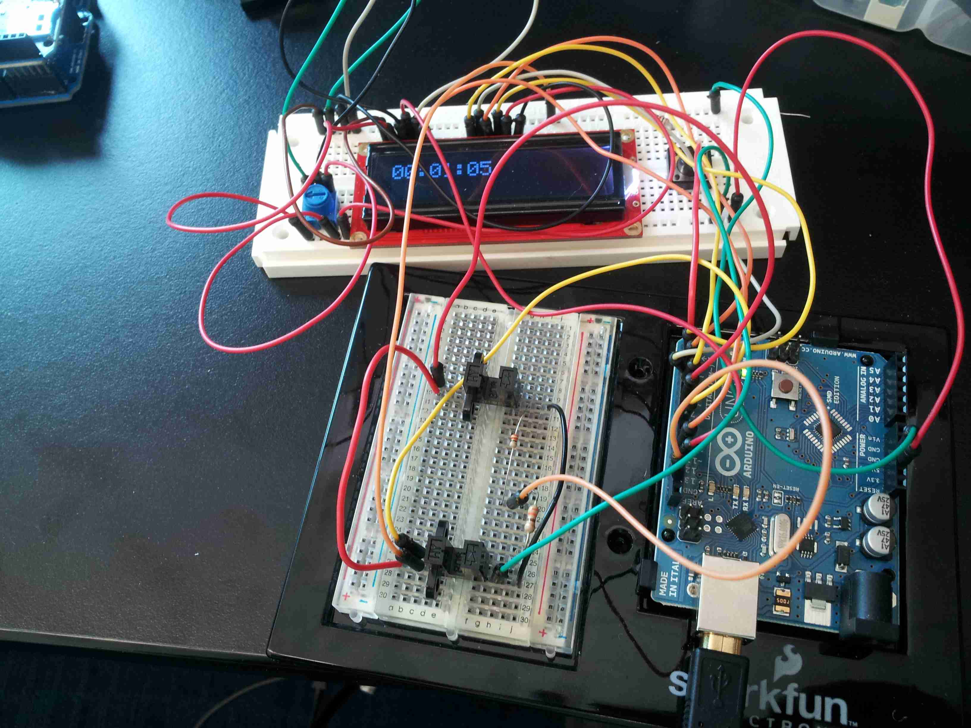
This prototype was a great success. We modified stopwatch code from Dan Thompson. Unfortunately, this prototype was far from ready to be put in the hands of kids. I still needed to find a cleaner, tighter solution. The first part I needed to replace were the small photo-interrupers (photogates) you see in this picture.
Photogates
We started our original prototype design with these photo-interrupters that we found on Amazon. These little modules are great. They have 4 leads and there is a small IR LED on one side. The other side is an IR receiver.
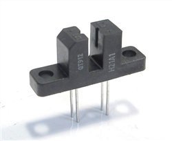
The only drawback to using these devices is that the IR LED still needs a current limiting resistor. I figured that out the hard way! They aren't easy to mount, and they have a really small gate opening. Digging around in the closets at the school I discovered several drawers full of photogates from Vernier. I would guess that several other schools might be in the same situation.
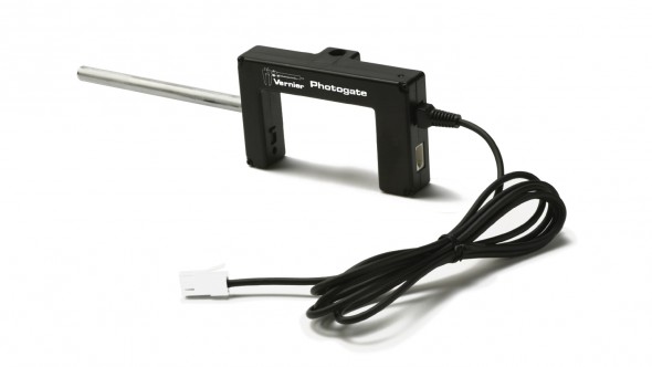
These photogates are fantastic. The detectors each have a Schmidt trigger built in and a LED to indicate when the gate is broken. The only drawback is that Vernier has a special British Telecom connector on their devices. The photogate uses a left-hand version of this connector. We had an option to simply cut the ends off, but then these photogates would not be usable with the LabPro devices in our Physics lab. Thankfully, Vernier sells these breadboard connectors. Using these I could build an interface directly to an Arduino. I just had to figure out the sensor pin-outs.
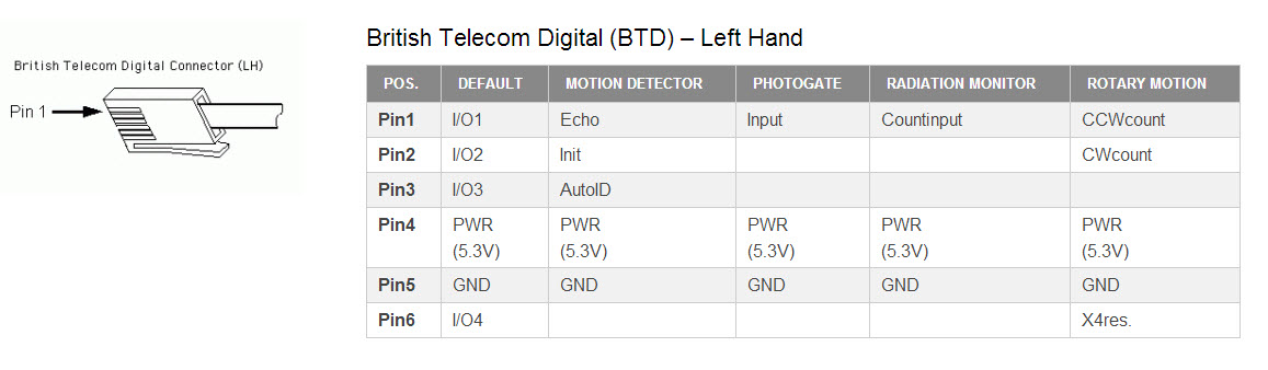
Sensor Pin-Outs
Vernier provides sensor pin-out definitions for their British Telecom digital connector.
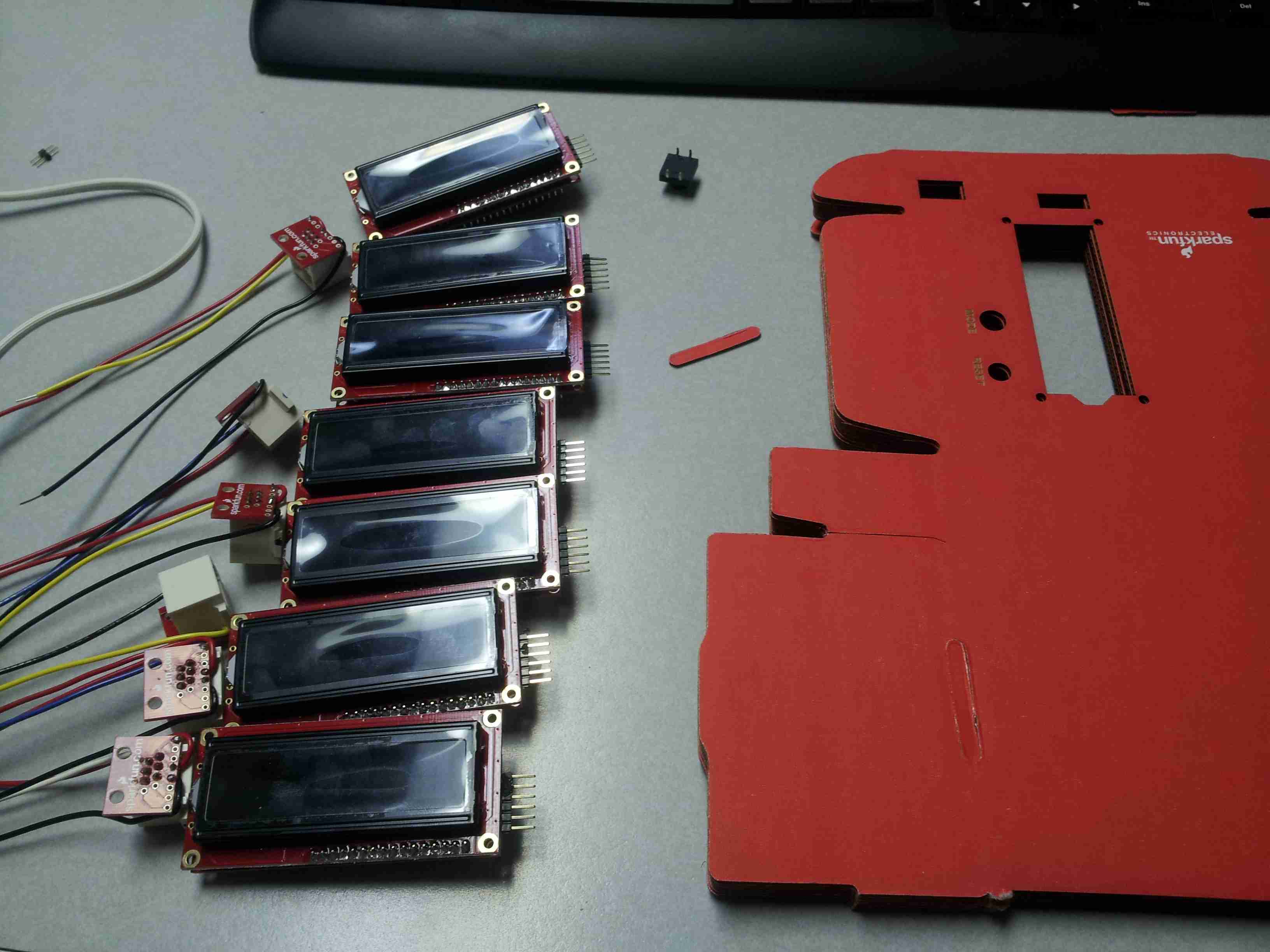
Looking for a cleaner LCD / Arduino shield solution, I stumbled across the Serial-Enabled LCD kit.
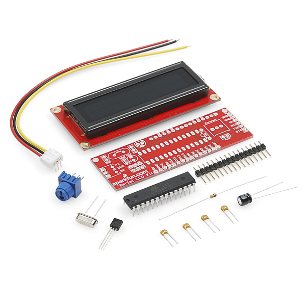
This is quite the misnomer for what it is. SparkFun has used a standard ATMega 328 chip controlling the serial-to-parallel interface. Basically, this is an Arduino with an LCD - no extra shield, and no extra frills needed. I called up some friends and we soldered up 8 of these guys in one night. While we were at it, we soldered on a right-angle male header to the side so that we could access the FTDI programming pins, too.

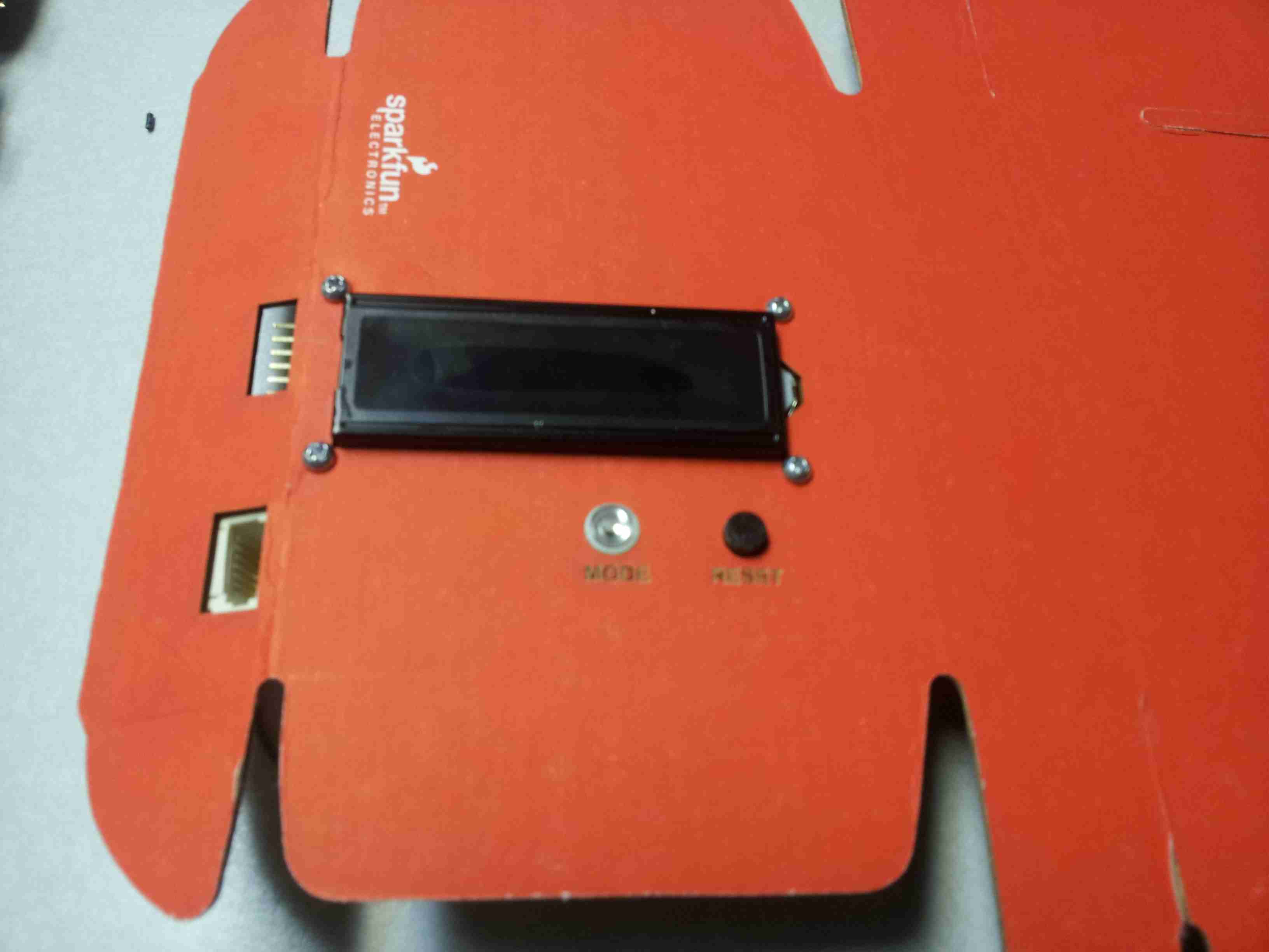
Putting it all Together
I made several measurements for the LCD. Links to the drawing files can be found below. I added a couple buttons for mode/select, reset, and I cut holes on the side to access the FTDI programming pins.
Cutting out the Case
The initial grant stipulated we build up 8 of these units to test. So, I set up an assembly line to do this.
I added an LED button for the MODE switch and a standard 12 mm push button for the RESET.
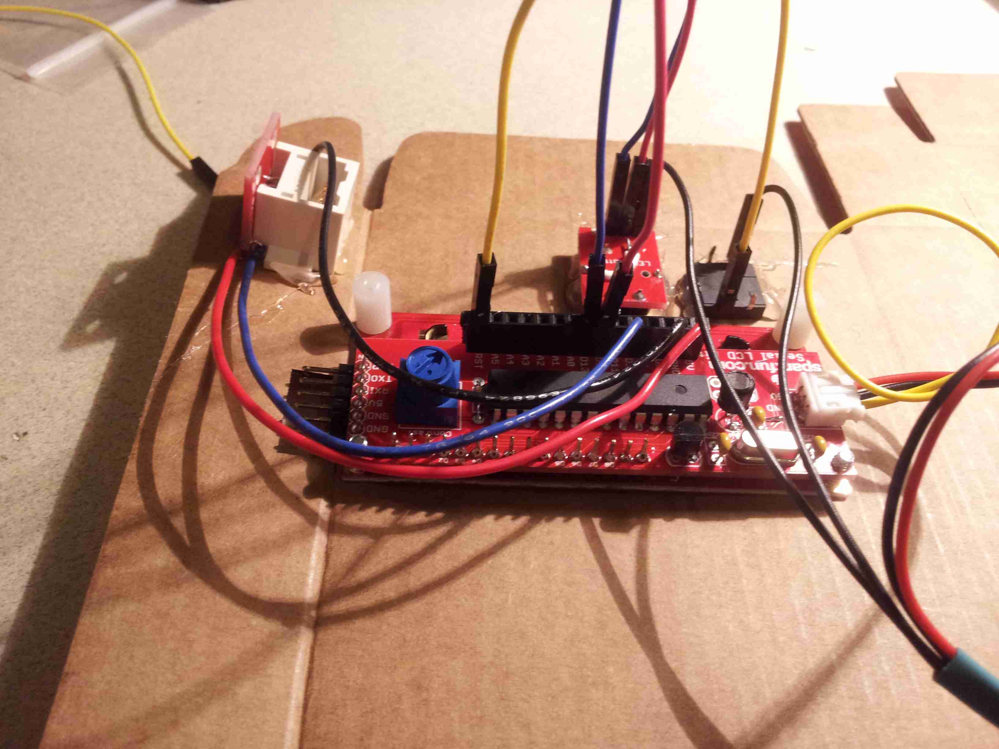
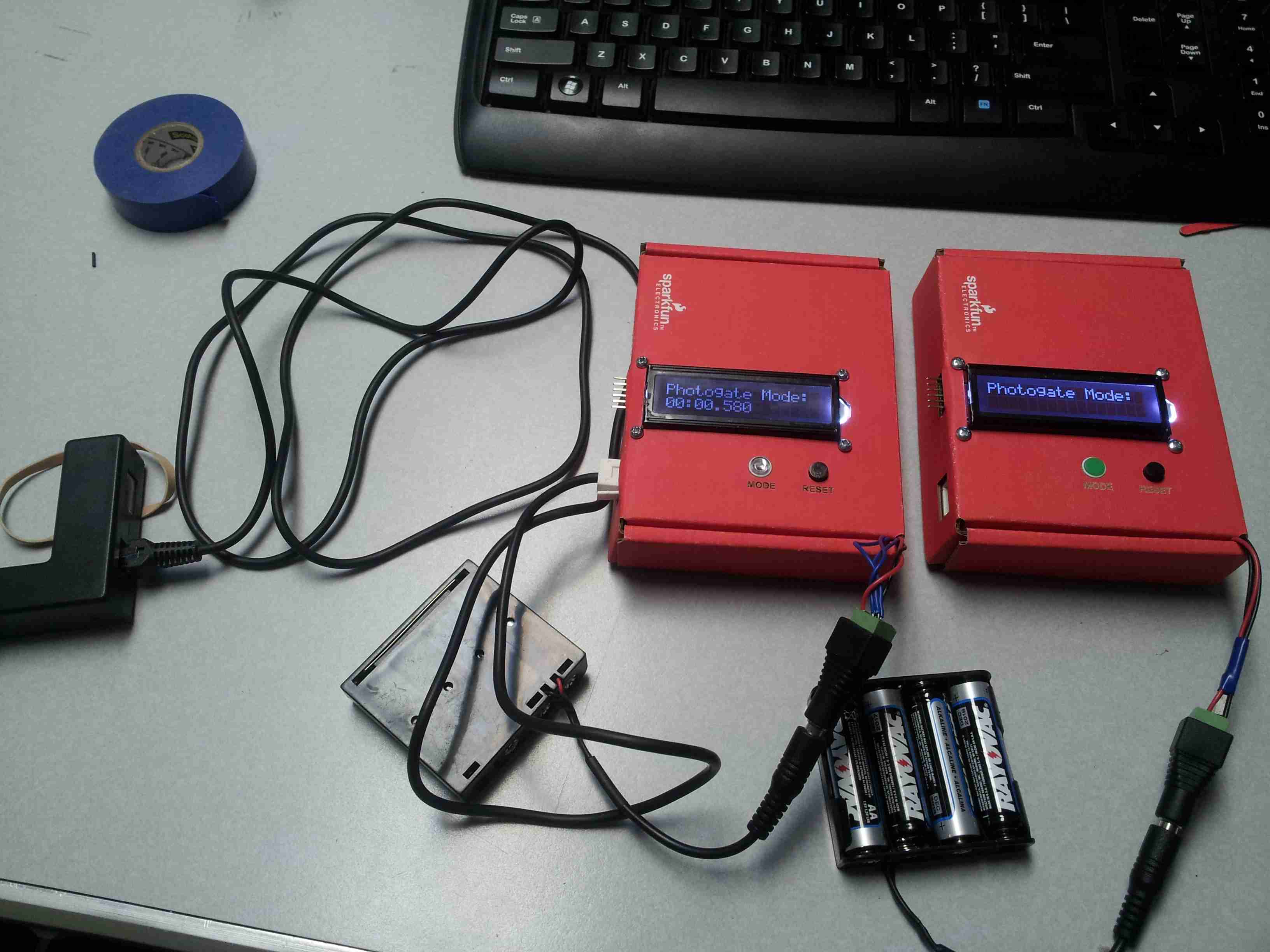
The Wiring
Using some standard 18 AWG hook-up wire I connected up the Vernier BTD Connector, two push buttons, and added a female barrel jack adaptor for power.
Since you probably can't tell where all of these wires are going, here is a simplified Fritzing diagram illustrating the connections.
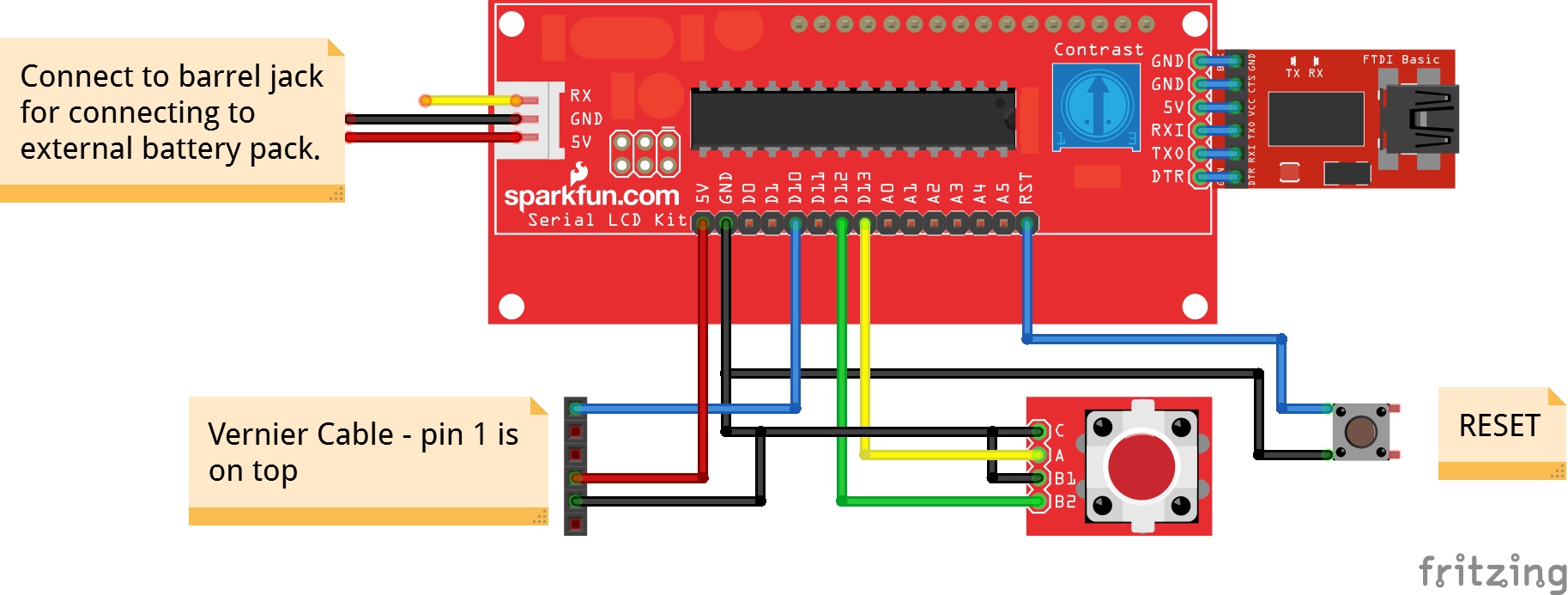
Click here for the Fritzing drawing.
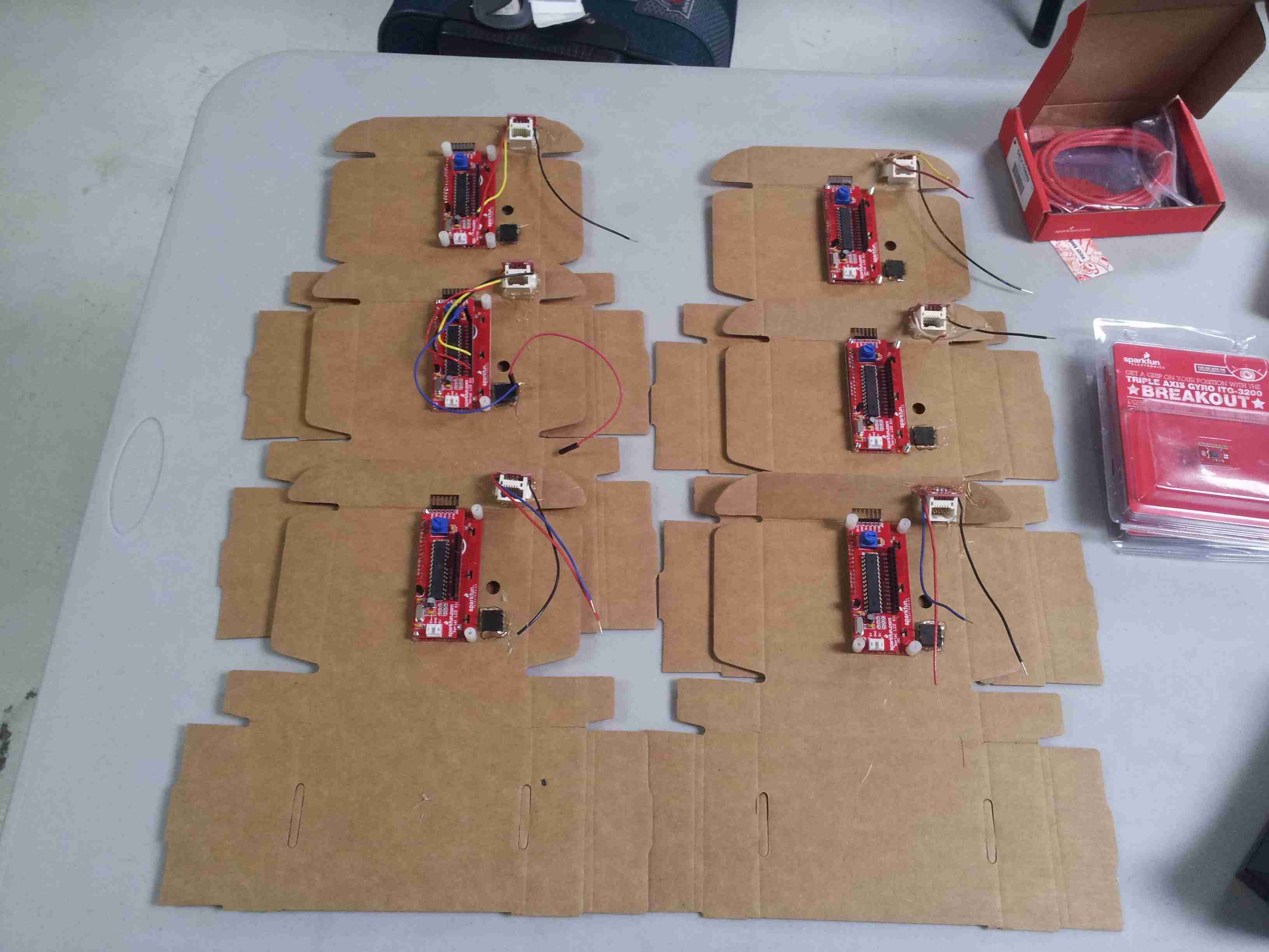
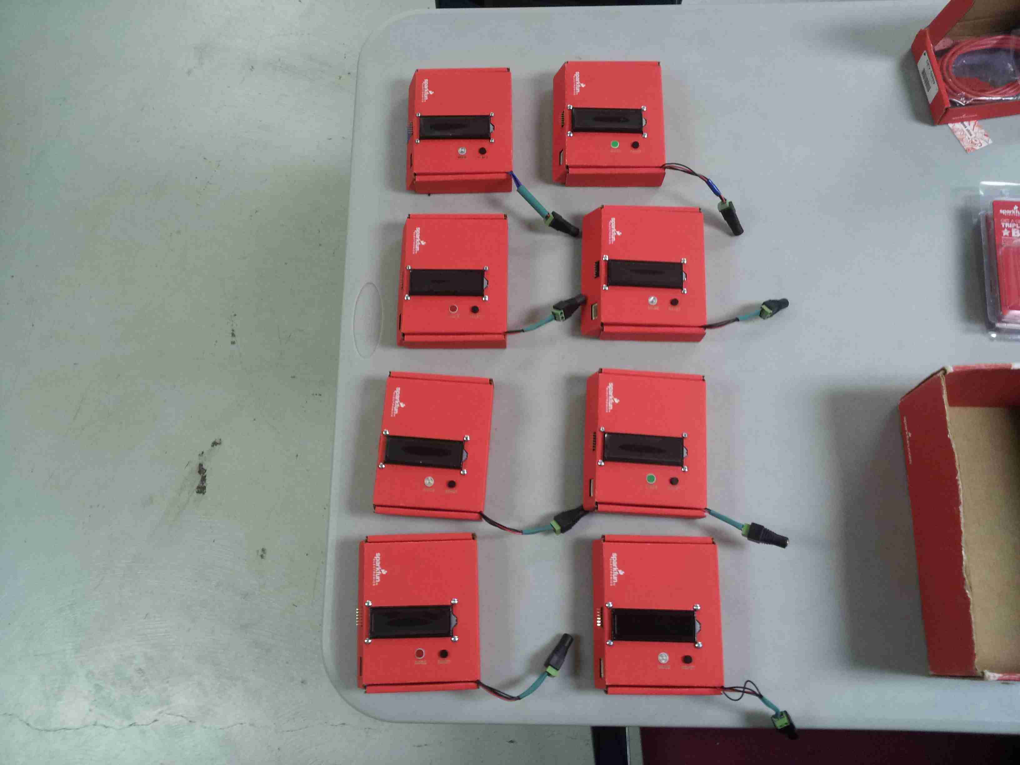
Assembly Complete
Here are the 8 fully assembled photogate timer units. Ready for programming.
The Code
There are two primary uses for photogates in a physics classroom. The first mode - sometimes called GATE mode - shows the amount of time that the photogate is broken. The second mode is typically called PULSE mode. This mode will start the timer when the gate is first broken, and then stop the timer when the gate is broken again. This works great if you have daisy-chained photogates.
If you're interested, Vernier has a nice Introduction to Photogate Timing Tutorial.
Starting with the initial code base we used with our prototype we integrated a MODE button to select between the various operations, and we also incorporated a RESET feature. The code is currently setup to support 3 modes of operation.
- Mode 1 - GATE Mode
- Mode 2 - PULSE Mode
- Mode 3 - Standard Stopwatch mode (start/stop using the MODE button)
Here's the latest version of the code that we developed, or you can download a copy here:
language:c
/*
  LCD Photogate Timer
  Written by:  Brian Huang
  Date:  05.06.13
  Sparkfun Electronics

 Code based on: http://danthompsonsblog.blogspot.com/2008/11/timecode-based-stopwatch.html
 Coded by: arduinoprojects101.com

 3 modes of operation:
   Mode 1:  Displays the time that the gate is broken.
   Mode 2:  Breaking the gate starts the timer, and breaking it again, stops the timer - for use with Vernier photogates daisy-chained together.
   Mode 3:  Standard Start/Stop Stopwatch.  Start & Stop triggered with the Mode Button.

Future work to be done:
   Store data into an array so that multiple instances of start/stop can be tracked. This can be used for measuring acceleration.


*/
// include the library code:
#include <LiquidCrystal.h>
#include <EEPROM.h>

int ledPin = 13;                    // LED connected to digital pin 13
int gatePin = 10;                   // gate on pin 8
int buttonPin = 12;                 // mode button

int LEDstate = LOW;                    // previous value of the LED

int gateState;                      // variable to store gate state
int lastgateState;                  // variable to store last gate state

int buttonState;                    // variable to store button state
int lastButtonState;                    // variable to store button state

int mode = 1;

boolean refresh = false;                    // condition for refresh - timer is timing

int frameRate = 1000;               // the frame rate (frames per second) at which the stopwatch runs - Change to suit
long interval = 1;                  // blink interval
long previousMillis = 0;            // variable to store last time LED was updated
long startTime ;                    // start time for stop watch
long elapsedTime ;                  // elapsed time for stop watch

long dataBuffer[127]={
}
;                  // elapsed time for stop watch
int dataIndex=0;

int fractional;                     // variable used to store fractional part of Frames
int fractionalSecs;                 // variable used to store fractional part of Seconds
int fractionalMins;                 // variable used to store fractional part of Minutes
int fractionalHrs;                 // variable used to store fractional part of Minutes

int elapsedFrames;                  // elapsed frames for stop watch
int elapsedSeconds;                 // elapsed seconds for stop watch
int elapsedMinutes;                 // elapsed Minutes for stop watch
int elapsedHours;                   // elapsed Hours for stop watch

char buf[10];                       // string buffer for itoa function

// --- EEPROM ADDRESS DEFINITIONS
#define LCD_BACKLIGHT_ADDRESS 1  // EEPROM address for backlight setting
#define BAUD_ADDRESS 2  // EEPROM address for Baud rate setting
#define SPLASH_SCREEN_ADDRESS 3 // EEPROM address for splash screen on/off
#define ROWS_ADDRESS 4  // EEPROM address for number of rows
#define COLUMNS_ADDRESS 5  // EEPROM address for number of columns

// --- SPECIAL COMMAND DEFINITIONS
#define BACKLIGHT_COMMAND 128  // 0x80
#define SPECIAL_COMMAND 254 // 0xFE
#define BAUD_COMMAND 129  // 0x81

// --- ARDUINO PIN DEFINITIONS
uint8_t RSPin = 2;
uint8_t RWPin = 3;
uint8_t ENPin = 4;
uint8_t D4Pin = 5;
uint8_t D5Pin = 6;
uint8_t D6Pin = 7;
uint8_t D7Pin = 8;
uint8_t BLPin = 9;

char inKey;  // Character received from serial input
uint8_t Cursor = 0;  // Position of cursor, 0 is top left, (rows*columns)-1 is bottom right
uint8_t LCDOnOff = 1;  // 0 if LCD is off
uint8_t blinky = 0;  // Is 1 if blinky cursor is on
uint8_t underline = 0; // Is 1 if underline cursor is on
uint8_t splashScreenEnable = 1;  // 1 means splash screen is enabled
uint8_t rows = 2;  // Number rows, will be either 2 or 4
uint8_t columns = 16; // Number of columns, will be 16 or 20
uint8_t characters; // rows * columns


// initialize the LCD at pins defined above
LiquidCrystal lcd(RSPin, RWPin, ENPin, D4Pin, D5Pin, D6Pin, D7Pin);

/* ----------------------------------------------------------
 In the setup() function, we'll read the previous baud,
 screen size, backlight brightness, and splash screen state
 from EEPROM. Serial will be started at the proper baud, the
 LCD will be initialized, backlight turned on, and splash
 screen displayed (or not) according to the EEPROM states.
 ----------------------------------------------------------*/

void setup()
{

  pinMode(ledPin, OUTPUT);         // sets the digital pin as output
  pinMode(gatePin, INPUT);       // not really necessary, pins default to INPUT anyway
  pinMode(buttonPin, INPUT_PULLUP);       // not really necessary, pins default to INPUT anyway
  digitalWrite(gatePin, HIGH);   // turn on pullup resistors. Wire button so that press shorts pin to ground.
  Serial.begin(9600);
  rows = 2;
  columns = 16;

  // set up the LCD's number of rows and columns:
  lcd.begin(columns, rows);

  // Set up the backlight
  pinMode(BLPin, OUTPUT);

  setBacklight(EEPROM.read(LCD_BACKLIGHT_ADDRESS));
  lcd.clear();
  lcd.setCursor(0, 0);
  lcd.print("Photogate Timer");
  lcd.setCursor(0, 1);
  lcd.print("Mode - ");
  lcd.print(mode);
}

/*----------------------------------------------------------
 ----------------------------------------------------------*/
void loop()
{
  gateState = digitalRead(gatePin); // Check for button press, read the button state and store -- LOW is unblocked.
  buttonState = digitalRead(buttonPin);

  if (mode < 3)
  {
    if((buttonState== LOW) && (lastButtonState == HIGH) && (refresh == false) && (mode < 3))
    {
      // if button is pressed, increment the mode -- up to mode #3
      if (mode <3)
        mode++;
      lcd.clear();
      lcd.setCursor(0, 0);
      lcd.print("Photogate Timer");
      lcd.setCursor(0, 1);
      lcd.print("Mode - ");
      lcd.print(mode);

      lastButtonState = buttonState;
    }
    else
    {
      lastButtonState = buttonState;
    }
  }

  switch(mode)
  {
  case 1:
    if (gateState == LOW && lastgateState == HIGH  &&  refresh == false)
    {
      lcd.clear();
      lcd.setCursor(0, 0);
      lcd.print("Photogate - 1");
      lcd.setCursor(0, 1);
      startTime = millis();                               // store the start time
      Serial.print(previousMillis - startTime);
      dataBuffer[dataIndex] = startTime;
      dataIndex++;

      refresh = true;                                  // turn on refresh while timing
      lastgateState = gateState;                    // store gateState in lastgateState, to compare next time
      digitalWrite(ledPin, HIGH);
    }

    // check for a high to low transition if true then found a new button press while clock is running - stop the clock and report
    else if (gateState == HIGH && lastgateState == LOW && refresh == true){
      refresh = false;                                    // turn off refresh, all done timing
      lastgateState = gateState;                       // store gateState in lastgateState, to compare next time

      digitalWrite(ledPin, LOW);
      lcd.clear();                                         // clear the LCD
      lcd.print("Elapsed Time:");
      lcd.setCursor(0,1);
      displayElapsedTime();
    }
    else
      lastgateState = gateState;                  // store gateState in lastgateState, to compare next time
      if ((millis() - previousMillis > interval) & (refresh == true ))
      {
      lcd.setCursor(0,1);
      previousMillis = millis();                    // remember the last time we blinked the LED
      Serial.print(previousMillis - startTime);
      elapsedTime =   previousMillis - startTime;         // store elapsed time
      dataBuffer[dataIndex] = previousMillis;
      dataIndex++;
      displayElapsedTime();

    }
    break;

  case 2:
    if (gateState == LOW && lastgateState == HIGH  &&  refresh == false)
    {
      lcd.clear();
      lcd.setCursor(0, 0);
      lcd.print("Photogate - 2");
      startTime = millis();                               // store the start time

      // toggle refresh flag
      refresh = true;
      digitalWrite(ledPin, HIGH);
      lastgateState = gateState;                    // store gateState in lastgateState, to compare next time
    }

    // check for a high to low transition if true then found a new button press while clock is running - stop the clock and report
    else if (gateState == LOW && lastgateState == HIGH  &&  refresh == true)
    {
      refresh = false;                                    // turn off refresh, all done timing
      digitalWrite(ledPin, LOW);
      lastgateState = gateState;                       // store gateState in lastgateState, to compare next time

        // store data into an array - for later
      //    dataBuffer[dataIndex] = elapsedTime;
      //    dataIndex++;

      lcd.clear();                                         // clear the LCD
      lcd.print("Elapsed Time:");
      lcd.setCursor(0,1);
      displayElapsedTime();
    }

    else
    {
      lastgateState = gateState;                  // store gateState in lastgateStategateStategateState, to compare next time
    }

    if ((millis() - previousMillis > interval) & (refresh == true))
    {
      previousMillis = millis();                    // remember the last time we blinked the LED
      elapsedTime =   millis() - startTime;         // store elapsed time
      lcd.setCursor(0, 1);
      displayElapsedTime();
    }
    break;
  case 3:
    Serial.print(buttonState);
    Serial.print("\t");
    Serial.print(lastButtonState);
    Serial.print("\t");
    Serial.println(refresh);
    delay(100);

    if ((buttonState == LOW) && (lastButtonState == HIGH)  &&  (refresh == false))
    {
      lcd.clear();
      lcd.setCursor(0, 0);
      lcd.print("Stopwatch Mode");
      startTime = millis();                               // store the start time

      // toggle refresh flag
      refresh = true;
      digitalWrite(ledPin, HIGH);
      lastButtonState = buttonState;                    // store gateState in lastgateState, to compare next time
      Serial.println("Start");

    }

    // check for a high to low transition if true then found a new button press while clock is running - stop the clock and report
    else if ((buttonState == LOW) && (lastButtonState == HIGH)  &&  (refresh == true))
    {
      refresh = false;                                    // turn off refresh, all done timing
      digitalWrite(ledPin, LOW);
      lastButtonState = buttonState;                       // store gateState in lastgateState, to compare next time

        lcd.clear();                                         // clear the LCD
      lcd.print("Elapsed Time:");
      lcd.setCursor(0,1);
      displayElapsedTime();
      Serial.println("Stop");

    }
    else
    {
      lastButtonState = buttonState;                  // store gateState in lastgateStategateStategateState, to compare next time
      Serial.println("got here...");
    }

    if ((millis() - previousMillis > interval) & (refresh == true))
    {
      previousMillis = millis();                    // remember the last time we blinked the LED
      elapsedTime =   millis() - startTime;         // store elapsed time
      lcd.setCursor(0, 1);
      displayElapsedTime();
    }
    break;
  }
  // check for a low to high transition if true then found a new button press while clock is not running - start the clock
}

void displayElapsedTime()
{

  elapsedMinutes = (elapsedTime / 60000L);      // divide by 60000 to convert to minutes - then cast to an int to print
  elapsedSeconds = (elapsedTime / 1000L);       // divide by 1000 to convert to seconds - then cast to an int to print
  elapsedFrames = (elapsedTime / interval);     // divide by 40 to convert to 1/25 of a second - then cast to an int to print
  fractional = (int)(elapsedFrames % frameRate);// use modulo operator to get fractional part of 25 Frames
  fractionalSecs = (int)(elapsedSeconds % 60L); // use modulo operator to get fractional part of 60 Seconds
  fractionalMins = (int)(elapsedMinutes % 60L); // use modulo operator to get fractional part of 60 Minutes

  // this is while the timer is running.
  if (fractionalMins < 10)
  {                     // pad in leading zeros
    lcd.print("0");                             // add a zero
  }

  lcd.print(itoa(fractionalMins, buf, 10));   // convert the int to a string and print a fractional part of 60 Minutes to the LCD
  lcd.print(":");                             //print a colan.

  if (fractionalSecs < 10)
  {                     // pad in leading zeros
    lcd.print("0");                             // add a zero
  }

  lcd.print(itoa(fractionalSecs, buf, 10));   // convert the int to a string and print a fractional part of 60 Seconds to the LCD
  lcd.print(".");                             //print a colan.

  if (fractional < 100)
  {                         // pad in leading zeros
    lcd.print("0");                             // add a zero
  }

  if (fractional < 10)
  {                         // pad in leading zeros
    lcd.print("0");                             // add a zero
  }
  lcd.print(itoa((fractional), buf, 10));  // convert the int to a string and print a fractional part of 25 Frames to the LCD
}


void setBacklight(uint8_t backlightSetting)
{
  analogWrite(BLPin, backlightSetting);
  EEPROM.write(LCD_BACKLIGHT_ADDRESS, backlightSetting);
}

/* ----------------------------------------------------------
 setBaudRate() is called from SpecialCommands(). It receives
 a baud rate setting balue that should be between 0 and 10.
 The baud rate is then set accordingly, and the new value is
 written to EEPROM. If the EEPROM value hasn't been written
 before (255), this function will default to 9600. If the value
 is out of bounds 10<baud<255, no action is taken.
 ----------------------------------------------------------*/
void setBaudRate(uint8_t baudSetting)
{
  // If EEPROM is unwritten (0xFF), set it to 9600 by default
  if (baudSetting==255)
    baudSetting = 4;

  switch(baudSetting)
  {
  case 0:
    Serial.begin(300);
    break;
  case 1:
    Serial.begin(1200);
    break;
  case 2:
    Serial.begin(2400);
    break;
  case 3:
    Serial.begin(4800);
    break;
  case 4:
    Serial.begin(9600);
    break;
  case 5:
    Serial.begin(14400);
    break;
  case 6:
    Serial.begin(19200);
    break;
  case 7:
    Serial.begin(28800);
    break;
  case 8:
    Serial.begin(38400);
    break;
  case 9:
    Serial.begin(57600);
    break;
  case 10:
    Serial.begin(115200);
    break;
  }
  if ((baudSetting>=0)&&(baudSetting<=10))
    EEPROM.write(BAUD_ADDRESS, baudSetting);
}
Use in the Classroom
Unfortunately, I was not able to present the photogates to my class at Overland High School. However, Mr. Ryan O'Block, one my colleagues at the school, was able to use these in his Freshman Earth and Physical Science class.
Here is the activity that he used with his class:
Class use of the photogate timers:
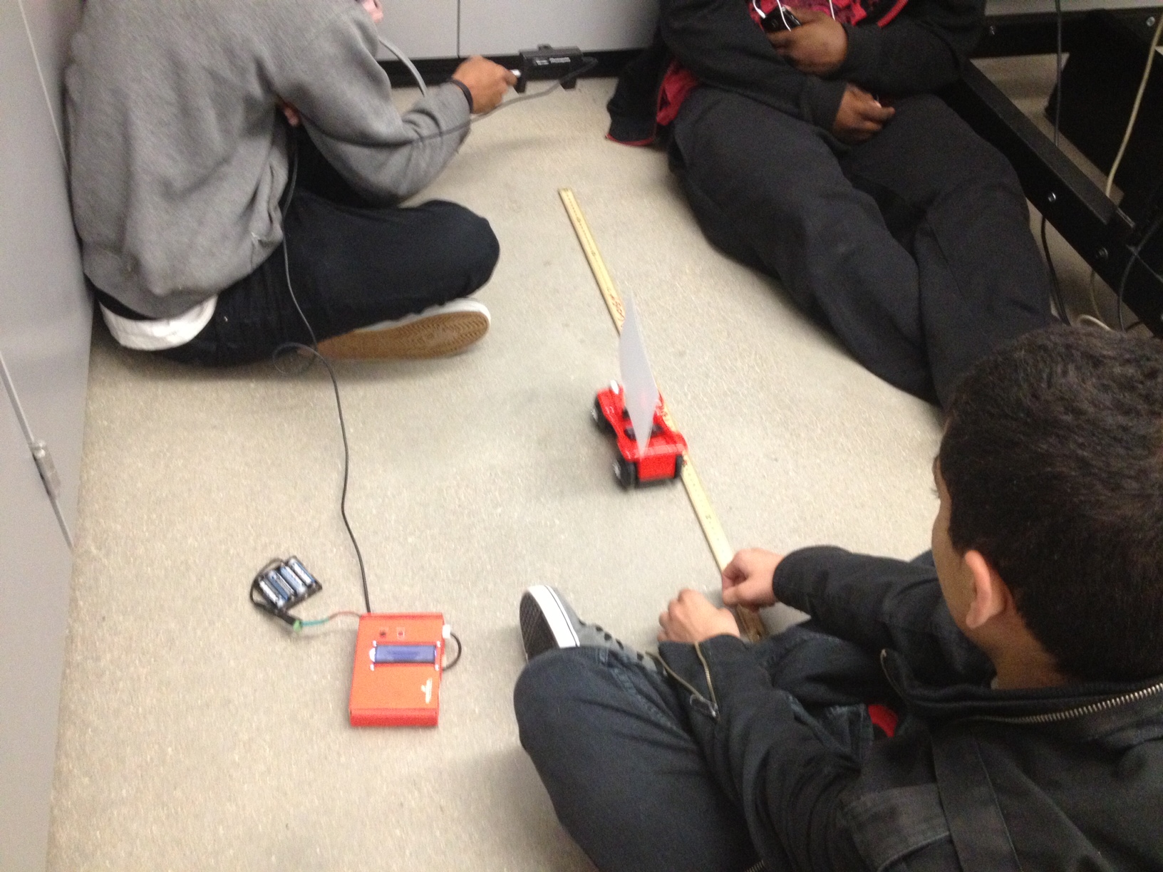
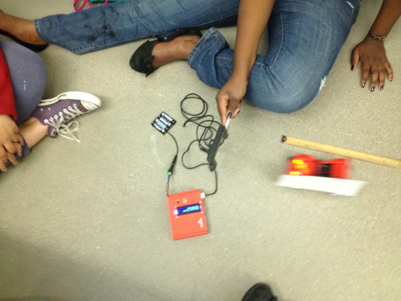
Using photogates provides students with reliable and repeatable data for measuring time. The reaction-time latency and error associated with simple stop-watches often masks the fundamental concepts around learning about position and time. This simple tool can be reproduced easily and at a very low cost to schools.
The next steps are to improve the code and add the ability to measure and store multiple data points. This feature would allow students to calculate the increase in average velocity and determine an average acceleration over a given time period.
If you are interested in more detail, please leave us a comment. Or, if you have ideas of improvements or suggestions, we would love to hear them.