Vernier Shield Hookup Guide
 bri_huang
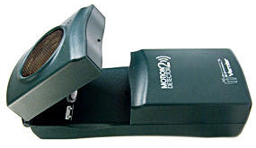
Example 3 - Motion Detector
Vernier's motion detector sensor is one of the most popular sensors used in classrooms. It uses a ultrasonic transducer similar ones used in older auto-focusing Polaroid cameras.
Combined with a graphing utility, it allows students to immediately see how position varies with time and how the slope of this graph is related to quantities such as velocity and acceleration.
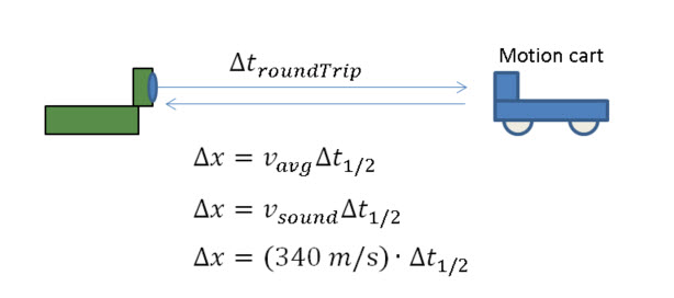
The motion detector uses echo-location or sonar to determine the distance of objects in front of the sensor. It works by emitting an ultrasonic pulse and then listening for the echo of the pulse from the reflection off objects. The Vernier motion detector uses two pins for this:
Init (Pin 2 on the BTD connector)
Echo (Pin 1 on the BTD connector)
On the Vernier shield, we have these pins tied to:
| Digital 1 | Digital 2 | ||
| INIT | 4 | 8 | Trigger pin to send the ultrasonic pulse. |
| ECHO | 3 | 7 | Listen to this pin for the echo return / reflection. |
Using the Arduino function micros, we can catch the time of the echo to an accuracy of 1 us. If we assume that sound travels at a speed of about 340 m/s, this translates to a round-trip accuracy of better than 1 mm.
Because we know that sound travels at a constant speed in a uniform medium, we can use simple kinematics to determine the distance the reflected sound travelled. In our code, we assume that the speed of sound is nominally 340 m/s. If you care to account for differences in temperature, hyperphysics has a great tool to calculate and adjust for differences in temperature.
Code example
The following code example has been adapted from the Vernier github repository. This sketch will record at a dataRate of 20 samples per second for a duration of 5 seconds. There are two variables declared in the beginning of the code that control these two parameters.
After uploading this file to your Arduino, open up a Serial Monitor and press the push button (D12) to start the data collection. Data will be displayed to the Serial Monitor. You can copy-paste this into Excel, Matlab, or LoggerPro for analysis. Or, you use a Serial graphing program like SerialChart, MakerPlot, or write your own in Processing.
language:c
    /*
 VernierMotionDetector.ino
===========================
 Modified from Vernier example code: VernierMotionDetector (v 2013.11)
 Takes data from a Vernier Motion Detector connected to BTD connector on
 SparkFun Vernier Interface Shield.

 This sketch measures the time taken for the ultrasound to return (in microseconds)
 and then calculates the corresponding distance (based on the speed of ultrasound
 in air) and displays the distance (in cm) on the Serial Monitor.

 The data is displayed to the serial monitor as a tab delimitted format. Change the
 delimiter variable to a comma ',' for Comma-Separated-Value (CSV) format.

 Here is how the Vernier Motion Detector works:
 - when the INIT pin (Arduino Pin 3 or 7) is pulled high, this triggers the
 ultrasound pulse
 - program then starts timing but then delays 0.882 ms (blanking time),
 0.882 ms is the time it takes ultrasound to travel 15 cm twice (round trip))
 assuming a speed of 340 m/s
 - the program then monitors ECHO pin (Arduino Pin 2 or 6), waiting for it to '
 go high. This happens when an echo is detected.

 Modifications by B. Huang (Feb 2014)
 -------------------------
 Removed the use of delays in the loop() function. Uses a timeRef variable
 Added a variable called dataRate. dataRate describes the # of samples per second.
 Added a variable called duration. duration sets the time duration for data collection

 See www.vernier.com/arduino for more information.
 */
#define speedOfSound 340 // speed of sound in m/s

int dataRate = 20;        // set # of samples per second.
int duration = 5000;      // set the data collection duration in milliseconds
                          // default value is set to 5 seconds or 5000 milliseconds
const char delimiter = '\t';

const int triggerPin = 3; // trigger (INIT) pin -> pin 3 for Dig 1, pin 7 for Dig 2
const int echoPin = 2;    // echo pin -----------> pin 2 for Dig 1, pin 6 for Dig 2
const int buttonPin = 12; // button pin on Vernier Shield. Use this to start data collection
const int ledPin = 13;    // led pin on Vernier Shield

// Variables used in the code for calculations
unsigned long currTime;    // reference for starting time
unsigned long timeRef;    // reference for starting time
unsigned long echoTime;   // time it take echo to return
unsigned int timeOut;     // used to calculate the "time-out" if an echo is not detected
float distance;           // distance in meters

unsigned long timeInterval;
unsigned long ndx;        // index for data counter

void setup()
{
  // initialize the Ping pin as an output:
  pinMode(triggerPin, OUTPUT);
  pinMode(ledPin, OUTPUT);
  pinMode(echoPin, INPUT); //this is the pin that goes high when an echo is received
  pinMode(buttonPin, INPUT_PULLUP);

  timeInterval = 1000000 / dataRate;
  timeOut = 12000000/speedOfSound; // calculation of roundtrip timeOut 6 meters * 2 at 340 m/s

  Serial.begin(9600);   // initialize serial communication at 9600 bits per second:
  Serial.println();
  Serial.println("**************************************************");
  Serial.println("Hit the D12 button to start collection");
  Serial.println("Use reset button to reset / stop data collection.");
  Serial.println("**************************************************");
  while(digitalRead(buttonPin) == HIGH)
  {
    // holding loop until the button goes low.
  }
  Serial.println("Vernier Format 2");
  Serial.println("Motion Detector Readings taken using Ardunio");
  Serial.println("Data Set");
  Serial.print("Time");
  Serial.print("\t"); //tab character
  Serial.println ("Distance"); //change to match sensor
  Serial.print("seconds");
  Serial.print("\t"); // tab character
  Serial.println ("meters"); //change to match sensor
  timeRef = micros();
  digitalWrite(ledPin, HIGH); // turn on LED 13 when taking data.
}

void loop()
{
  if ((micros() - timeRef)/1000 <= (duration))     // controls the duration of the data collection
  {
    if ((micros()) >= ndx*timeInterval + timeRef)  // controls so only runs once per timeInterval
    {
      ndx++;
      sendPulse();

      while ((digitalRead(echoPin) == LOW) && ((micros() - currTime) < timeOut))  // waits for the echo or 35.29 ms time-out.
      {
        // empty holding loop -- holds until an echo is heard or 35.29 ms passes
        // 35.29 ms is the time for an echo to bounce from a distance of 6 meters away
      }

      echoTime = (micros() - currTime) / 2;
      /* The speed of sound is 340 m/s.
       The ultrasound travels out and back, so to find the distance of the
       object we take half of the distance traveled.*/

      distance = (float) (speedOfSound * echoTime) / (1000000) ; // x = v_avg * t
      // factor of 1000000 converts from micros to seconds

      Serial.print((currTime - timeRef) / 1E6, 3);  // prints time
      Serial.print(delimiter);                  // delimitter character
      Serial.println(distance, 3);              // prints distance with 3 decimal places
    }
  }
  else
  {
    digitalWrite(ledPin, LOW);
    while(digitalRead(buttonPin) == HIGH)
    {
      // holding loop until the button goes low.
    }
    // reset counters and timeRef
    digitalWrite(ledPin, HIGH);
    ndx = 0;
    timeRef = micros();
  }
}

void sendPulse()
// function to trigger the ultrasonic transducer. A high signal on the triggerPin sends an ultrasonic pulse
{
  digitalWrite(triggerPin, LOW);
  //delayMicroseconds(4000);      // Vernier has a 4 ms delay in their code. This interferes with the timing
                                  // removing this line of code does not appear to affect the performance.
  digitalWrite(triggerPin, HIGH); // start the ultrasound. Occurs on rising edge of the INIT pin.
  currTime = micros(); //note time
  delayMicroseconds(882);         // delay during the blanking time
}