Vernier Photogate
 bri_huang
Putting it all Together
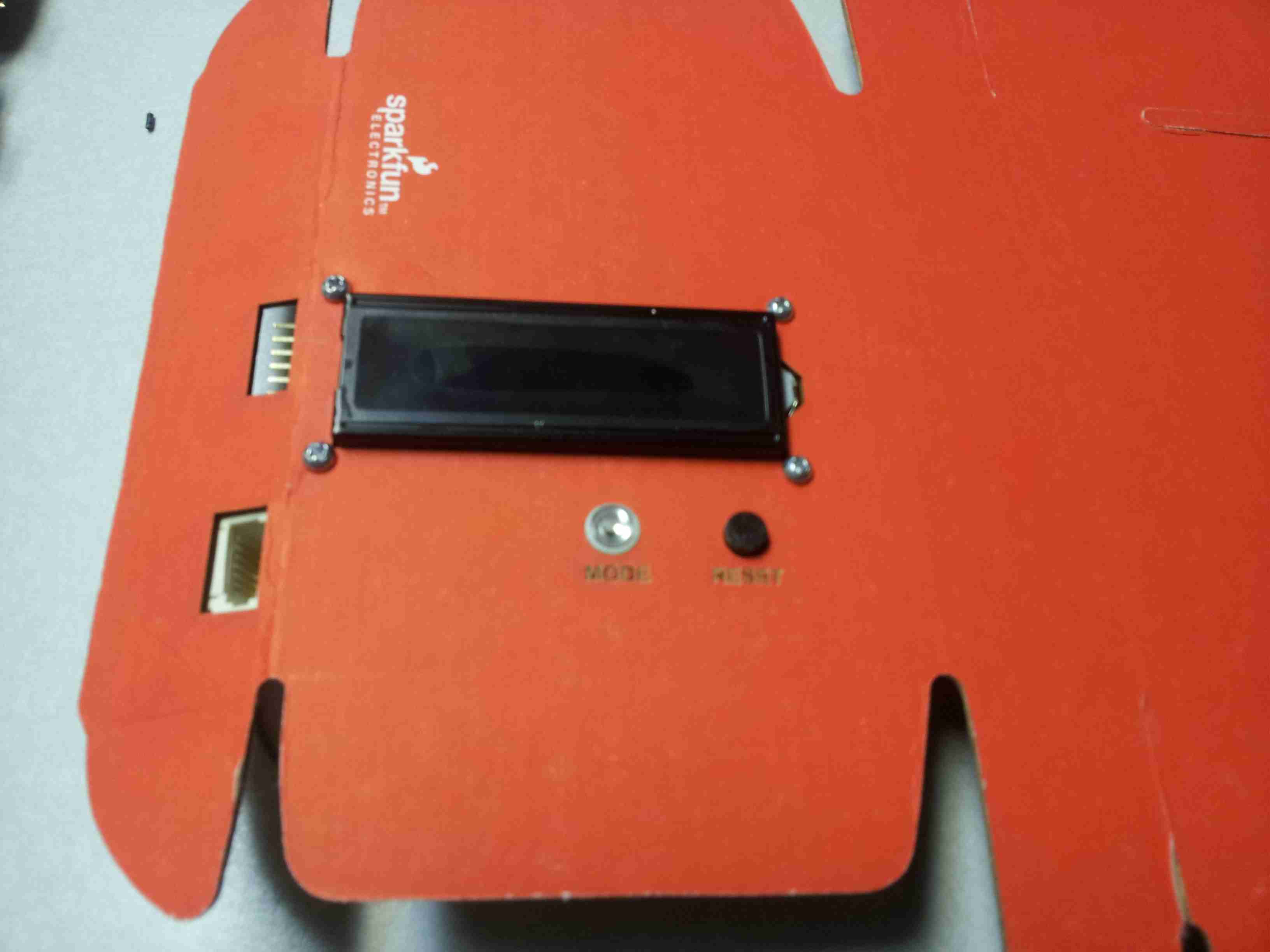
I made several measurements for the LCD. Links to the drawing files can be found below. I added a couple buttons for mode/select, reset, and I cut holes on the side to access the FTDI programming pins.
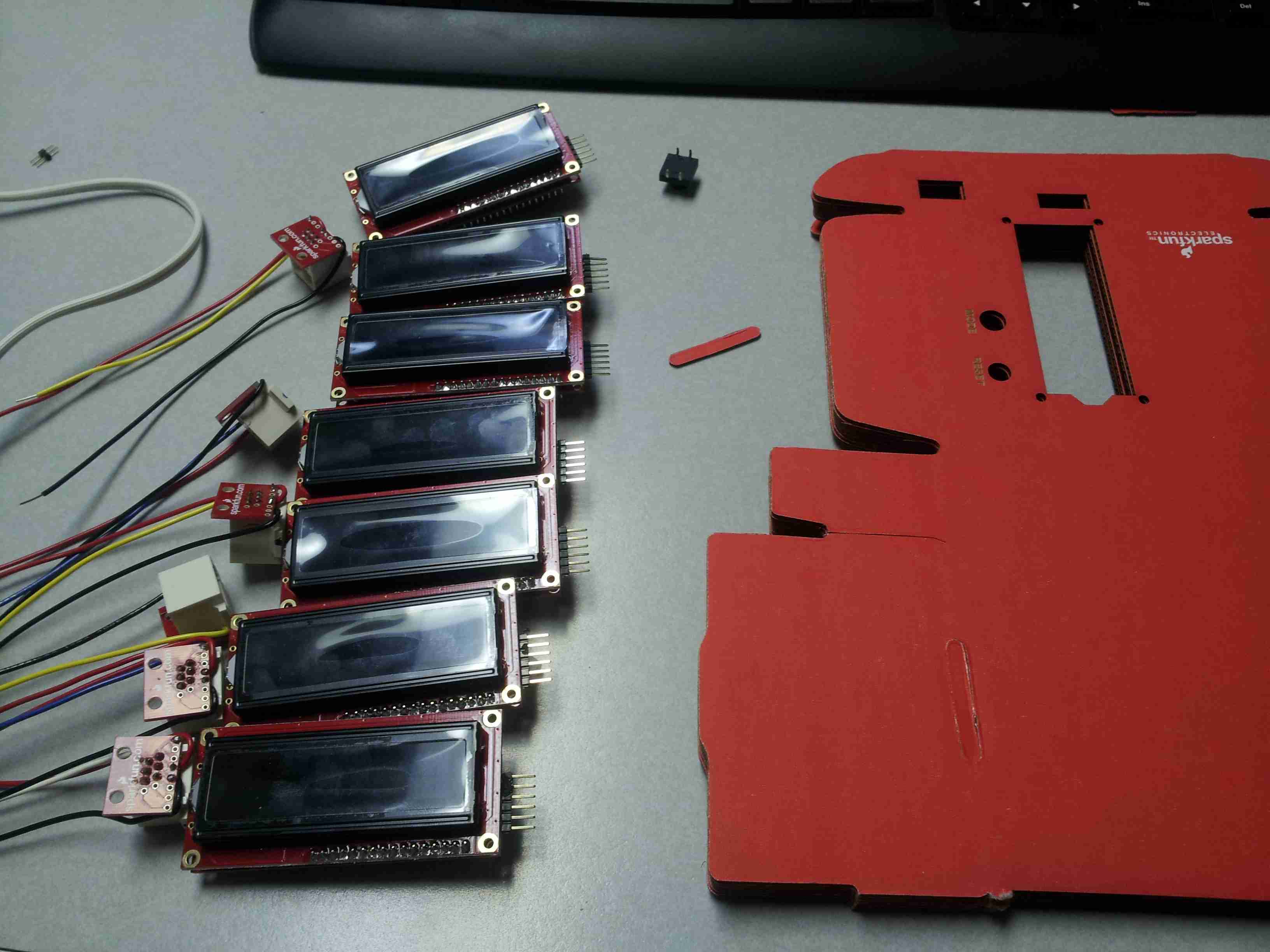
Cutting out the Case
The initial grant stipulated we build up 8 of these units to test. So, I set up an assembly line to do this.
I added an LED button for the MODE switch and a standard 12 mm push button for the RESET.
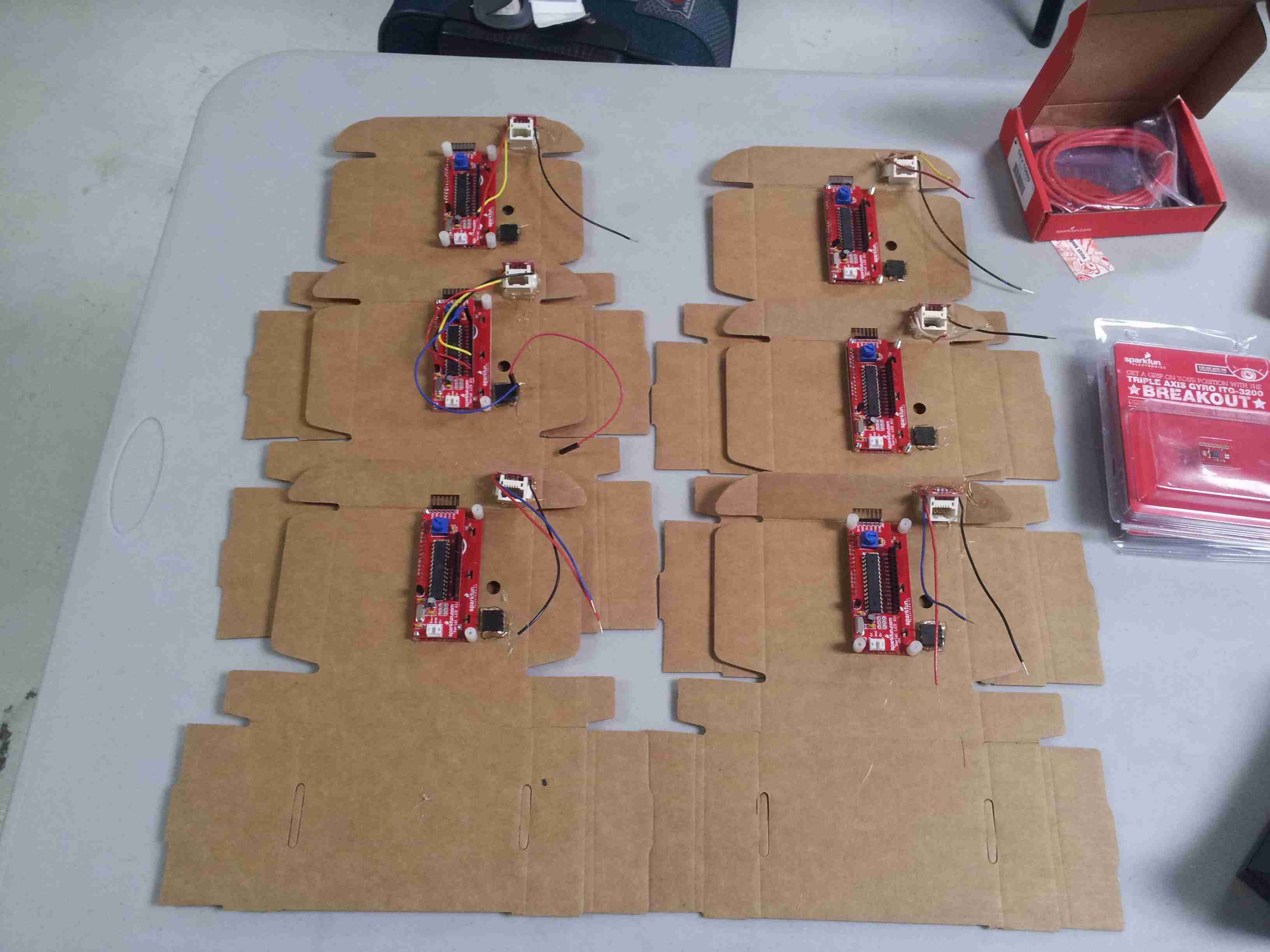
The Wiring
Using some standard 18 AWG hook-up wire I connected up the Vernier BTD Connector, two push buttons, and added a female barrel jack adaptor for power.
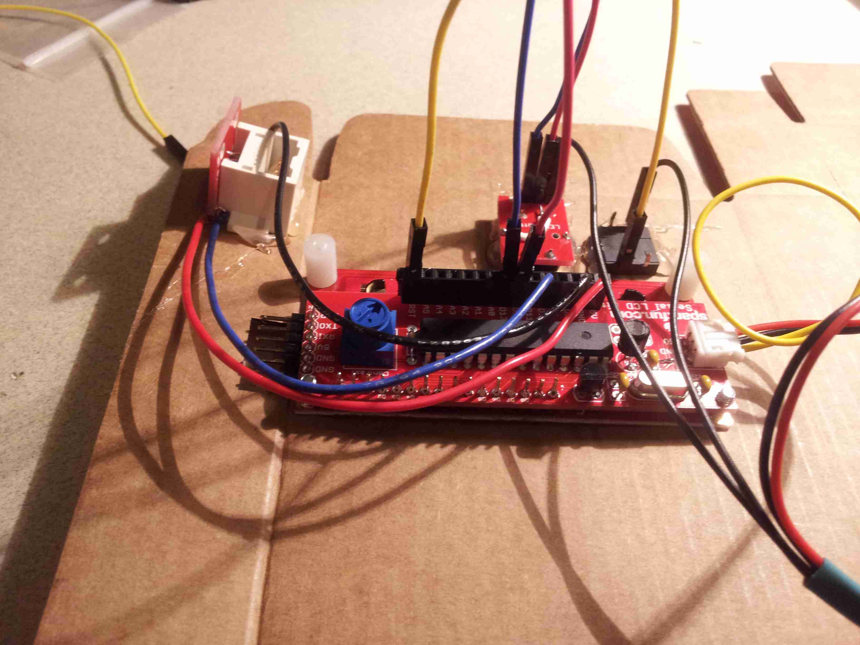
Since you probably can't tell where all of these wires are going, here is a simplified Fritzing diagram illustrating the connections.
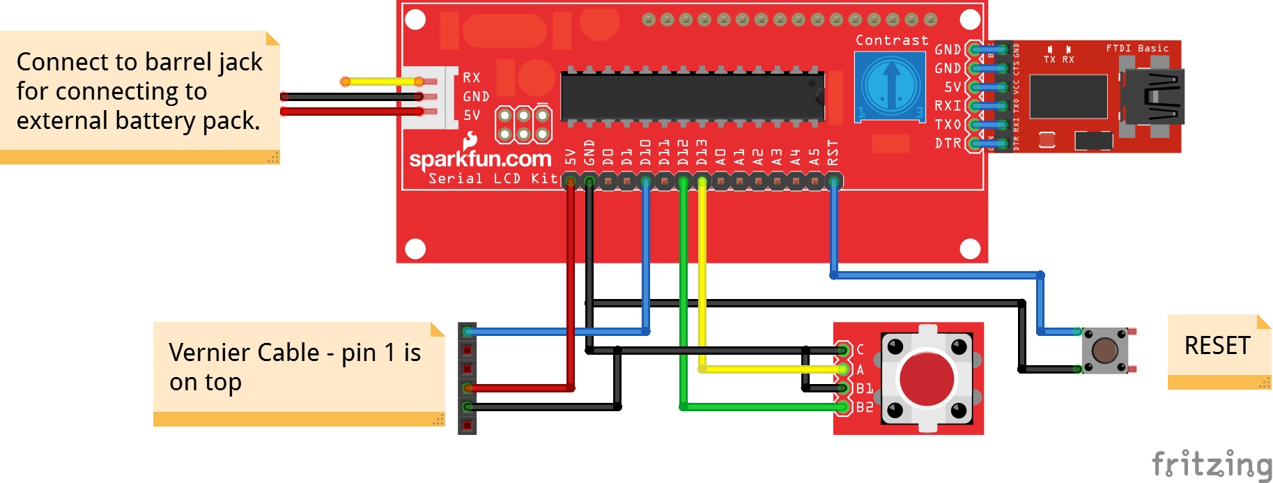
Click here for the Fritzing drawing.
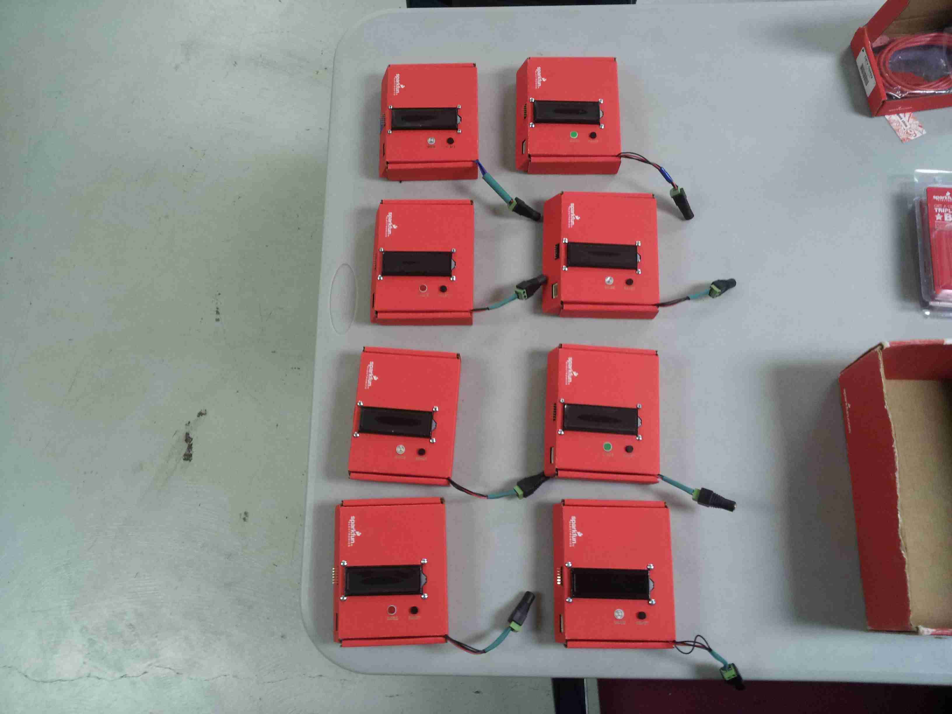
Assembly Complete
Here are the 8 fully assembled photogate timer units. Ready for programming.