Triple Axis Accelerometer Breakout - KX13x (Qwiic) Hookup Guide
Introduction
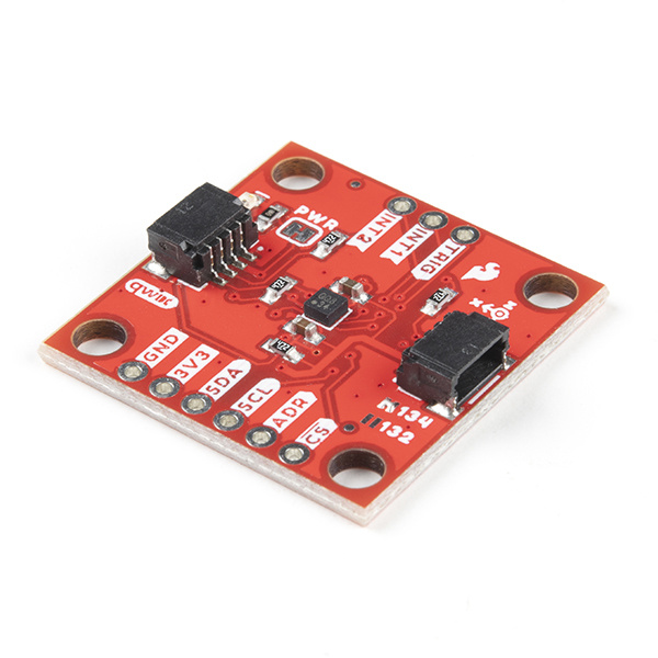
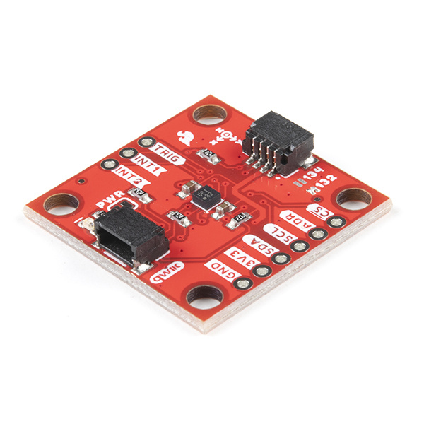
The SparkFun Triple Axis Accelerometer Breakout - KX134 (Qwiic) and Triple Axis Accelerometer Breakout - KX132 (Qwiic) offer two high-speed additions to SparkFun's accelerometer selection featuring the KX134-1211 and KX132-1211 3-axis digital accelerometers from Kionix. The KX134 and KX132 both include a host of accelerometer features including Freefall detection, Directional Tap™ and Double-Tap™ detection, tilt orientation detection and more. The breakouts can interface with controllers using both I2C and SPI at high speeds so you can use it in either an existing Qwiic/I2C chain or SPI bus.
The KX134 is a low-power, 16-bit resolution 3-axis accelerometer capable of measuring ±8g/16g/32g/64g (user selectable) and has up to a 10kHz (max) output data rate making it ideal for high-g measurements as well as high-speed applications such as vibration sensing. The KX132 offers nearly the same data specifications at smaller acceleration (±2g/4g/8g/16g) ranges. At lower ranges the sensitivity can be set as high as 17367 counts/g (@±2g), so it's a great for applications looking for both high-speed data rates and high-sensitivity measurements at lower acceleration ranges.
Required Materials
In order to follow along with this tutorial you'll need a few items along with your KX13x Breakout. First, you will need a microcontroller or single-board computer (SBC) like a Raspberry Pi to communicate with the board. Click the button below to toggle to recommended Raspberry Pi and Qwiic Pi products.
Raspberry Pi Materials (Toggle)
NVIDIA Jetson Nano 2GB Developer Kit
DEV-17244SparkFun DLI Kit for Jetson Nano 2GB
KIT-17245At least one Qwiic cable is recommended to connect your KX13x Breakout to your microcontroller/SBC:
Qwiic Cable - 100mm
PRT-14427Qwiic Cable - 200mm
PRT-14428Qwiic Cable - 500mm
PRT-14429For users who wish to communicate with the KX13x Breakout using SPI, some through-hole soldering will be necessary. You may already have a few of these items but if not the tools and products below will help with that assembly:
Suggested Reading
If you aren't familiar with the Qwiic system, we recommend reading here for an overview:
 |
We would also recommend taking a look at the following tutorials if you aren't familiar with the concepts covered in them:
Serial Peripheral Interface (SPI)
Logic Levels
I2C
Serial Terminal Basics
Hardware Overview
In this section we'll cover the unique aspects of the KX134 and KX132 accelerometers along with other components found on the Triple Axis Accelerometer Breakout - KX13x (Qwiic).
KX132 & KX134 3-Axis Accelerometers
First up let's examine the two accelerometers on the boards, highlight their specifications and how they differ. The KX134-1211 and KX132-1211 offer the following features:
- Four User-Selectable Measurement Ranges
- KX134: ±8 / 16 / 32 / 64g
- KX132: ±2 / 4 / 8 / 16g
- User-configurable 3-stage Advanced Data Path (ADP) with low-pass filter, low-pass/high-pass filter and RMS calculation engine
- User-selectable Low Power or High-Performance Modes
- Configurable Output Data Rate (ODR) up to 25,600Hz
- High resolution Wake-Up / Back-to-Sleep functions with configurable thresholds (as low as 15.6mg on the KX134 & 39mg on the KX132)
- Free fall detection
- Directional-Tap™/Double-Tap™
- Device Orientation algorithms
- Embedded 512-byte FIFO buffer (continues to record while being read)
- Digital I2C up to 3.4MHz and Digital SPI up to 10MHz
The KX13x also includes an integrated voltage regulator to maintain consistent performance across its entire supply voltage range (1.7 to 3.6V). The table below outlines some of the electrical and functional characteristics of the KX134-1211 and KX132-1211 from the sensors' datasheets. All values in the table apply to both accelerometers unless specifically noted in the table or notes below it. Refer to the accelerometers' datasheets for a full overview: KX132-1211 & KX134-1211.
| Parameter | Units | Min | Typical | Max | |
|---|---|---|---|---|---|
| Supply Voltage (VDD) | V | 1.7 | 2.5 (3.3 for use with Qwiic) | 3.6 | |
| Current Consumption (Accelerometer Only) | High Performance w/Wake-up Detection (ODR=800Hz) | µA | 148 | ||
| Low Power w/Wake-up Detection (ODR=0.781Hz, 2 samples averaged) | 0.53 | ||||
| Standby | 0.50 | ||||
| Operating Temperature Range | °C | -40 | - | 105 | |
| Output Data Rate | Hz | 0.781 | 50 | 25600 | |
| Sensitivity (16 bit) | ±2g[1] | counts/g | 14501 | 16384 | 17367 |
| ±4g[1] | 7700 | 8192 | 8684 | ±8g | 3768 | 4096 | 4424 |
| ±16g | 1884 | 2048 | 2212 | ||
| ±32g[2] | 942 | 1024 | 1106 | ||
| ±64g[2] | 471 | 512 | 553 | ||
| Noise[3] | RMS | mg | KX134: 1.9 | ||
| KX132: 0.7 | |||||
| Density | µg/√Hz | KX134: 300 | |||
| KX132: 150 | |||||
| I2C Address | 0x1E (0x1F alternate) | ||||
2. Reminder: ±32/64g ranges are only availabe on the KX134.
3. Acceleration data noise varies depending on ODR, power mode & Average Filter Control settings. Noise measuring settings: High-Performance Mode (RES=1), ODR=50Hz, IIR Filter Enabled and IIR filter corner frequency set to ODR/2. Refer to Table 1 in the sensors' Datasheets as well as the Technical Reference Manuals for more information.
Pinout
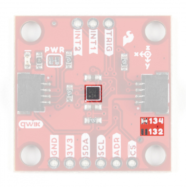
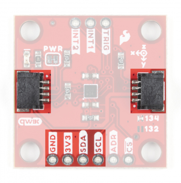
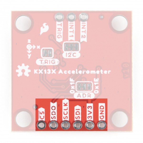
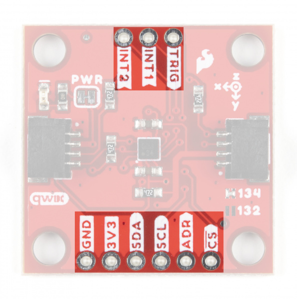
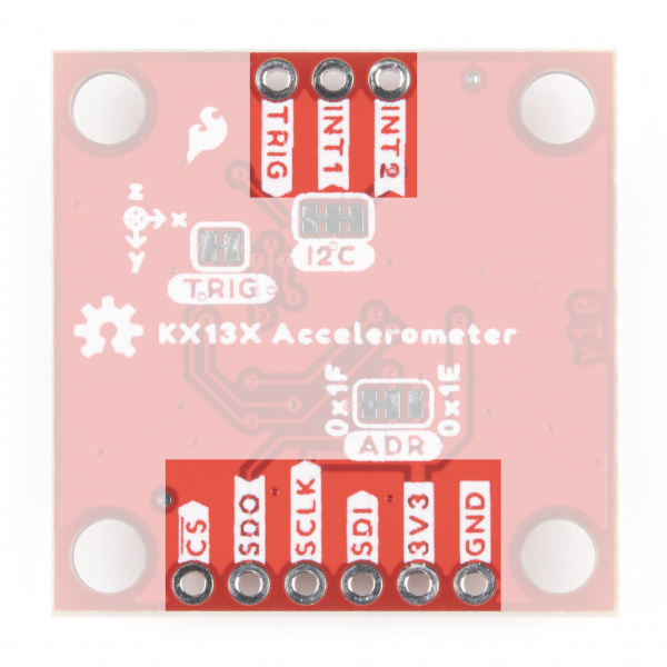
The KX13x Breakouts' I2C and SPI interface share the same pins so users must select the interface mode by altering the state of the ADR/SDO pin. The ADR jumper sets the state of the ADR/SDO pin (more on that in the Solder Jumpers section). Both breakouts operate in I2C mode by default. We've labeled these shared pins so I2C labels are visible from the front and SPI labels are visible when viewed from the back.
 |
 |
Qwiic and I2C Interface
As you would expect on a Qwiic breakout, the boards break out the KX134's I2C pins to a pair of Qwiic connectors to easily integrate the board into a Qwiic system. The I2C pins are also routed to a standard 0.1" spaced header for PTH soldering.
SPI Interface
Communicating via SPI on the Qwiic KX13x is ideal for taking advantage of the maximum Output Data Rate as the Digital SPI interface on the KX13x-1211 can operate at speeds up to 10MHz.
The Qwiic KX13x breaks out the SPI interface to the same standard 0.1" spaced header as the I2C pins. As mentioned above, the board ships with the I2C interface enabled by default so to switch to the SPI interface users need to open the ADR jumper by severing the trace in between the "Center" and "Left" pads and connect the SDO/ADR pin to SDI/CIPO on your microcontroller.
Interrupt and Trigger Pins
The KX13x has two physical interrupt pins as well as a trigger pin for FIFO buffer control. Both of the physical interrupts operate as push-pull, enter a high-impedence (high-Z) state during the Power-On-Reset (POR) procedure and are driven LOW after POR. Connect these pins to external interrupt-capable pins on your microcontroller to use the interrupt functionalities. Refer to the Interrupt and Buffer examples in the Qwiic KX13x Arduino and Python libraries for a demonstration of using the interrupt pins.
The Trigger pin controls the FIFO buffer. By default, the Qwiic KX13x ties this pin to ground through the TRIG jumper. Users who wish to use the Trigger pin must open that jumper before tying it to a pin on their microcontroller. Refer to the Datasheets (KX132 & KX134) and either Technical Reference Manuals (KX132 or KX134) for more information on using this pin to control the FIFO buffer.
Solder Jumpers
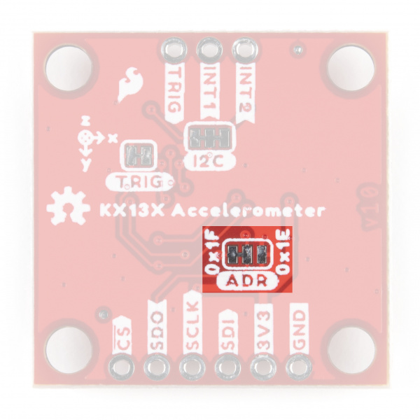
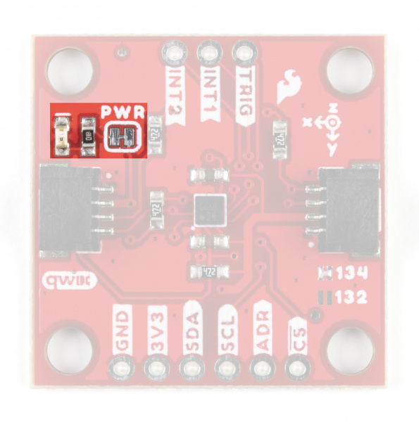
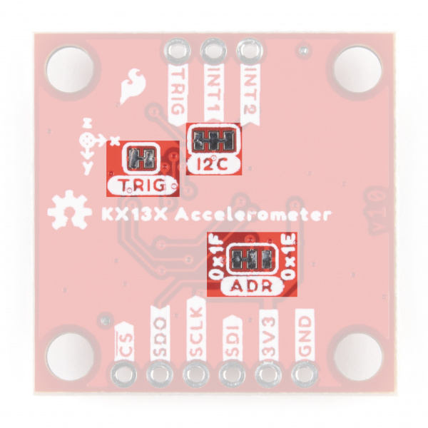
The Qwiic KX13x has four jumpers labeled ADR, I2C, TRIG and PWR. In this section we'll cover each jumper's purpose, their default states and how to configure them to alter the functionality of the KX13x Breakouts.
 |
 |
Address (ADR) Jumper
This 3-way jumper selects the I2C address of the KX13x and also selects the communication interface for the chip by pulling the ADR/SDO pin to either 3.3V, 0V/Ground or No Connect. By default, the ADR/SDO is pulled to 3.3V via a 4.7kΩ resistor to set the KX134 to operate in I2C mode with the I2C address as 0x1E.
To change the I2C address to 0x1F, sever the trace between the "Center" and "Left" pads and then connect the "Center" and "Right" pads together to pull the ADR/SDO pin to 0V/Ground.
Finally, to set the Qwiic KX13x to SPI mode, sever the trace between the "Center" and "Left" pads of the ADR jumper (default setting) to leave the ADR/SDO pin Floating/No Connect. After adjusting the jumper, connect the SDO pin to your controller's SDI/COPI pin.
I2C Jumper
The I2C jumper on the Qwiic KX13x pulls the SDA and SCL lines to 3.3V via a pair of 4.7kΩ resistors. The default state of this jumper is CLOSED. Open the jumper by severing the traces between the three pads to disable the pullups on these lines.
If you have more than one device on a single I2C bus, best practices recommend to only maintain a single pair of pullup resistors to avoid creating too strong of a parallel resistance. A strong parallel resistance can lead to communication issues on the bus. Take note that if you are using a single set of pull-up resistors on your I2C bus, make sure all devices operate at the same logic level or are properly shifted to avoid damage to the device(s).
Trigger (TRIG) Jumper
The Trigger jumper ties the TRIG pin on the KX13x-1211 to 0V/Ground. The default state of this jumper is CLOSED. To use the Trigger pin for FIFO control, open the jumper and connect the TRIG PTH pin to a digital I/O pin on your microcontroller. Refer to section 2.5 in the Technical Reference Manuals (KX132 or KX134) for more information on using Trigger Mode.
Power LED (PWR) Jumper
The Power LED jumper (labeled PWR on the board) completes the power LED circuit on the board by tying the anode of the LED to 3.3V via a 1kΩ resistor. The jumper is CLOSED by default. Disable the power LED by severing the trace between the two pads. Disabling the LED helps reduce the total current draw of the board and is particularly helpful for low-power or battery-powered applications.
Board Dimensions
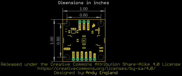
The Triple Axis Accelerometer Breakout - KX13x (Qwiic) matches the standard 1x1" (25.4mm x 25.4mm) dimensions for Qwiic breakouts and has four mounting holes that fit a 4-40 screw.
Hardware Assembly
Now that we're familiar with the KX13x and the other hardware present on the KX13x Breakouts we can start assembling our circuit. Depending on your preferred use of the accelerometer, you'll want to connect either using I2C using the Qwiic connector (or the PTH header) or via SPI using the PTH header on the board.
Qwiic/I2C Assembly
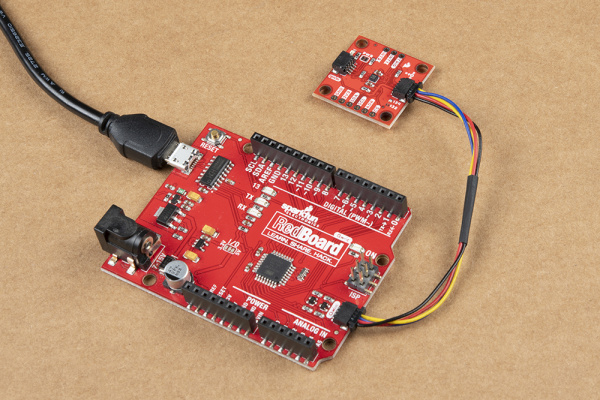
The fastest and easiest way to get started using the breakout is using either of the Qwiic connectors, a Qwiic cable and a Qwiic-enabled development board like the SparkFun RedBoard Qwiic. If you are using a Raspberry Pi instead for our Python Package, you'll need a Pi, Qwiic cable and an adapter like the Qwiic Shim or another of our Qwiic-enabled pHATs.
If you would prefer a more secure and permanent connection, you can solder headers or wire to the PTH header on the board. This method is recommended for permanent installations as well as high-g and vibration sensing applications.
SPI Assembly
If you'd prefer to take advantage of the max output data rate of the KX13x, you'll want to use the SPI interface instead of the I2C interface. Assembling the KX13x Breakout in SPI mode requires some through-hole soldering. If you are not familiar with through-hole soldering, take a read through this tutorial:
How to Solder: Through-Hole Soldering
Along with tools for soldering, you'll need either some hookup wire or headers and jumper wires. Also, the Address (ADR) Jumper must be opened by severing the trace between the "Center" and "Left" pads to switch to SPI mode. After opening this jumper, connect the SDO pin to your controller's SDI/CIPO pin.
With the KX13x Breakout set to SPI mode, solder headers or wire to the PTH header on the board and make the SPI connections with your controller. Remember the KX13x operates at 3.3V logic so make sure to connect to a board running at the same logic level or use a level shifter to adjust it to a safe voltage.
KX13x Arduino Library
The SparkFun KX13x Arudino library makes it easy to get started measuring acceleration data from the sensor. Install the library through the Arduino Library Manager by searching for "SparkFun KX13x Arduino Library". If you prefer manually downloading the library from the GitHub repository, you can grab it here:
Arduino Examples
The SparkFun Qwiic KX13x Arduino Library includes four examples to get started with both KX13x boards.
Example 1 - Basic Readings
Example 1 is a basic example to demonstrate how to read data from the accelerometer. Open the example by navigating to "File > Examples > SparkFun Qwiic KX13x Library > Example1BasicReadings". Next, open the Tools menu and select your board (in this case, Arduino Uno) and correct Port your board enumerated on. Upload the code, open the serial monitor and set the baud rate to 115200.
The example defaults to use the KX132 so if you are using the KX134, make sure to comment/uncomment the appropriate line:
language:c
SparkFun_KX132 kxAccel;
//SparkFun_KX134 kxAccel; // For the KX134, uncomment this and comment line above
The setup initializes the sensor and performs a software reset, configures it to operate at the 16g range and enable the accelerometer. Just as above, make sure to select the appropriate option for either the KX132/134 as the code defaults to the KX132.
language:c
if( !kxAccel.begin() )
    {
    Serial.println("Could not communicate with the the KX13X. Freezing.");
    while(1);
    }

    Serial.println("Ready.");

    if( kxAccel.softwareReset() )
        Serial.println("Reset.");

    //Give some time for the accelerometer to reset.
    //It needs two, but give it five for good measure.
    delay(5);

    // Many settings for KX13X can only be
    // applied when the accelerometer is powered down.
    // However there are many that can be changed "on-the-fly"
    // check datasheet for more info, or the comments in the
    // "...regs.h" file which specify which can be changed when.
    kxAccel.enableAccel(false);

  kxAccel.setRange(SFE_KX132_RANGE16G);         // 16g Range
  //kxAccel.setRange(SFE_KX134_RANGE16G);         // 16g for the KX134

    kxAccel.enableDataEngine();     // Enables the bit that indicates data is ready.
    // kxAccel.setOutputDataRate(); // Default is 50Hz
    kxAccel.enableAccel();


}
After initializing the IC, the code prints out data for all three axes every 20ms. The delay here is important as it should be 1/ODR (Output Data Rate) and the default setting is 50Hz.
language:c
void loop() {

  myData = kxAccel.getAccelData();
  Serial.print("X: ");
  Serial.print(myData.xData, 4);
  Serial.print("g ");
  Serial.print(" Y: ");
  Serial.print(myData.zData, 4);
  Serial.print("g ");
  Serial.print(" Z: ");
  Serial.print(myData.zData, 4);
  Serial.println("g ");

  delay(20); // Delay should be 1/ODR (Output Data Rate), default is 50Hz

}
Example 2 - Interrupts
Example 2 shows how to use the hardware interrupt pin(s) on the accelerometer. In order to use this example, connect the INT1 pin on the KX13x breakout to an interrupt-capable pin. This example assumes a SparkFun RedBoard Qwiic is used so adjust the code as necessary. To follow along with this example (as well as the Buffer Example), assemble your circuit with INT1 connected to 2 on your development board.
If you aren't sure which pins on your development are capable of external interrupts, this reference page has a list of available pins on common Arduino development boards.
Along with creating the KX13x and data objects, the code sets the physical interrupt pin as 2.
language:c
byte dataReadyPin = 2;
The code initializes the accelerometer and disables the accelerometer briefly to configure the interrupt settings for data ready on INT1:
language:c
kxAccel.enableDataEngine();             //  Enables the bit that indicates data is ready.
kxAccel.enablePhysInterrupt();          //  Enables interrupt pin 1
kxAccel.routeHardwareInterrupt(0x10);   //  Routes the data ready bit to pin 1
After initializing the sensor, the main loop monitors the dataReadyPin (D1) and if it is HIGH, prints out data for all three axes:
language:c
void loop() {

  if( digitalRead(dataReadyPin) == HIGH ){ // Wait for new data to be ready.

    myData = kxAccel.getAccelData();
    Serial.print("X: ");
    Serial.print(myData.xData, 4);
    Serial.print("g ");
    Serial.print(" Y: ");
    Serial.print(myData.zData, 4);
    Serial.print("g ");
    Serial.print(" Z: ");
    Serial.print(myData.zData, 4);
    Serial.println("g ");

     //kxAccel.clearInterrupt();// Because the data is being read in "burst"
     //mode, meaning that all the acceleration data is being read at once, we don't
     //need to clear the interrupt.
  }
  delay(20); // Delay should be 1/ODR (Output Data Rate), default is 50Hz
}
Example 3 - Buffer
The third example shows how to configure and use the KX13x buffer settings to trigger hardware interrupts when the buffer is full. Just like Example 2 , the code sets the physical interrupt/data ready pin as 2 which is driven HIGH when the buffer is full. Just like with Example 2, in order to use this example, connect the INT1 pin on the KX13x breakout to an interrupt-capable pin. This example assumes a SparkFun RedBoard Qwiic/Arduino Uno is used so adjust the code as necessary.:
language:c
byte dataReadyPin = 2;
The setup configures the KX13x to enable the buffer interrupt as a hardware interrupt in FIFO mode:
language:c
kxAccel.enableBufferInt();                          //  Enables the Buffer interrupt
kxAccel.enablePhysInterrupt();          //  Enables interrupt pin 1
kxAccel.routeHardwareInterrupt(0x40);   //  Routes the data ready bit to pin 1

kxAccel.enableSampleBuffer();                 // Enable buffer.
kxAccel.setBufferOperationMode(0x00); // Enable the buffer to be FIFO.
After setting everything up, the main loop waits for the buffer to fill and drive the data ready pin HIGH. Once the pin goes HIGH, the code prints out acceleration data for all three axes just like the other examples.
Qwiic KX13x Python Package
We've written a Python package to control the KX13x Breakouts for users who prefer a Raspberry Pi or other Python-specific development environment. You can install the sparkfun-qwiic-kx13x Python package hosted by PyPi through a command interface. If you prefer to manually download and build the libraries from the GitHub repository, you can download the package by clicking the button below:
(*Please be aware of any package dependencies. You can also check out the repository documentation page, hosted on Read the Docs.)
Installation
Note: Don't forget to double check that the hardware I2C connection is enabled on your Raspberry Pi or other single board computer. The Raspberry Pi tutorials linked in the note above cover how to enable the Pi's I2C bus.
PyPi Installation
This repository is hosted on PyPi as the sparkfun-qwiic-kx13x package. On systems that support PyPi installation via pip3 (use pip for Python 2) is simple using the following commands:
For all users (Note: the user must have sudo privileges):
language:bash
sudo pip3 install sparkfun-qwiic-kx13x
For the current user:
language:bash
pip3 install sparkfun-qwiic-kx13x
Local Installation
To install, make sure the setuptools package is installed on the system.
Direct installation at the command line (use python for Python 2):
language:bash
python3 setup.py install
To build a package for use with pip3:
language:bash
python3 setup.py sdist
A package file is built and placed in a subdirectory called dist. This package file can be installed using pip3.
language:bash
cd dist
pip3 install sparkfun_qwiic_kx13x-<version>.tar.gz
Qwiic KX13x Python Package Operation
For a full overview of all the functions included with the Qwiic KX13x Py package and how it works, take a look at the source code and package documentation hosted on ReadtheDocs page.
Upgrading the Python Package
If needed, the Python package can be upgraded using the following commands:
For all users (Note: the user must have sudo privileges):
language:bash
sudo pip3 install --upgrade sparkfun-qwiic-kx13x
For the current user:
language:bash
pip3 install --upgrade sparkfun-qwiic-kx13x
Python Examples
The Qwiic KX13X Python Package includes four examples to get users started with either Qwiic KX13x board using Python. In this section we'll go over the examples and highlight how they work.
To use the examples, open them from the Qwiic KX13X Py location or copy the code into your preferred Python interpreter.
Note, the examples default to using the Qwiic KX132 so if a Qwiic KX1334 is used, adjust the code by un-commenting this line:
language:python
myKX = qwiic_kx13x.QwiicKX134()
And replace any instance of kx132 with kx134. The acceleration range can also be adjusted by uncommenting this line and adjusting the value set for the range:
language:python
myKx.set_range(myKx.KX132_RANGE8G)
Example 1 - Simple Example
The first example is a basic example demonstrating how to initialize a Qwiic KX13x board on the I2C bus using its default settings. The full example code can be found below if you would prefer to copy it into your preferred Python interpreter:
language:python
from __future__ import print_function
import qwiic_kx13x
import time
import sys
import RPi.GPIO

def run_example():

    print("\nSparkFun KX13X Accelerometer Example 1\n")
    # myKx = qwiic_kx13x.QwiicKX134() # If using the KX134 un-comment this line and replace other instances of "kx132" with "kx134"
    myKx = qwiic_kx13x.QwiicKX132()

    if myKx.connected == False:
            print("The Qwiic KX13X Accelerometer device isn't connected to the system. Please check your connection", \
                    file=sys.stderr)
            return

    if myKx.begin():
        print("Ready.")
    else:
        print("Make sure you're using the KX132 and not the KX134")

    # myKx.set_range(myKx.KX132_RANGE8G) # Update the range of the data output.
    myKx.initialize(myKx.BASIC_SETTINGS) # Load basic settings

while True:

    myKx.get_accel_data()
    print("X: {0}g Y: {1}g Z: {2}g".format(myKx.kx132_accel.x,
                                           myKx.kx132_accel.y,
                                           myKx.kx132_accel.z))
    time.sleep(.02) #Set delay to 1/Output Data Rate which is by default 50Hz 1/50 = .02


if __name__ == '__main__':
        try:
            runExample()
        except (KeyboardInterrupt, SystemExit) as exErr:
            print("\nEnding Example 1")
            sys.exit(0)
Example 2 -
The second example shows how to enable Hardware Interrupt Pin 1 on the KX13x and fires it whenever data is ready. The complete example code can be found below if you prefer to copy/paste it into your prefered Python interpreter:
language:python
from __future__ import print_function
import qwiic_kx13x
import time
import sys
import RPi.GPIO

def runExample():

    print("\nSparkFun KX13X Accelerometer Example 1\n")
    # myKx = qwiic_kx13x.QwiicKX134() # If using the KX134 un-comment this line and replace other instances of "kx132" with "kx134"
    myKx = qwiic_kx13x.QwiicKX132()

    if myKx.connected == False:
        print("The Qwiic KX13X Accelerometer device isn't connected to the system. Please check your connection", \
                file=sys.stderr)
        return

    if myKx.begin():
        print("Ready.")
    else:
        print("Make sure you're using the KX132 and not the KX134")

    # myKx.set_range(myKx.KX132_RANGE8G) # Update the range of the data output.
    myKx.initialize(myKx.INT_SETTINGS) # Load basic settings

    dataReadyPin = 5
    GPIO.setmode(GPIO.BCM)
    GPIO.setup(dataReadyPin, GPIO.IN)

    while True:

        if GPIO.INPUT(dataReadyPin) == 1:

            myKx.get_accel_data()
            print("X: {0}g Y: {1}g Z: {2}g".format(myKx.kx132_accel.x,
                                                   myKx.kx132_accel.y,
                                                   myKx.kx132_accel.z))

        time.sleep(.02) #Set delay to 1/Output Data Rate which is by default 50Hz 1/50 = .02

if __name__ == '__main__':
    try:
        runExample()
    except (KeyboardInterrupt, SystemExit) as exErr:
        print("\nEnding Example 1")
        sys.exit(0)
Example 3 - Software Interrupts
Example 3 shows how to use software interrupts to signal when accelerometer data is ready. The primary difference between this and the hardware interrupts is none of the KX13x Hardware Interrupt Pins are enabled. The full example is below for users who prefer to copy/paste it into their Python interpreter:
language:python
from __future__ import print_function
import qwiic_kx13x
import time
import sys

def runExample():

    print("\nSparkFun KX13X Accelerometer Example 1\n")
    # myKx = qwiic_kx13x.QwiicKX134() # If using the KX134 un-comment this line and replace other instances of "kx132" with "kx134"
    myKx = qwiic_kx13x.QwiicKX132()

    if myKx.connected == False:
        print("The Qwiic KX13X Accelerometer device isn't connected to the system. Please check your connection", \
                file=sys.stderr)
        return

    if myKx.begin():
        print("Ready.")
    else:
        print("Make sure you're using the KX132 and not the KX134")

    # myKx.set_range(myKx.KX132_RANGE8G) # Update the range of the data output.
    myKx.initialize(myKx.SOFT_INT_SETTINGS) # Load basic settings

    while True:

        if myKx.data_trigger():

            myKx.get_accel_data()
            print("X: {0}g Y: {1}g Z: {2}g".format(myKx.kx132_accel.x,
                                                   myKx.kx132_accel.y,
                                                   myKx.kx132_accel.z))

        time.sleep(.02) #Set delay to 1/Output Data Rate which is by default 50Hz 1/50 = .02

if __name__ == '__main__':
    try:
        runExample()
    except (KeyboardInterrupt, SystemExit) as exErr:
        print("\nEnding Example 1")
        sys.exit(0)
Example 4 - Buffer Interrupt
The fourth and final example builds on the hardware interrupt example and uses the Hardware Interrupt Pins to indicate when a buffer is full and ready to be read. Copy/paste the code below into your preferred Python interpreter:
language:python
from __future__ import print_function
import qwiic_kx13x
import time
import sys
import RPi.GPIO

def runExample():

    print("\nSparkFun KX13X Accelerometer Example 1\n")
    # myKx = qwiic_kx13x.QwiicKX134() # If using the KX134 un-comment this line and replace other instances of "kx132" with "kx134"
    myKx = qwiic_kx13x.QwiicKX132()

    if myKx.connected == False:
        print("The Qwiic KX13X Accelerometer device isn't connected to the system. Please check your connection", \
                file=sys.stderr)
        return

    if myKx.begin():
        print("Ready.")
    else:
        print("Make sure you're using the KX132 and not the KX134")

    # myKx.set_range(myKx.KX132_RANGE8G) # Update the range of the data output.
    myKx.initialize(myKx.BUFFER_SETTINGS) # Load basic settings

    dataReadyPin = 5
    GPIO.setmode(GPIO.BCM)
    GPIO.setup(dataReadyPin, GPIO.IN)

    while True:

        if GPIO.INPUT(dataReadyPin) == 1: # When the buffer is full, the pin will go high

            myKx.get_accel_data()
            print("X: {0}g Y: {1}g Z: {2}g".format(myKx.kx132_accel.x,
                                                   myKx.kx132_accel.y,
                                                   myKx.kx132_accel.z))

        time.sleep(.02) #Set delay to 1/Output Data Rate which is by default 50Hz 1/50 = .02

if __name__ == '__main__':
    try:
        runExample()
    except (KeyboardInterrupt, SystemExit) as exErr:
        print("\nEnding Example 1")
        sys.exit(0)
Troubleshooting
Switching to SPI
As we've covered before in this tutorial, using either KX13x Breakout in SPI mode requires a slight modification to the board. The ADR Jumper must be completely opened so the ADR/SDO pin is floating prior to being connected to the SPI controller's SDI/COPI pin. Also, make sure the controller the KX13x Breakout connects to runs at 3.3V logic to avoid damaging the IC. Using either accelerometer breakout with a 5V controller requires level shifting the signal.
General Troubleshooting and Technical Support
If you need technical assistance and more information on a product that is not working as you expected, we recommend heading on over to the SparkFun Technical Assistance page for some initial troubleshooting.
If you don't find what you need there, the SparkFun Forums are a great place to find and ask for help. If this is your first visit, you'll need to create a Forum Account to search product forums and post questions.
Resources and Going Further
For more information on the SparkFun Triple Axis Accelerometer Breakout - KX13x (Qwiic), take a look at the following recources:
- Schematic (PDF)
- Eagle Files (ZIP)
- KX134 Datasheet (PDF)
- KX132 Datasheet (PDF)
- KX134 Technical Reference Manual (PDF)
- KX132 Technical Reference Manual (PDF)
- AN092 Getting Started App Note (PDF)
- Hardware GitHub Repository
- Qwiic KX13x Arduino Library
- Qwiic KX13x Python Package
- Qwiic Landing Page
For some inspiration on motion-based projects using your KX13x Breakout, take a look at these tutorials:
