TMP102 Digital Temperature Sensor Hookup Guide
 Alex the Giant
 Introduction
The TMP102 is an easy-to-use digital temperature sensor from Texas Instruments. While some temperature sensors use an analog voltage to represent the temperature, the TMP102 uses the I2C bus of the Arduino to communicate the temperature.
Required Materials
To follow along with this hookup guide, you will need the following:
Suggested Reading
Before getting started, you may find the following links useful:
Pull-up Resistors
Installing an Arduino Library
How to Use a Breadboard
Logic Levels
I2C
Temperature Sensor Comparison
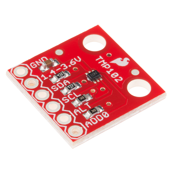
Board Overview
Let's go over the TMP102 Breakout in detail.
TMP102 Details:
- Uses the I2C interface
- 12-bit, 0.0625°C resolution
- Typical temperature accuracy of ±0.5°C
- Supports up to four TMP102 sensors on the I2C bus at a time
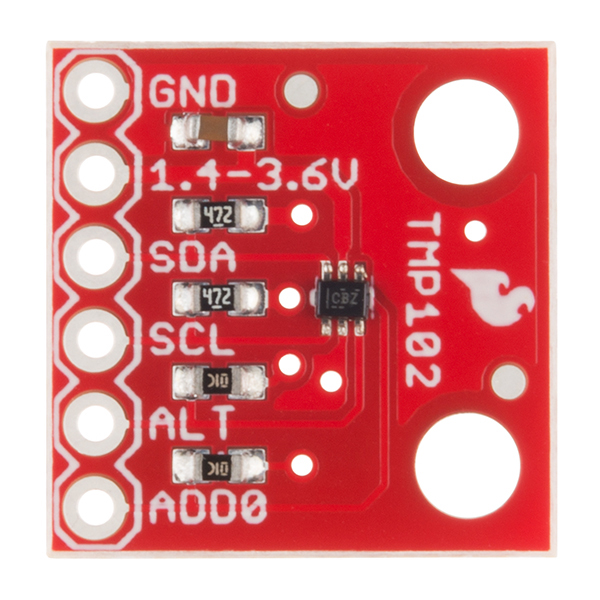
Pull-up Resistors
This breakout board has built-in 4.7 kΩ pull up resistors for I2C communications. If you're hooking up multiple I2C devices on the same bus, you may want to disable/enable the pull-up resistors for one or more boards. On the TMP102, the pull-ups are enabled by default. To disable them, simply use a hobby knife to cut the traces connecting the left and right pads of the jumper labeled I2C PU on the back of the board. This will disconnect the resistors from VCC and from the I2C bus.
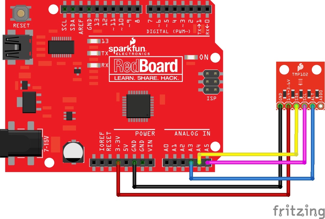
Hardware Connections
Connecting the TMP102 to an Arduino
Wiring the TMP102 is very easy! We recommend soldering six male headers to the breakout board. You can also solder wires to fit your application's needs.
Power
This board runs from 1.4V to 3.6V. Be sure to power the board from the 3.3V pin! I2C uses an open drain signaling, so there is no need to use level shifting; the 3.3V signal will work to communicate with the Arduino and will not exceed the maximum voltage rating of the pins on the TMP102.
Connections to the Arduino
The TMP102 breakout board has six pins, however we'll only be using five of the pins in today's example. We'll be connecting VCC and GND to the normal power pins, two data lines for I2C communication, and one digital pin to see if there is an alert. If you're using a newer board that has SDA and SCL broken out, you can connect the SDA and SCL pins directly to those pins. If you're using an older board, SDA and SCL are pins A4 and A5 respectively.
- VCC → 3.3V
- GND → GND
- SDA → SDA/A4
- SCL → SCL/A5
- ALT → A3
This would looks something like this:
The only pin that we aren't using is ADD0, this pin is used to change the address of the TMP102. If you're using multiple TMP102s or another device that uses that address, you'll want to use this pin to change the address. The default address is 0x48. You can change the address by cutting the ADD0 jumper on the back of the board and connecting an external jumper wire to the following pins:
- VCC → 0x49
- SDA → 0x4A
- SCL → 0x4B
TMP102 Library and Example Code
SparkFun has written a library to work with the TMP102. You can obtain this library through the Arduino Library Manager by searching for SparkFun TMP102. If you prefer downloading libraries manually, you can grab it from the GitHub Repository.
Once the library is installed, open Arduino, and expand the examples menu. You should see the TMP102 example.

TMP102 Library Overview
Main functions
These are functions used to read settings and temperatures from the sensor.
bool begin( uint8_t deviceAddress, TwoWire &wirePort ) - Takes the device address and I2C bus as optional inputs. If left blank, this function uses the default address 0x48, and uses the Wire bus.
float readTempC( void ) - Returns the current temperature in Celsius.
float readTempF( void ) - Returns the current temperature in Fahrenheit.
float readLowTempC( void ) - Reads T_LOW register in Celsius.
float readHighTempC( void ) - Reads T_HIGH register in Celsius.
float readLowTempF( void ) - Reads T_LOW register in Fahrenheit.
float readHighTempC( void ) - Reads T_HIGH register in Fahrenheit.
void sleep( void ) - Put TMP102 in low power mode (<0.5 uA).
void wakeup( void ) - Return to normal power mode (~10 uA). When the sensor powers up, it is automatically running in normal power mode, and only needs to be used after sleep() is used.
bool alert( void ) - Returns the state of the Alert register. The state of the register is the same as the alert pin.
void setLowTempC(float temperature) - Sets T_LOW (in Celsius) alert threshold.
void setHighTempC(float temperature) - Sets T_HIGH (in Celsius) alert threshold.
void setLowTempF(float temperature) - Sets T_LOW (in Fahrenheit) alert threshold.
void setHighTempF(float temperature) - Sets T_HIGH (in Fahrenheit) alert threshold.
void setConversionRate(uint8_t rate) - Sets the temperature reading conversion rate. 0: 0.25Hz, 1: 1Hz, 2: 4Hz (default), 3: 8Hz.
void setExtendedMode(bool mode) - Enable or disable extended mode. 0: disabled (-55C to +128C), 1: enabled (-55C to +150C).
void setAlertPolarity(bool polarity) - Sets the polarity of the alert. 0: active LOW, 1: active HIGH
void setFault(uint8_t faultSetting) - Sets the number of consecutive faults before triggering alert. 0: 1 fault, 1: 2 faults, 2: 4 faults, 3: 6 faults.
void setAlertMode(bool mode) - Sets the type of alert. 0: Comparator Mode (Active from when temperature > T_HIGH until temperature < T_LOW), 1: Thermostat mode (Active from when temperature > T_HIGH until any read operation occurs.
Example Code
Once the library is installed, open the example code to get started! Make sure to select your board and COM port before hitting upload to begin experimenting with the temperature sensor.
language:c
/******************************************************************************
TMP102_example.ino
Example for the TMP102 I2C Temperature Sensor
Alex Wende @ SparkFun Electronics
April 29th 2016
~

This sketch configures the TMP102 temperature sensor and prints the
temperature and alert state (both from the physical pin, as well as by
reading from the configuration register.

Resources:
Wire.h (included with Arduino IDE)
SparkFunTMP102.h

Development environment specifics:
Arduino 1.0+

This code is beerware; if you see me (or any other SparkFun employee) at
the local, and you've found our code helpful, please buy us a round!

Distributed as-is; no warranty is given.
******************************************************************************/

// Include the SparkFun TMP102 library.
// Click here to get the library: http://librarymanager/All#SparkFun_TMP102

#include <Wire.h> // Used to establied serial communication on the I2C bus
#include <SparkFunTMP102.h> // Used to send and recieve specific information from our sensor

// Connections
// VCC = 3.3V
// GND = GND
// SDA = A4
// SCL = A5
const int ALERT_PIN = A3;

TMP102 sensor0;

void setup() {
  Serial.begin(115200);
  Wire.begin(); //Join I2C Bus

  pinMode(ALERT_PIN,INPUT);  // Declare alertPin as an input

  /* The TMP102 uses the default settings with the address 0x48 using Wire.

     Optionally, if the address jumpers are modified, or using a different I2C bus,
     these parameters can be changed here. E.g. sensor0.begin(0x49,Wire1)

     It will return true on success or false on failure to communicate. */
  if(!sensor0.begin())
  {
    Serial.println("Cannot connect to TMP102.");
    Serial.println("Is the board connected? Is the device ID correct?");
    while(1);
  }

  Serial.println("Connected to TMP102!");
  delay(100);

  // Initialize sensor0 settings
  // These settings are saved in the sensor, even if it loses power

  // set the number of consecutive faults before triggering alarm.
  // 0-3: 0:1 fault, 1:2 faults, 2:4 faults, 3:6 faults.
  sensor0.setFault(0);  // Trigger alarm immediately

  // set the polarity of the Alarm. (0:Active LOW, 1:Active HIGH).
  sensor0.setAlertPolarity(1); // Active HIGH

  // set the sensor in Comparator Mode (0) or Interrupt Mode (1).
  sensor0.setAlertMode(0); // Comparator Mode.

  // set the Conversion Rate (how quickly the sensor gets a new reading)
  //0-3: 0:0.25Hz, 1:1Hz, 2:4Hz, 3:8Hz
  sensor0.setConversionRate(2);

  //set Extended Mode.
  //0:12-bit Temperature(-55C to +128C) 1:13-bit Temperature(-55C to +150C)
  sensor0.setExtendedMode(0);

  //set T_HIGH, the upper limit to trigger the alert on
  sensor0.setHighTempF(82.0);  // set T_HIGH in F
  //sensor0.setHighTempC(29.4); // set T_HIGH in C

  //set T_LOW, the lower limit to shut turn off the alert
  sensor0.setLowTempF(81.0);  // set T_LOW in F
  //sensor0.setLowTempC(26.67); // set T_LOW in C
}

void loop()
{
  float temperature;
  boolean alertPinState, alertRegisterState;

  // Turn sensor on to start temperature measurement.
  // Current consumtion typically ~10uA.
  sensor0.wakeup();

  // read temperature data
  temperature = sensor0.readTempF();
  //temperature = sensor0.readTempC();

  // Check for Alert
  alertPinState = digitalRead(ALERT_PIN); // read the Alert from pin
  alertRegisterState = sensor0.alert();   // read the Alert from register

  // Place sensor in sleep mode to save power.
  // Current consumtion typically <0.5uA.
  sensor0.sleep();

  // Print temperature and alarm state
  Serial.print("Temperature: ");
  Serial.print(temperature);

  Serial.print("\tAlert Pin: ");
  Serial.print(alertPinState);

  Serial.print("\tAlert Register: ");
  Serial.println(alertRegisterState);

  delay(1000);  // Wait 1000ms
}
Resources and Going Further
For more information about the TMP102 Breakout, check out the links below.
- Datasheet (PDF)
- Schematic (PDF)
- Eagle Files (ZIP)
- Arduino Library
- Github repo containing the latest and greatest files and code.
Looking for a faster way to connect? Try taking a look at the Qwiic version of the TMP102!
SparkFun Qwiic Digital Temperature Sensor - TMP102 Hookup Guide
For more sensor fun, check out these other great SparkFun tutorials.