The ClockClock Project
Introduction
What time is it?! It's time for an awesome Alchitry project, that's what! In this tutorial I’m going to walk you through how I built a ClockClock using the Alchitry Au to control all the motors.
What is a ClockClock? It is simply a clock made of clocks! The idea is to use many analog style clocks together to form the digits of the time. So meta.
First, let me start by saying this wasn’t my original idea. I came across this concept a few years ago and always thought it would be a great demo FPGA project since it requires so many control signals. The original clock can be found here.
There are a couple reasons this project makes such a great FPGA demo project. First, the clock requires 48 stepper motors. There are 24 “clocks” and each one has two independent hands. Using a standard step/direction stepper driver means you need two control signals per motor or 96 outputs. I wanted to be able to disable the drivers when the clock was stationary to save power. This added four more outputs (one for each “digit” of the clock). I also wanted to use an Arduino to generate the animations as it would be much easier to do this in code than hardware. To talk to the Arduino, I decided to use I2C over the Alchitry Au’s Qwiic connector. This required two more IO pins for a total of 102. Conveniently, the Alchitry Au has exactly 102 IO pins.
Besides showing off the massive amount of IO FPGAs are capable of, this project uses the Qwiic connector on the FPGA in a semi-unconventional way. The FPGA in this project acts as a peripheral instead of as a controller. The Arduino is the controller and issues all the commands to the FPGA. I actually think this will be a useful paradigm for many projects.
Some tasks are very simple in software but incredibly complicated in hardware. The opposite is also true. By linking a microcontroller and FPGA together you get the best of both worlds. The Qwiic connector on both boards makes this easy.
Required Materials
To follow along with this tutorial, you will need the following materials. You may not need everything though depending on what you have. Add it to your cart, read through the guide, and adjust the cart as necessary.
Tools
While there are quite a few ways to machine parts for this project, here are the tools we used:
- 3D Printer
- Shapeoko XXL
You Will Also Need
- 48x Valve Gear Stepper Motor
- 48x StepStick Stepper Motor Diver Module with Heat Sink
- 1x UBEC Adjustable BEC UBEC 2-6S for Quadcopter RC Drone
- 1x Enclosed AC-DC Switching Power Supply
Suggested Reading
If you aren't familiar with the Qwiic system, we recommend reading here for an overview.
| Qwiic Connect System |
We also recommend checking out these tutorials before continuing.
Programming an FPGA
How Does an FPGA Work?
First FPGA Project - Getting Fancy with PWM
Physical Build
In this section I’m going to be fairly brief as the focus of this tutorial is on FPGA designs and not woodworking.
Click on each of the links below to access and download the project files:
The project first started with trying to figure out how to make one of the clock movements. I needed two stepper motors and a way to connect them to two concentric output shafts.
Originally, I found these super tiny stepper motors on Amazon that measured a tiny 8 x 9.2mm! I designed a piece that had two big gears and two small gears that would press fit onto the motors.
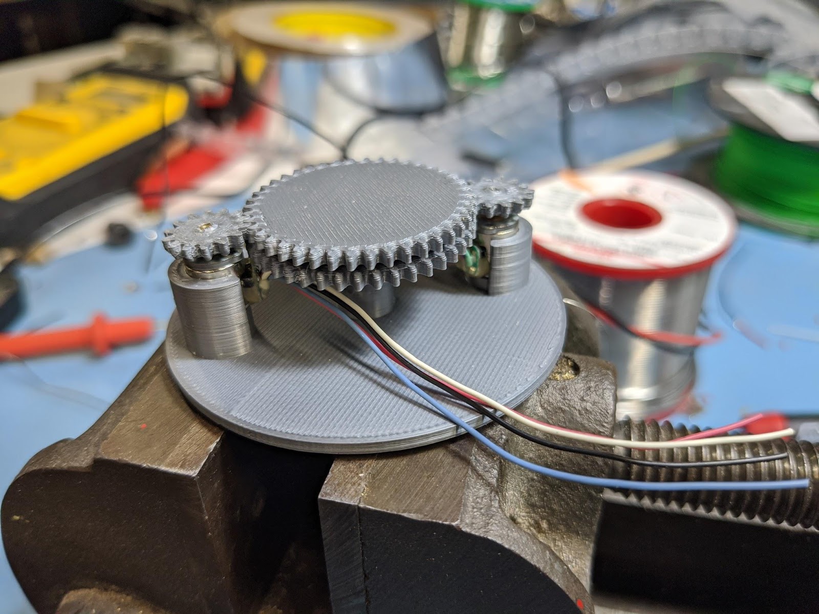
Unfortunately, these little motors just weren’t up for the task of turning the gears. They output only the smallest amount of torque and trying to drive them hard enough to work made them heat up to the point of them melting the 3D printed PLA parts.
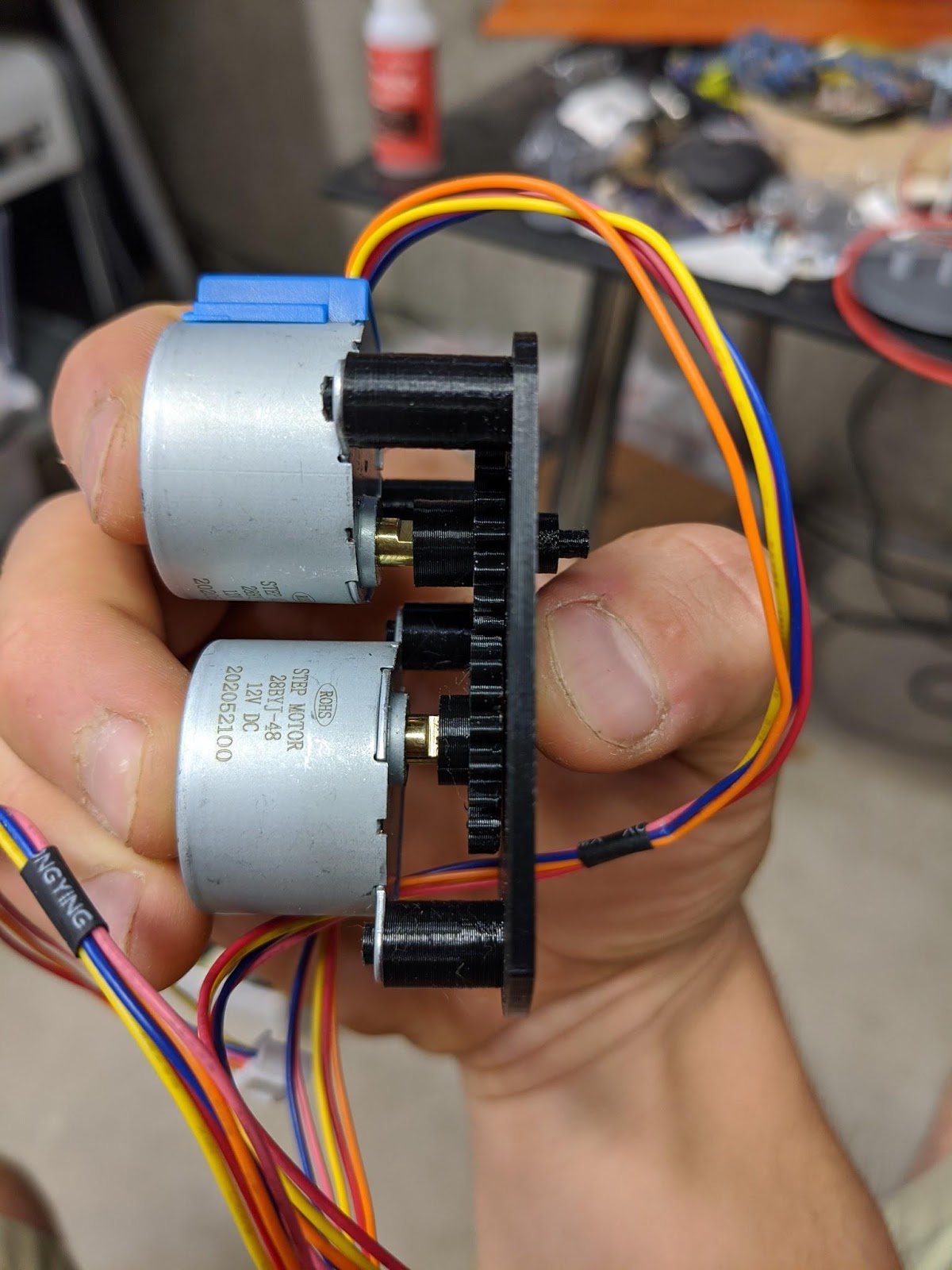
Giving up on these, I ordered a bunch of 28BYJ-48 stepper motors. These are quite a bit bigger but still plenty small for the clock. They also are internally geared and output plenty of torque. The internal gearing also means they have enough internal resistance to easily keep their position when powered off.
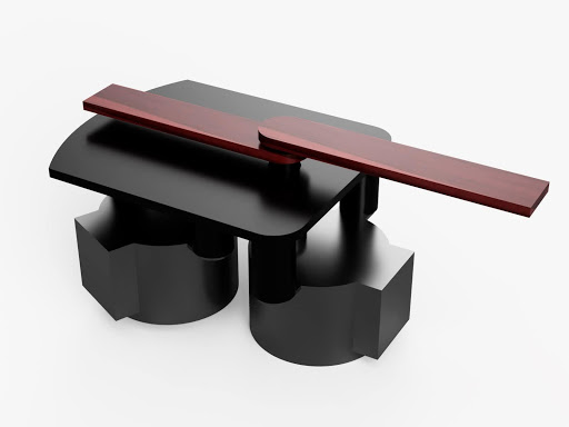
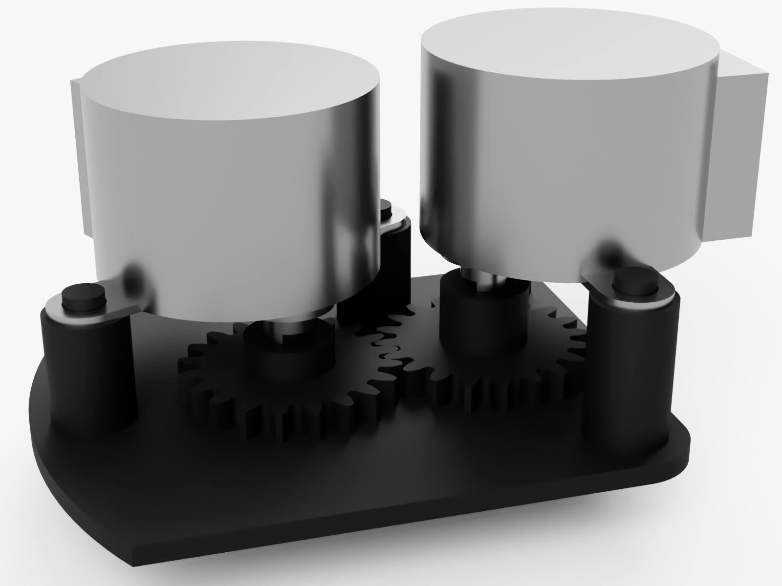
I designed a movement where the minute hand would be directly driven off the motor shaft and the hour hand would be driven via a gear so the motor could be offset to the side.
Here are some renders of the design. This first render shows the two output shafts. The center longer shaft connects directly to the motor inline with it. The outer shaft is attached to the gear and that gear is driven by the second motor. The hour and minute hands are friction fit onto these two shafts.

The friction fit allows the hands to be repositioned into a neutral position before the clock is powered on. This is important because even though stepper motors are great for controlling precise positions, they have no way of knowing where they start.
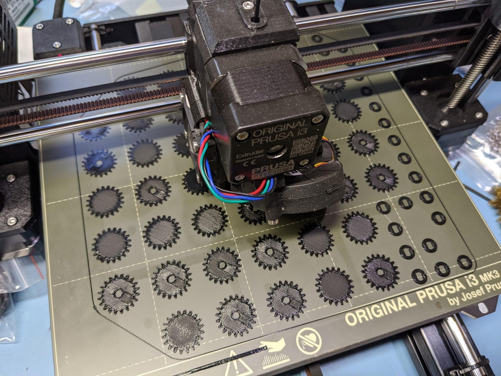
The motors were simply super glued onto the mounting pegs. All the parts were printed on my Prusa MK3S in black PLA.
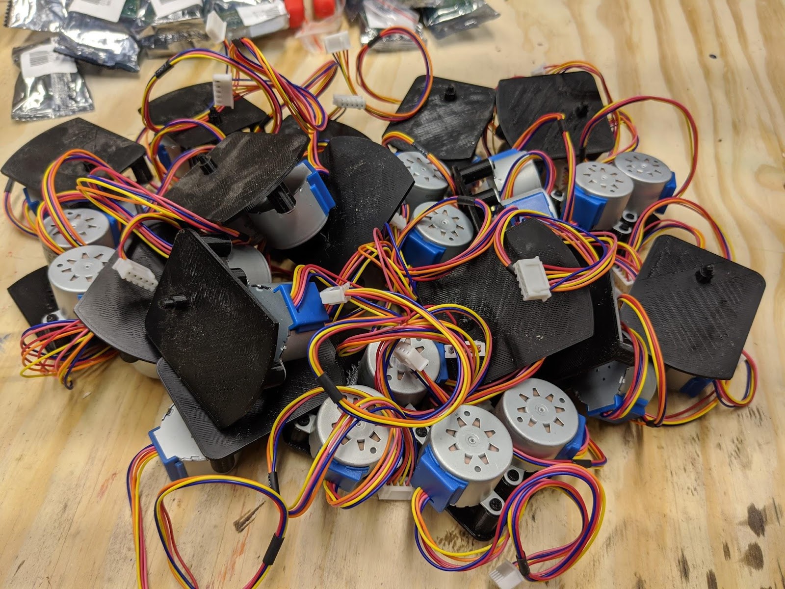
This is a photo of the first finalized movement I printed and assembled.
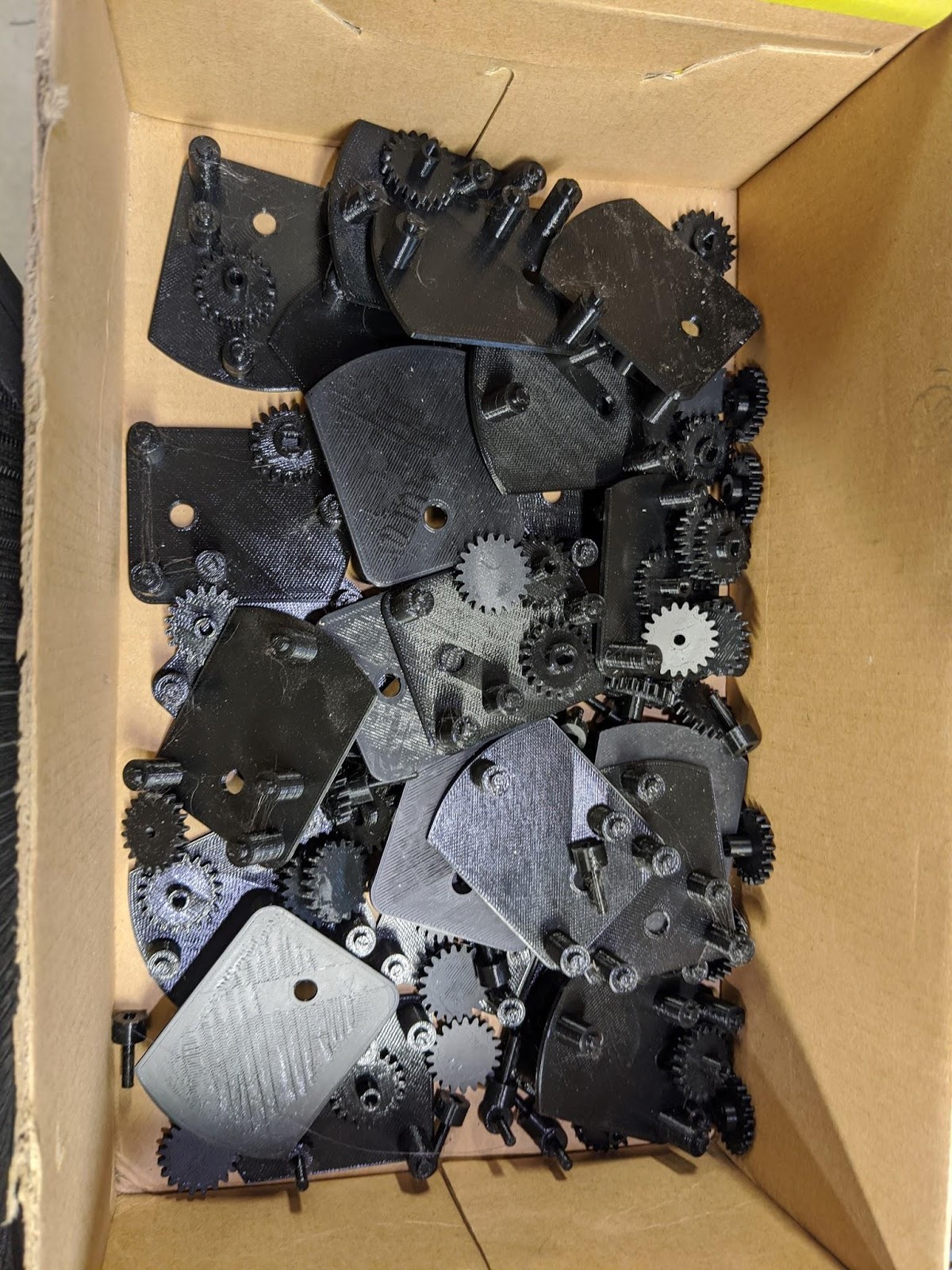
Once I had a working design, I was able to batch out the 24 of these I needed.
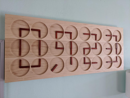
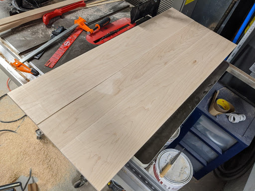
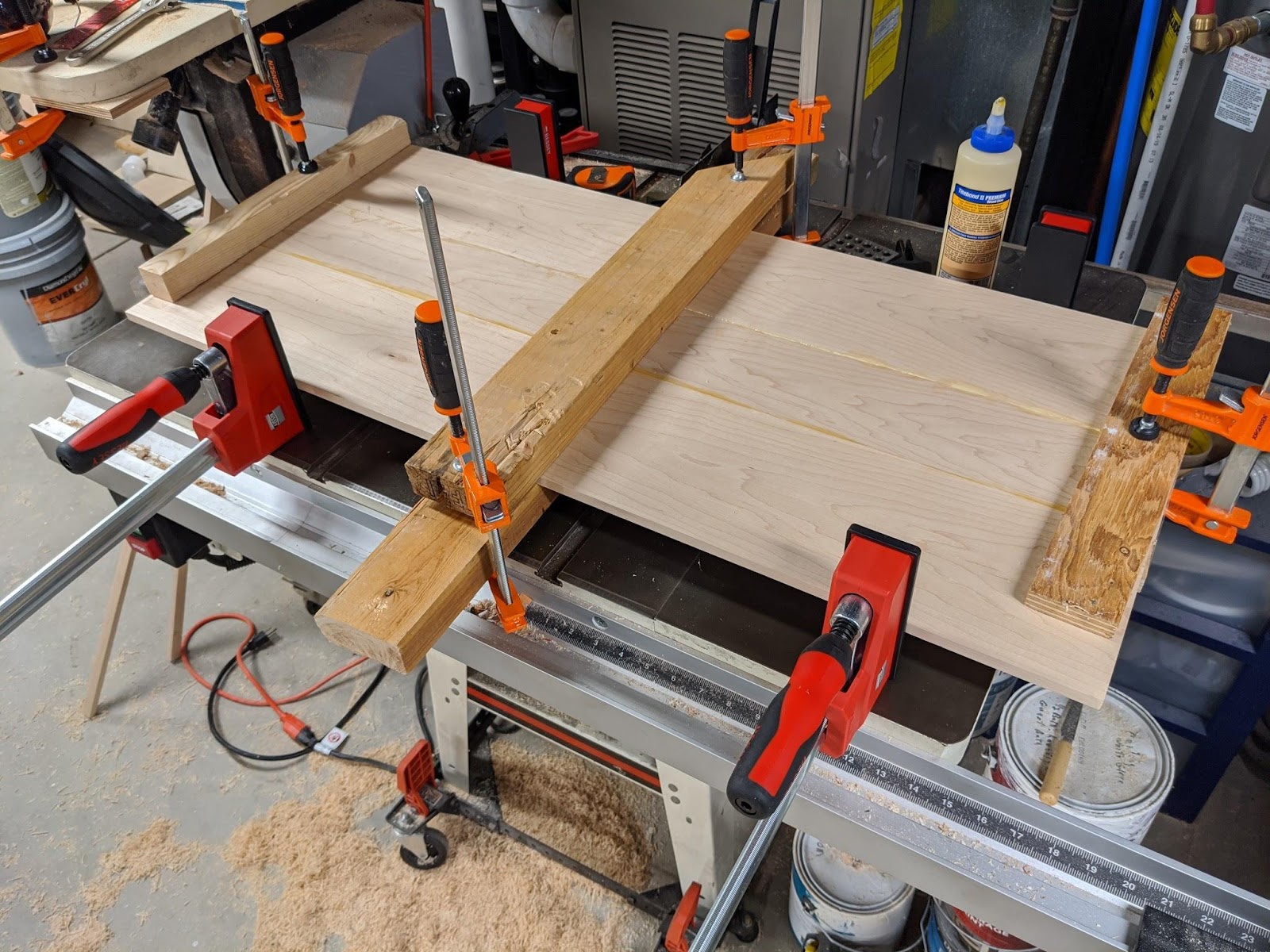
The next step was to create the frame. I made it out of two planks of maple. The first plank I resawed into three thinner pieces that I could glue together to make the face.
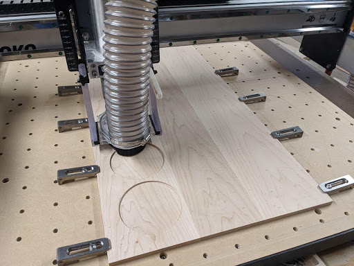
I could then use my CNC to flatten and cut out the profile.
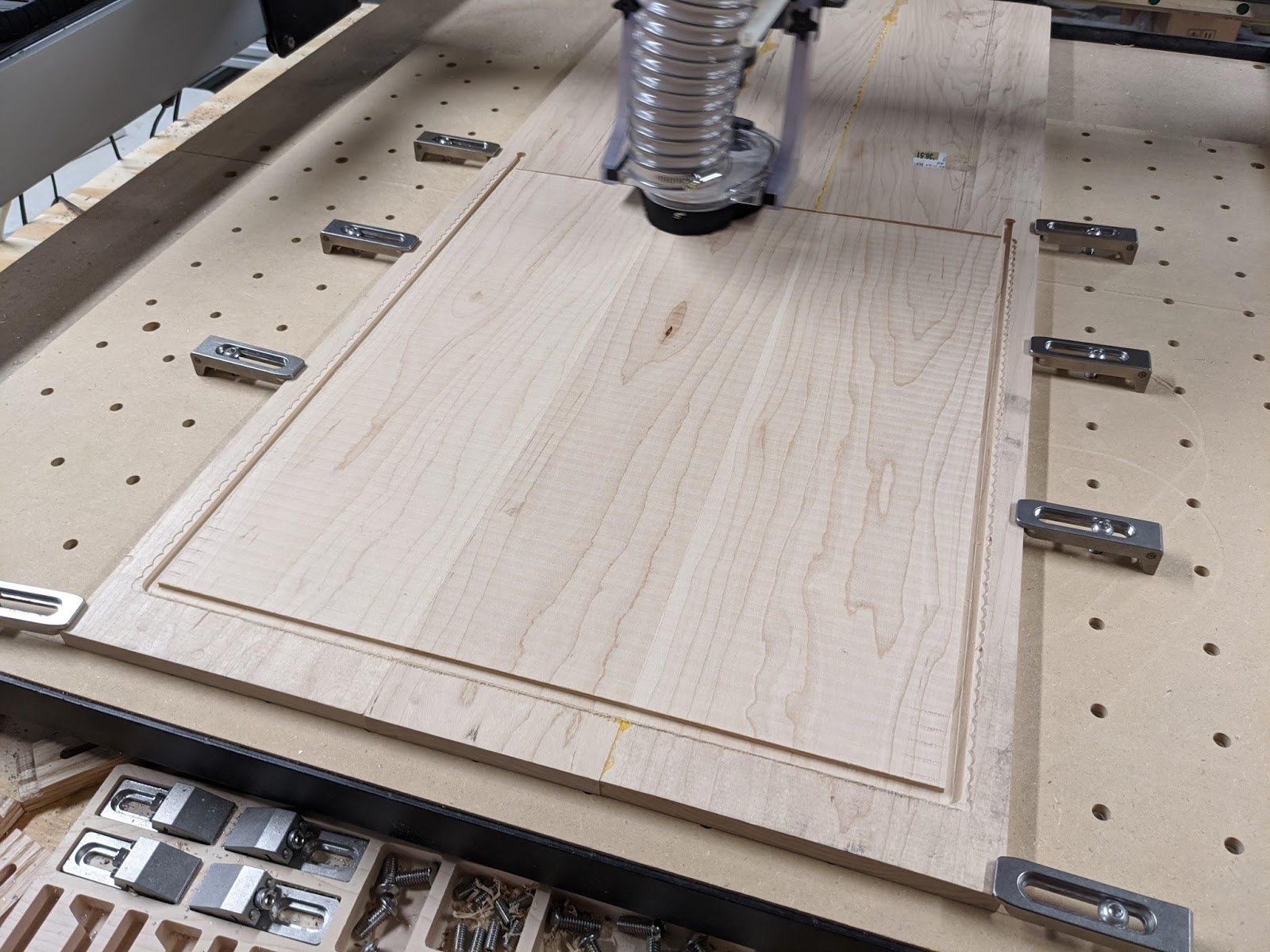
The clock is too big for my Shapeoko XXL so I had to do all the operations in two halves. Once I had the first side done, I could flip it over and flatten out the other side to get the entire face perfectly flat.
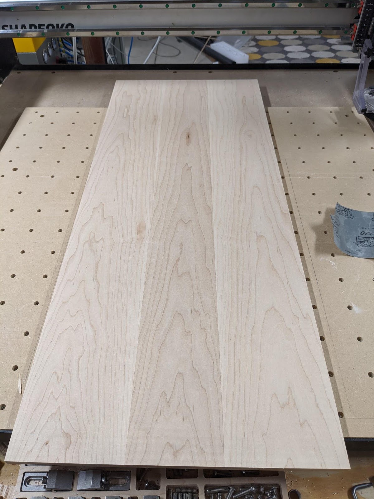
The board was then ready to mill out the pockets for the clocks.
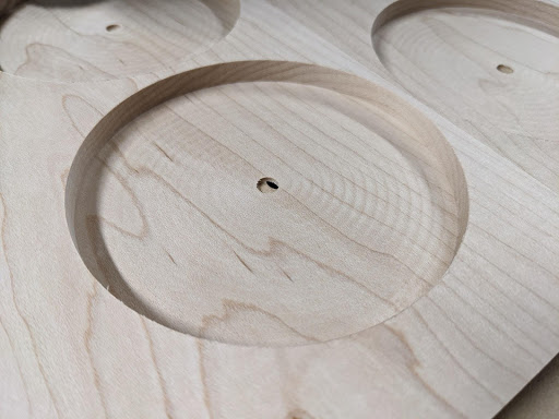
When I made the face plate, it turned out a little thinner than I was originally planning after facing it. That led me to make the bottom of the pockets only 1.5mm thick. This still turned out to be plenty strong.
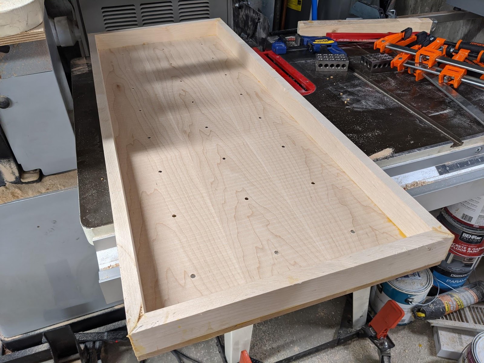
I then built up a frame and glued it together.

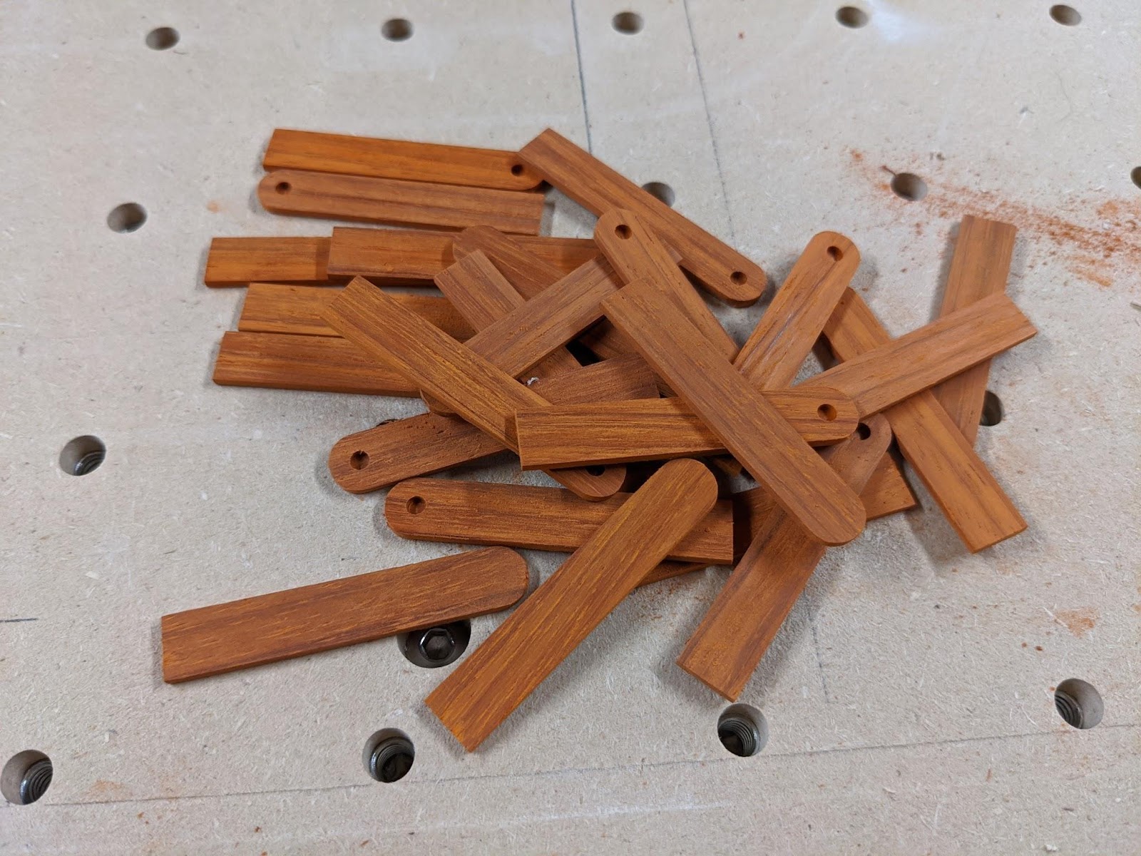
Next, I had to make the hands. I chose to use padauk which is a nice red wood that turns to a deep reddish brown over time. I used this wood for drawer pulls in my kitchen where the clock would be hung and I thought it would look good if they matched.
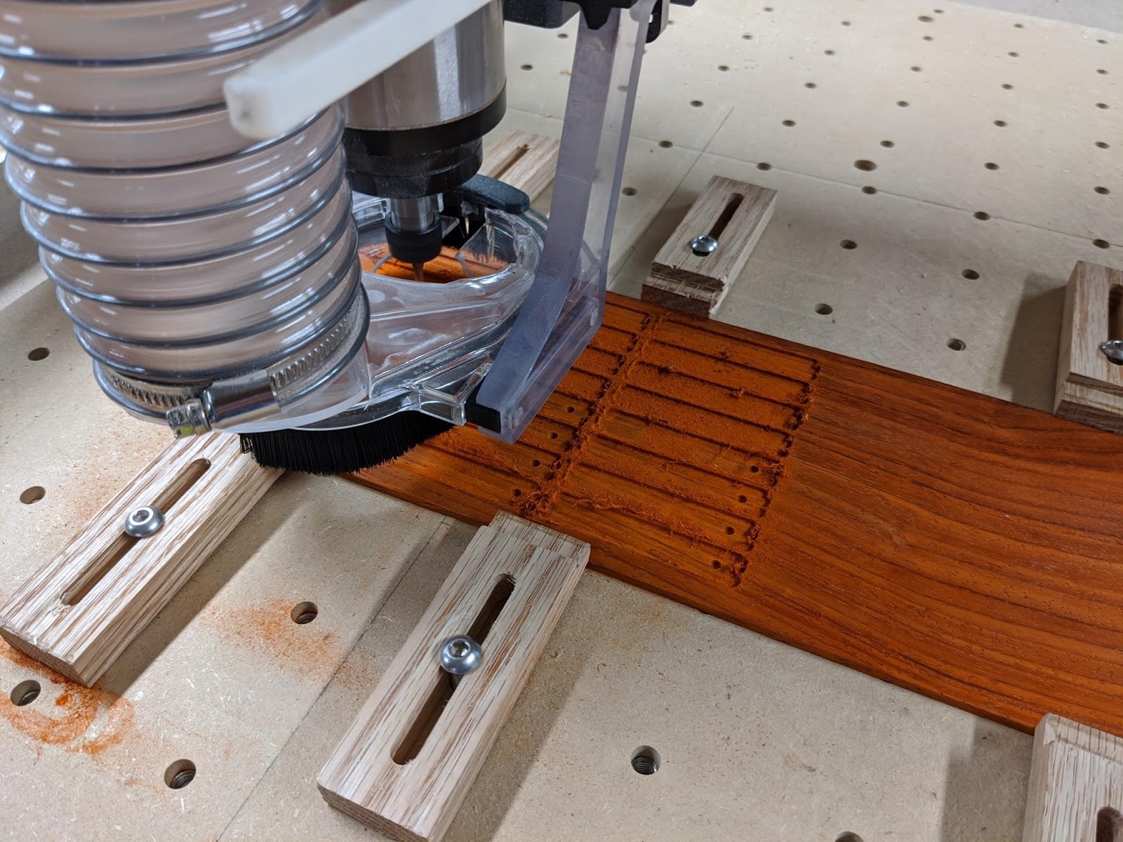
The hands were machined out of ⅛” stock that I milled down to 2mm thick.
With the hands done, I glued all the movement assemblies to the clock.
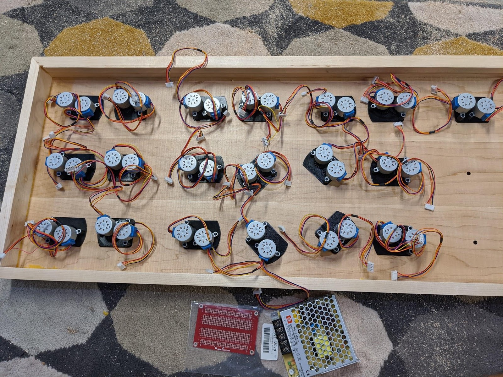
Four of them are rotated at weird angles to make room for the power supply. This is a 12V 6A supply that is plenty for all the motors.
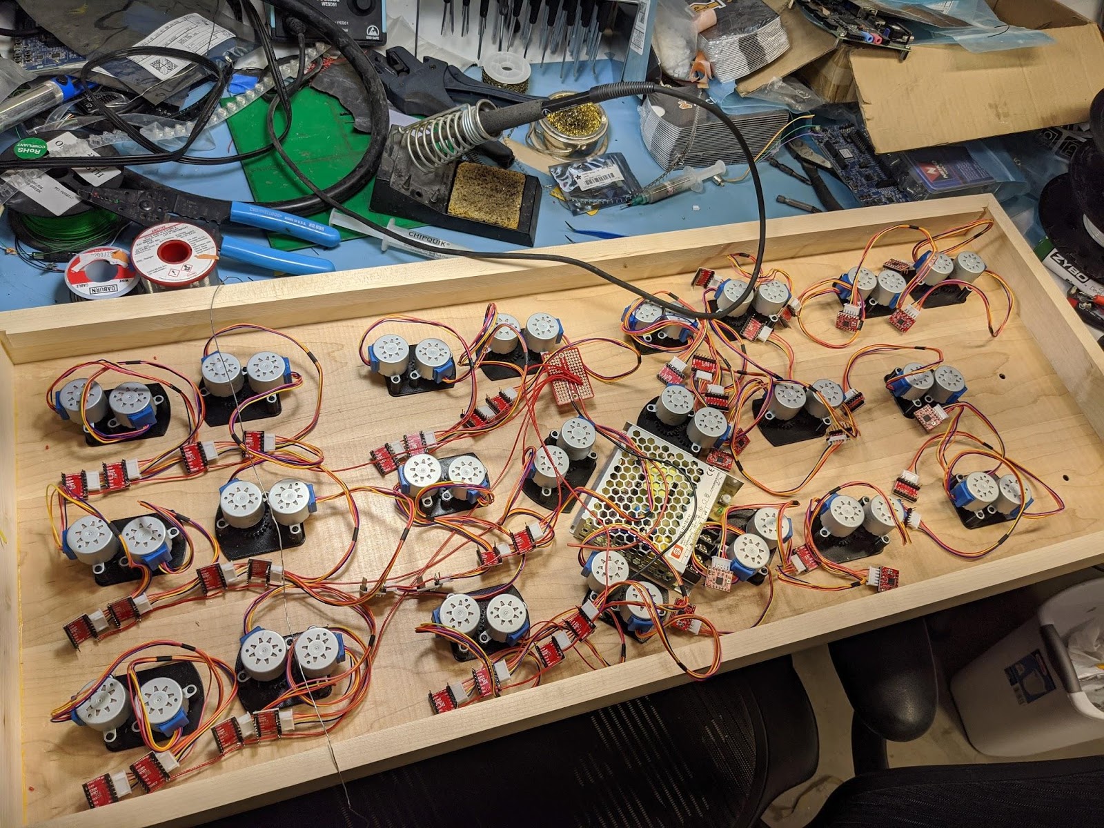
I used generic A4988 stepper drivers to control the motors. I was able to bend the motor pins and plug the motors directly into them after swapping two of the wires on the motor's connector.


With all these attached, I could start wiring them all up to power.
This picture is missing two movements because I was short 4 motors at the time.
Each driver needed to be wired up to the 12V supply for the motors and 3.3V for the control logic.
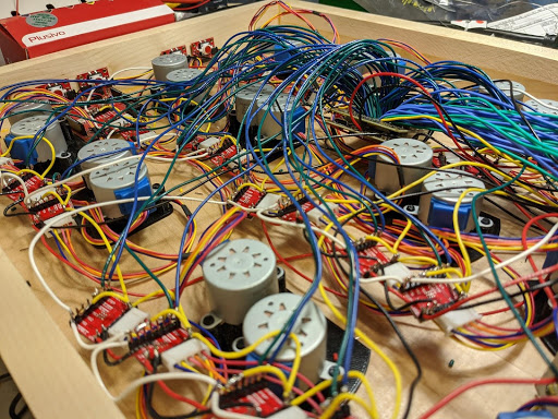
Each group of 6 that makes up a digit also had their enable pins wired together and routed to the Alchitry Au. Every driver had a direction and step signal that had to be wired back to the Au as well. As you can tell from the picture, the wiring quickly became a huge tangle.
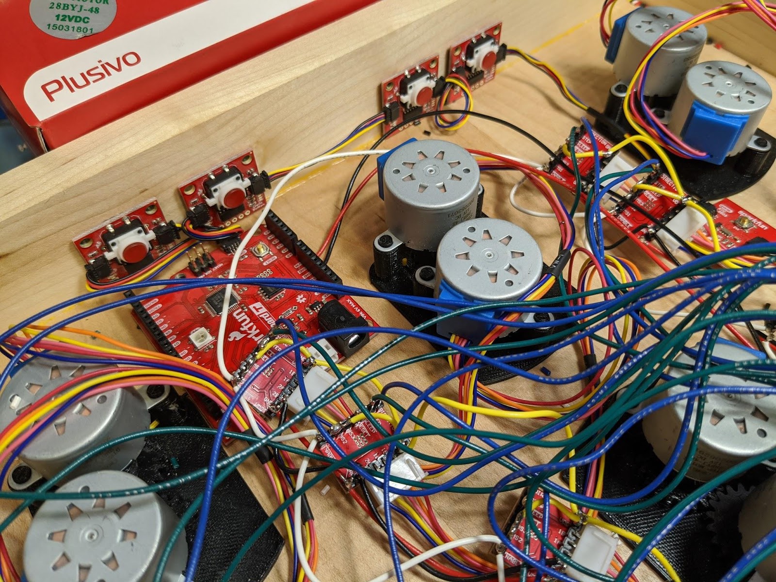
I needed a way to set the time so I added four Qwiic buttons. Since I was already doing enough wiring, using the Qwiic connectors made it a LOT easier. The top pair is hour up/down and the bottom pair is minute up/down.
After the buttons, there is a RV-8803 real-time clock also connected to the Qwiic bus. The RTC being battery backed meant that I wouldn’t need to set the time every time I reprogrammed or unplugged the board.
Finally, the Alchitry Au is connected. It has to be at the end of the chain since it only has one Qwiic connector on it. I also removed the power wire from the Qwiic cable so the 3.3V regulator on the Alchitry Au wouldn’t conflict with the 3.3V regulator on the RedBoard Turbo.
The microcontroller is the RedBoard Turbo. I used this simply because it had a Qwiic connector and I had it on hand. Really, any microcontroller with a Qwiic connector could be used. The computational power needed is minimal.
The Alchitry Au and the RedBoard Turbo both require 5V. I used a small regulator intended for RC vehicles that would regulate the 12V down to 5V at up to 2A.
I wired up the stepper drivers to use half stepping. Initially I set it up to use 1/16 micro stepping but the motors made an audible whine when not on a half or full step. I also really didn’t need the resolution.
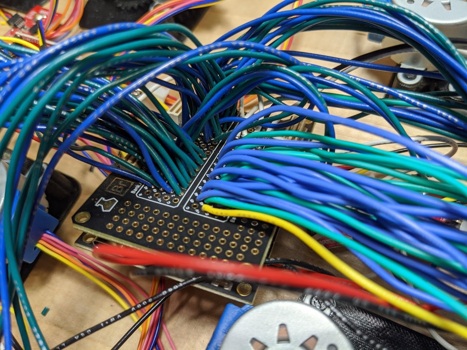
The 102 wires going into the FPGA don’t really matter what pins they connect to. It is only important you keep track of which ones you choose. The actual pinout is defined in the constraint file of the FPGA design.
With all the wiring done, I could clean up the wiring a bit and put the hands on the clock.


That’s basically it for the physical build. The wiring wasn’t complicated, just very tedious.
FPGA
With any FPGA design it is important to outline what you want it to do before you start. In this case I needed to create something that could accept commands over I2C and step the motors accordingly.
I settled on the commands being a number of steps and a value corresponding to the period between steps. I originally thought about making the controller fancier with automatic ramping of the steppers but it turned out not to be necessary and would just complicate coordination between the hands.
I also wanted to be able to queue up a series of commands. That would make the Qwiic timing not important as each command would just be executed one after another.
Finally, I need the design to figure out when steps would be issued and enable/disable the motors accordingly to save power.
The Animator
To start off, I created a module that would control a single stepper motor. This module would accept a command to step so many steps with a specified delay between each step. It would then generate the appropriate direction and step signals for the stepper motor driver.
Here is the code for the module.
module animator (
    input clk,  // clock
    input rst,  // reset
    signed input stepCount[16], // it can be negative to indicate direction
    input delayCycles[16],      // cycles between each step
    input newAnimation,         // flag for new animation
    output busy,                // flag the animator is busy and won't accept animations
    output step,                // step signal for the driver
    output direction            // direction signal for the driver
  ) {

  .clk(clk) {
    // The driver requires each "step" pulse to be at least 1us so we make them 2us
    pulse_extender stepExt(#MIN_PULSE_TIME(2000));

    dff dirCt[8];      // counter for waiting after changing direction. 200ns delay required
    dff counter[16+8]; // counter for delaying between steps. The +8 is the pre-divider

    .rst(rst) {
      fsm state = {IDLE, DIR_WAIT, STEP};
      dff dir;         // saved direction of the motor
      dff delayCt[16]; // saved delay count
      dff steps[16];   // saved number of steps (absolute value)
    }
  }

  always {
    busy = state.q != state.IDLE; // busy when not idle
    step = stepExt.out;           // step output is the extended pulse

    stepExt.in = 0;               // default to no new step
    direction = dir.q;            // output the saved direction

    case (state.q) {
      state.IDLE:
        if (newAnimation && stepCount != 0) {   // if new animation with steps (skip 0 step animations)
          state.d = state.DIR_WAIT;             // move to next state
          dir.d = stepCount[stepCount.WIDTH-1]; // direction is the sign of the step input (0 = positive, 1 = negative)
          steps.d = stepCount[stepCount.WIDTH-1] ? -stepCount : stepCount; // save the absolute value of stepCount
          delayCt.d = delayCycles;              // save the number of delay cycles
        }
      state.DIR_WAIT:
        dirCt.d = dirCt.q + 1;                  // wait for the direction output after it changed
        if (&dirCt.q) {                         // if done waiting
          state.d = state.STEP;                 // move to stepping state
        }
      state.STEP:
        counter.d = counter.q + 1;              // increment step delay counter
        if (counter.q[counter.WIDTH-1-:16] == delayCt.q) { // if counter has reached the delay count
          counter.d = 0;                        // reset counter
          stepExt.in = 1;                       // send a pulse
          steps.d = steps.q - 1;                // decrement the number of steps remaining
          if (steps.q == 1) {                   // if no more are left
            state.d = state.IDLE;               // return to idle
          }
        }
    }
  }
}
The first thing to note is that the stepper controller I used required that the direction input be stable for at least 200ns before and after rising edge of the step input. It also required that the step pulse have a minimum time high or low of 1us.
The step pulse width is easily achieved using the pulse_extender module from the component library. This module takes single cycle pulses and extends them to the specified length. In this case I set the length to be 2us to be nice and safe.
Once a new animation command is received, the direction output is set and the module waits for the dirCt to overflow. This counter holds 256 values and when using a 100MHz clock, that means it waits 2.56us. This is significantly longer than the 200ns required but it ensures that there are no timing issues with the long wires. Tightening the timing here wouldn’t make any performance difference either.
The stepping state increments a counter and steps each time it overflows. This counter has a pre-divider of 8 so each increment of delayCycles in the animation command is 256 extra delay cycles. This pre-divider allowsdelayCycles` to stay relatively small at 16 bits but still allow for a very wide range of speeds.
Even with this pre-divider, I found the lowest delayCycles could be safely set is around 760. That corresponds to 8 seconds for a full rotation.
Enable Gate
The next module to tackle is the enable gate. This module is responsible for gating, or blocking, the new animation flag to the animators while the motors are being enabled. It also makes sure the motors stay enabled long enough after an animation to complete their last step.
The module takes in the new animation pending flags for 12 different motors. It then enables the motors and waits a while, 42ms, for the drivers to re-energize the motors and the motors to settle.
After this period, it allows the pending animation flag to pass onto the animators.
While any animator in the group is running, it keeps the motors enabled. Once the last one is done, it keeps the motors enabled for another 42ms before disabling them.
Here’s the code for the module.
module enable_gate (
    input clk,  // clock
    input rst,  // reset
    output new_animation[12], // output to the animators
    input fifo_empty[12],     // input from fifos (pending animations)
    input animator_busy[12],  // input from animators
    output enable             // output to the stepper drivers
  ) {

  .clk(clk) {
    .rst(rst) {
      dff onCtr[22];          // counter to ensure motors are fully on (22bits ~ 42ms)
      dff offCtr[22];         // counter to keep motors on after animators finish (22bits ~ 42ms)
    }
  }

  sig running; // value used to know when the motors should be on

  always {
    // run when we have pending animations or are actively running
    running = |(animator_busy | ~fifo_empty);

    // enable flag is set when running or onCtr isn't 0 (it is reset after offCtr overflows)
    enable = running || (onCtr.q != 0);

    // pass on new_animation flag only when onCtr is full
    new_animation = ~fifo_empty & 12x{&onCtr.q};

    if (running) {
      offCtr.d = 0;            // reset off counter
      if (!&onCtr.q) {         // if not full
        onCtr.d = onCtr.q + 1; // increment onCtr
      }
    } else {                     // not running
      if (!&offCtr.q) {          // if offCtr not full
        offCtr.d = offCtr.q + 1; // increment offCtr
      } else {                   // if offCtr is full
        onCtr.d = 0;             // reset the onCtr
      }
    }
  }
}
When the module is sitting idle, onCtr is 0 and offCtr will max out. When a pending animation is detected (the fifo isn’t empty), the enable output is set and onCtr is incremented each cycle.
Once onCtr is full, the new_animation flags are passed through.
Once all the animations have been performed, offCtr is incremented. Once it reaches its maximum value, onCtr is reset which disables the motors.
An interesting line to look at is the first line in the always block.
running = |(animator_busy | ~fifo_empty);
This line can be a bit cryptic if you aren’t familiar with bitwise reduction operators. The goal of this line is to take the 12 animator_busy signals and the 12 fifo_empty signals and turn them into a single bit.
First, we can think about a single case. Any one motor is running if the fifo isn’t empty or it is currently busy. This can be taken care of by animator_busy | ~fifo_empty. A single pipe (vertical bar, |) is a bitwise OR. This will OR each of the bits of the two operands together keeping the bit width the same. The tilda (~) is a bitwise inversion. This flips each of the bits in fifo_empty.
After those operations we now have a 12 bit wide signal that says when each animator is running. However, we need to condense this into a single bit. The OR reduction operator is used here. The pipe operator, when placed in front of a value without a preceding value, will OR all the bits in the signal together and output a single bit.
In this case, that means if any of the motors are running, running will be 1.
Later on in the module, I use the AND reduction operator to check if all the bits in a signal are 1 (aka the max value). This works the same way as the OR reduction operator but ANDs ever bit together. Basically, it is 1 if they all are 1 and 0 otherwise.
You can also use the carrot (^) to perform an XOR reduction which will be 1 if there are an odd number of 1s.
Qwiic
We are now going to look at the top level module which takes care of the Qwiic interface and glues everything together.
Let’s just jump into it.
module au_top (
    input clk,              // 100MHz clock
    input rst_n,            // reset button (active low)
    output led [8],         // 8 user controllable LEDs
    input usb_rx,           // USB->Serial input
    output usb_tx,          // USB->Serial output
    output step[48],        // step output to motors
    output dir[48],         // direction output to motors
    output enable[4],       // enable output to motors (one per digit)
    inout sda,              // Qwiic SDA
    input scl               // Qwiic SCL
  ) {

  sig rst;                  // reset signal

  .clk(clk) {
    // The reset conditioner is used to synchronize the reset signal to the FPGA
    // clock. This ensures the entire FPGA comes out of reset at the same time.
    reset_conditioner reset_cond;

    dff ani_id[6];            // saved ID for the motor
    signed dff ani_steps[16]; // saved number of steps
    dff ani_delay[16];     // saved delay counts
    dff byteCt;               // byte flag for 16bit numbers

    .rst(rst) {
      i2c_peripheral qwiic (.sda(sda), .scl(scl)); // i2c peripheral module for qwiic interface

      dff ledReg[8]; // reg to hold the LED values (useful for qwiic testing)

      fsm state = {IDLE, ENABLE, LED, ANIMATION_STEPS, ANIMATION_DELAY, ANIMATION_PUT};

      animator animators[48]; // need 48 individual animators (one per motor)

      // need one fifo per animator, 32 bits wide for 16 bit steps and 16 bit delay
      // the 128 depth is definitely overkill and 16 would probably be plenty for the
      // current usage.
      fifo ani_fifos[48] (#SIZE(32), #DEPTH(128));

      enable_gate gates[4]; // modules to control the enable signals (one per digit)
    }
  }

  var i;

  always {
    reset_cond.in = ~rst_n; // input raw inverted reset signal
    rst = reset_cond.out;   // conditioned reset

    led = ledReg.q;         // output ledReg to the leds

    usb_tx = usb_rx;        // echo the serial data

    // the ~ here flips every motor direction so positive steps would go clock-wise
    // the 48hAAAAAAAAAAAA constant has every other bit flipped so the geared motors
    // and direct drive motors will turn the hands the same way
    dir = animators.direction ^ ~48hAAAAAAAAAAAA;
    step = animators.step;
    enable = ~gates.enable; // enable of the controllers is active low so invert the bits

    qwiic.tx_data = 8bx; // this design is "write only" and never sends data to the microcontroller
    qwiic.tx_enable = 0; // never send data

    // combined groups of 12 motors for the four enable gates
    for (i = 0; i < 4; i++) {
      gates.fifo_empty[i] = ani_fifos.empty[i*12+:12];
      gates.animator_busy[i] = animators.busy[i*12+:12];
      animators.newAnimation[i*12+:12] = gates.new_animation[i];
      // only remove a value from the fifo when the gate passes the new_animation flag
      // and the animator isn't busy
      ani_fifos.rget[i*12+:12] = gates.new_animation[i] & ~animators.busy[i*12+:12];
    }

    // for each motor split the fifo output to the animator signals
    for (i = 0; i < 48; i++) {
      animators.stepCount[i] = ani_fifos.dout[i][15:0];
      animators.delayCycles[i] = ani_fifos.dout[i][31:16];
    }

    // default to no new animations
    ani_fifos.wput = 48b0;

    // always input the saved delay and steps
    // this line takes the two values, joins them, packs them into a 1x32 array,
    // and finally duplicates it 48 times into a 48x32 array
    // essentially, it just feeds the same 32 bits to each of the 48 fifos
    ani_fifos.din = 48x{{c{ani_delay.q, ani_steps.q}}};

    case (state.q) {
      state.IDLE:
        byteCt.d = 0;
        if (qwiic.rx_valid) {                    // new data
          case (qwiic.rx_data) {                 // case on the value
            8hFF: state.d = state.LED;           // make "address" FF the LEDs for testing
            default:
              ani_id.d = qwiic.rx_data[5:0];     // default to "address" as the motor id
              state.d = state.ANIMATION_STEPS;
          }
        }
      state.LED:
        if (qwiic.rx_valid) {        // if new data
          state.d = state.IDLE;      // return to idle
          ledReg.d = qwiic.rx_data;  // show value on the LEDs
        }
      state.ANIMATION_STEPS:
        if (qwiic.rx_valid) {                                // if new data
          ani_steps.d = c{ani_steps.q[7:0], qwiic.rx_data};  // save byte and shift old byte
          byteCt.d = ~byteCt.q;                              // flip byte counter
          if (byteCt.q == 1) {                               // if second byte
            state.d = state.ANIMATION_DELAY;                 // go to delay capture state
          }
        }
      state.ANIMATION_DELAY:
        if (qwiic.rx_valid) {                                // if new data
          ani_delay.d = c{ani_delay.q[7:0], qwiic.rx_data};  // save byte and shift old byte
          byteCt.d = ~byteCt.q;                              // flip byte counter
          if (byteCt.q == 1) {                               // if second byte
            state.d = state.ANIMATION_PUT;                   // go to put state
          }
        }
      state.ANIMATION_PUT:
        state.d = state.IDLE;                                // return to idle
        ani_fifos.wput[ani_id.q] = 1;                        // put the new animation into the correct fifo
    }

    if (qwiic.stop) {          // if I2C stop condition is detected
      state.d = state.IDLE;    // reset to IDLE
    }
  }
}
The Qwiic interface is handled by the i2c_peripheral module. This module is a bit complicated since it breaks out the start/stop signals and requires you to provide direction when it should accept data or send data.
For our case, we can simplify it a lot by only reading in data. The important flags become rx_valid which tells us a new byte has been read in and stop that says the I2C transaction was stopped and we should reset. The output rx_data has the value of the byte read in when rx_valid is high.
If you want to respond to something, you need to monitor the start, next, and write flags. On the next clock cycle you can set tx_enable to 1 and provide data to send on tx_data. This will cause the module to write that byte instead of listen for one.
The start flag signals your ID was detected on the bus. At the same time that this is set, write will tell you if the last bit in the ID byte indicated a read (0) or write (1).
Again, we can ignore all this for this design.
The protocol I used for each transaction is the first byte is the address followed by the command’s data. For addresses 0-47, four bytes are expected. The first two are the step count and the second two are the delay count. Address 8hFF is special in that it only expects one byte after it and is used to set the LEDs on the Au. This is useful for testing the Qwiic bus.
I also made it so that you don’t need to start/stop the I2C transaction for each animation. Every 5 byte packet is a valid animation and it will loop after the last byte is received. This allows you to send all 48 motors a new animation in a single transaction.
FIFOs
This design is set up with 48 FIFOs to hold additional animations while the animators are busy. These are created from the fifo component in the component library.
Each FIFO is 32 bits wide and 128 entries deep. The 32 bits are split into 16 for the delay and 16 for the step counts. 128 entries deep is overkill for the current usage but would allow for many short animations to be stacked if I wanted to implement ramping and faster movements on the other side. The Au has plenty of built-in block RAM to fit all this anyways.
The FIFO follows a first-word-fallthrough style where when empty is 0, indicating there is data, the value is already available on dout. Setting rget to 1 will remove the entry and show the next entry on the following clock cycle.
To supply data to the FIFO, simply put the data on din and set wput to 1. You may also want to check that full isn’t 1, or your data may be ignored.
Bit Assignments
In the beginning of the always block there is quite a bit of array/bit manipulation.
In Lucid, you can conveniently make modules arrays and have their ports packed into arrays. In some cases of our design, like the step outputs, we can directly assign these arrays as the bits perfectly line up.
In other cases, we need to split them out into subsections. When this happens it is convenient to use for loops. Remember that for loops can’t be realized in hardware and need to have a fixed number of iterations so they can be unrolled during synthesis. They are simply a way to write things more compact.
For example, the first for loop goes through four iterations with i being 0 through 3.
The first line will evaluate to the following for the first iteration.
gates.fifo_empty[0] = ani_fifos.empty[0+:12];
The [0+:12] bit selector means starting at bit 0, select 12 bits above it. So bits 0-11 are selected.
In the next iteration, it will evaluate to the following.
gates.fifo_empty[1] = ani_fifos.empty[12+:12];
Here, the second enable gate gets the bits 12-23.
All four iterations could be listed out.
gates.fifo_empty[0] = ani_fifos.empty[0+:12];
gates.fifo_empty[1] = ani_fifos.empty[12+:12];
gates.fifo_empty[2] = ani_fifos.empty[24+:12];
gates.fifo_empty[3] = ani_fifos.empty[36+:12];
This would create an identical circuit in the FPGA. However, I’m sure you’ll agree that this is cumbersome to type out and maintain.
It is very common to use the start/width bit selectors in for loops instead of the start/stop bit selectors. This is because you can’t use start/stop selectors with non-constant values.
The start/width selector used above ensures that the width of the selection is always 12 bits wide. You can’t realize a signal that changes width in hardware as you can’t spontaneously create or remove connections.
In this case I used the up variant of the selector by using the +:. You can also use -: to use the down variant of the selector. This selects the start bit and the bits below it.
For example, [11-:12] is the same as [0+:12]. They both select bits 0-11.
Pin Assignments
At this point you may be wondering how the step and dir signals map to the IO pins on the Au.
This mapping is defined in a constraint file. In this case they are in the clockclock.acf file. The acf extension is for Alchitry Constraint File. This format is very simple and allows you to specify the pin names as the pins on the Alchitry boards instead of the FPGA. For example, A2 maps to the second pin of the top left header (bank A) on the Au.
If you open this file you’ll see a whole bunch of lines that look like this.
pin step[0] A2;
pin dir[0] A3;
Each IO port needs to be mapped to a physical pin. The format is the pin keyword followed by the signal name and finally the physical pin location.
You can also add the pullup or pulldown keyword to add an internal pullup/down resistor to the pin. However, `pulldown is ignored on the Cu as the Lattice FPGA doesn’t have internal pulldown resistors.
Most of the pins on an FPGA are fully interchangeable and the pinout I used for the clock was super arbitrary with the exception of the Qwiic signals since they are wired to the Qwiic connector.
All that was important for this project was that I kept them all straight.
Software Setup and Programming
Note: This example assumes you are using the latest version of the Arduino IDE on your desktop. If this is your first time using Arduino, please review our tutorial on installing the Arduino IDE. If you have not previously installed an Arduino library, please check out our installation guide.
The microcontroller I used was the RedBoard Turbo, but as I said before, any board with a Qwiic connector could likely be used.
First, I had to install the libraries for the board and the Qwiic RV8803 RTC and buttons. The buttons below will take you to the respective setup tutorials for each.
The code itself isn’t too complicated but the structure is something I end up doing for many designs.
Basically, I built up layers of abstraction until I got to an easy to use layer that made managing the numbers and performing animations easy.
The first layer is, of course, the FPGA. The FPGA gives us an interface to make a motor perform a certain number of steps with a fixed delay between them.
I used the Wire library built into Arduino to manage the I2C bus. This allowed me to make a simple function that would send a single animation.
language:c
void sendAnimation(uint8_t id, int16_t steps, uint16_t delay_cycles) {
  int32_t p = currentPosition[id] + steps;
  while (p < 0) p += FULL_CIRCLE;
  currentPosition[id] = p % FULL_CIRCLE;
  Wire.write(id);
  Wire.write((uint8_t)(steps >> 8));
  Wire.write((uint8_t)(steps & 0xFF));
  Wire.write((uint8_t)(delay_cycles >> 8));
  Wire.write((uint8_t)(delay_cycles & 0xFF));
}
Two special things here is that I have a constant FULL_CIRCLE declared which is the number of steps in a full rotation. This is 4096 in my case.
This is used to update a global array of position values of the motors. By always using this function to send the animations, the position of the motors is known.
It isn’t very convenient to think of motion in terms of steps and delays. Instead, it is much easier to think of them in terms of degrees and duration. In other words, instead of thinking “take 2048 steps with 760 delay cycles between each step” it makes much more sense to think “turn 180 degrees over 4 seconds.”
I wrote a function that could take care of that translation.
language:c
void animate(uint8_t id, float deg, float duration) {
  float steps = deg * FULL_CIRCLE / 360.0f;
  if (steps > 32767 || steps < -32768) {
    animate(id, deg / 2, duration / 2);
    animate(id, deg / 2, duration / 2);
    return;
  }

  float cycles = constrain(duration * 390625 / abs(steps), 760, 65535);

  sendAnimation(id, (int16_t)steps, (uint16_t)cycles);
}
First, it turns the degrees into steps by again using the FULL_CIRCLE constant. It then checks if there are too many steps for a single animation command and recursively calls itself with half the animation each.
The delay cycles are then calculated. The 390625 value is the number of cycles in a second (100,000,000 / 256 = 390,625). The cycles need to be bound to the range of 760 to 65535. The 760 minimum was empirically found by testing how fast the motors could reliably spin without skipping a step. It is also 8 seconds per revolution.
The upper bound is really high and shouldn’t ever be hit. It would take 687 seconds to do a full rotation. The current design can’t go slower than this. If you needed it to, you would have to change the FPGA’s pre-scaler or the size of the delay cycle value.
The final abstraction I needed was a function to simply tell the motor to move to a position. This would use the currentPosition value to calculate the minimum rotation needed to get to that point. This is helpful when showing the actual time since I can just call it with all the positions the hands need to be in and don’t have to adjust for where they currently are.
language:c
void moveTo(uint8_t id, float pos, float duration) {
  float curDeg = (float)currentPosition[id] * 360.0f / FULL_CIRCLE;
  float angle = pos - curDeg ;

  if (angle > 180)
    angle = angle - 360;
  if (angle < -180)
    angle = 360 + angle;

  animate(id, angle, duration);
}
It starts by calculating the angle the hand is currently at. Then it gets the angle it needs to move by subtracting the desired angle by the current angle.
This angle may end up being the long way around; the two if statements check for this and switch it to the smaller of the two paths. For example, if the difference of the angles was 270, it would be better to move -90 degrees instead.
To show the actual time, I needed a map for all the digits. This was easy enough to do by simply drawing out how I wanted each number to look and writing down the angles for each hand.
I entered all these into a 2D array that could be used to look up any digit.
language:c
const float digitAngles[10][12] = {{270, 180, 0, 180, 270, 0, 90, 180, 0, 180, 90, 0}, // 0
  {180, 180, 0, 180, 0, 0, 225, 225, 225, 225, 225, 225}, // 1
  {270, 180, 270, 0, 270, 270, 90, 90, 90, 180, 90, 0}, // 2
  {270, 180, 0, 180, 270, 0, 90, 90, 90, 90, 90, 90}, // 3
  {180, 180, 0, 180, 0, 0, 180, 180, 90, 0, 225, 225}, // 4
  {270, 270, 270, 180, 270, 0, 90, 180, 90, 0, 90, 90}, // 5
  {270, 270, 270, 180, 270, 0, 90, 180, 0, 180, 90, 0}, // 6
  {270, 180, 0, 180, 0, 0, 90, 90, 225, 225, 225, 225}, // 7
  {270, 180, 270, 0, 0, 270, 90, 180, 90, 0, 0, 90}, // 8
  {270, 180, 0, 180, 0, 0, 90, 180, 90, 0, 225, 225} // 9
};
With this, I could use the RTC to get the time and display the digits.
language:c
void showTime() {
  uint8_t digits[4];
  digits[0] = rtc.getMinutes() % 10;
  digits[1] = rtc.getMinutes() / 10;
  digits[2] = rtc.getHours() % 10;
  digits[3] = rtc.getHours() / 10;
  for (uint8_t d = 0; d < 4; d++) {
    Wire.beginTransmission(0x50);
    for (uint8_t m = 0; m < 12; m++) {
      moveTo(m + 12 * d, digitAngles[digits[d]][m], 4.0f);
    }
    Wire.endTransmission();
  }
}
It is worth mentioning that my code assumes the hands start at the 12:00 position (straight up). This is the 0 degree mark for all my positions.
In the Arduino loop() function, I put code that would check the RTC every 100ms and update the time if it changed.
If the hour changed, I also had it perform an animation. I wrote three simple ones that it randomly selects to perform before settling on the new hour.
Inside loop() I also check the state of the four buttons. My original plan was to use the Qwiic Button’s FIFO interface to keep track of each press, but I ran into a bug that I outlined here.
Instead, I ended up keeping track of the state myself and just used the isPressed() function to check their current state.
When any individual button is pressed, I update the time. The four buttons allow me to set the minutes and hours independently.
I also added a feature where if you press both hour up and hour down at the same time, the hands will all move to the 12:00 position. This is incredibly helpful if you need to power off the clock or reprogram the Arduino as you don’t have to manually readjust every hand.
That about sums up the design. Take a simple interface and build upon it until it is useful.
Troubleshooting
If your product is not working as you expected or you need technical assistance or information, head on over to the Alchitry Forums. This is a great place to do some initial troubleshooting as well as to find and ask for help.

Conclusion
This project turned out to be substantially more work that I originally thought it would when I started. The vast majority of my time was spent with the physical build and the wiring. It also took me a while to come up with a solid working movement design. The FPGA and Arduino designs actually came together with minimal hiccups.
Using the Qwiic connector on the Au to talk to a microcontroller is likely to be one of its most useful use cases. I was pleasantly surprised by how easy it was to set up on the Arduino side having never used Qwiic (or I2C) on an Arduino before.
There are a few things that could be improved if someone were to make another one of these.
First, the clock is pretty loud. The individual motors are all pretty quiet, but then you glue them to a pretty thin piece of wood it really amplifies it. I should have looked into some kind of sound dampening way to mount the motors. Maybe using some kind of soft rubber glue instead of super glue to attach them. The wood is also only 1.5mm thick for most of the face which really makes it reverberate.
I’m thinking I may try to pour liquid rubber onto the backside of the board to help dampen the noise.
The other major issue is that the stepper motors are internally geared and the gearing has backlash. This means that depending on the direction the hand was moving it may or may not be where it is supposed to be. They seem to get off a few degrees when switching directions due to the play. It isn’t the end of the world but it is off just enough to be painfully obvious. I may be able to write some code that could compensate for it but it isn’t consistent across motors and would have to be fine tuned.
This could be fixed with motors that aren’t geared. I had a hard time finding small stepper motors for this though that weren’t prohibitively expensive.
I hope this demo project has given you a good example of what can be done with an FPGA and hopefully sparks some ideas for your own projects!
Resources and Going Further
Production files:
Alchitry's website has more great resources, including tutorials, projects, and the Alchitry Forum.
- Alchitry
- Alchitry Au+ Schematic (PDF)
- Alchitry Au Schematic (PDF)
- Alchitry Cu Schematic (PDF)
- Xilinx Artix 7 User Guide
If you'd like to delve deeper into the world of FPGAs and Lucid, check out "Learning FPGAs: Digital Design for Beginners with Mojo and Lucid HDL" by Justin Rajewski. It's available on Amazon and is a great resource for understanding and ultimately designing your own FPGAs.
We are continually expanding our offering of tutorials and products related to FPGAs. Check out some of the following tutorials!
How Does an FPGA Work?
First FPGA Project - Getting Fancy with PWM
External IO and Metastability