TeensyView Hookup Guide
 MTaylor
 Hardware Overview and Assembly
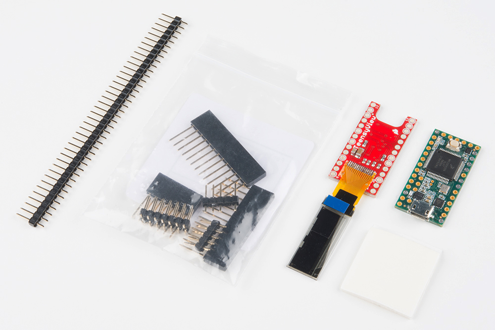
The hardware comes as a headerless PCB with OLED soldered on. There are jumpers on one side to configure how the OLED communicates with the attached Teensy. You'll need to set the jumpers, solder the TeensyView to the Teensy or to headers, then affix the OLED.
This section instructs the use of male headers on the TeensyView, with stackable headers on the Teensy.
The TeensyView has two available connections for the OLED communication lines, to allow compatibility with various boards. One side (factory configuration/'Standard') is all connected by copper jumpers, with the 'Alternate' side available to reconfigure the connections.
Use this table to determine which pins to use for the TeensyView, or leave them set by copper to the standard pins if no other resources are in use.
Jumper Default Copper Jumpers
(Standard)Audio Board Compatible
(Alternate)Prop Shield Compatible RST 15 2 15 (Std.) D/C 5 21 21 (Alt.) CS 10 20 20 (Alt.) SCLK 13 14 13 (Std.) DATA 11 7 11 (Std.) If necessary, carefully cut the copper jumper on the board and apply solder to reroute the signal.
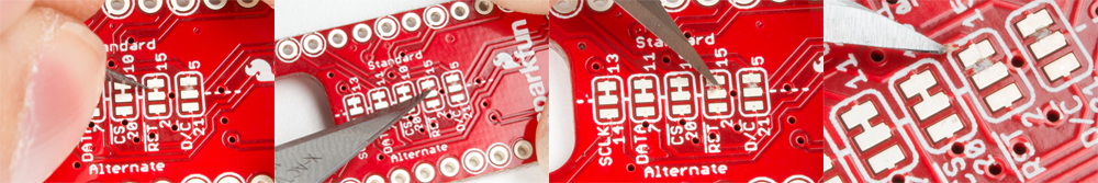
 Cutting the copper traces: Make two cuts, one on each end of the copper link, then remove the excess copper with a slight twist of the knife. Solder connections are not shown here, but if you remove the copper link you will need to apply a solder jump between two of the pads of the jumper!
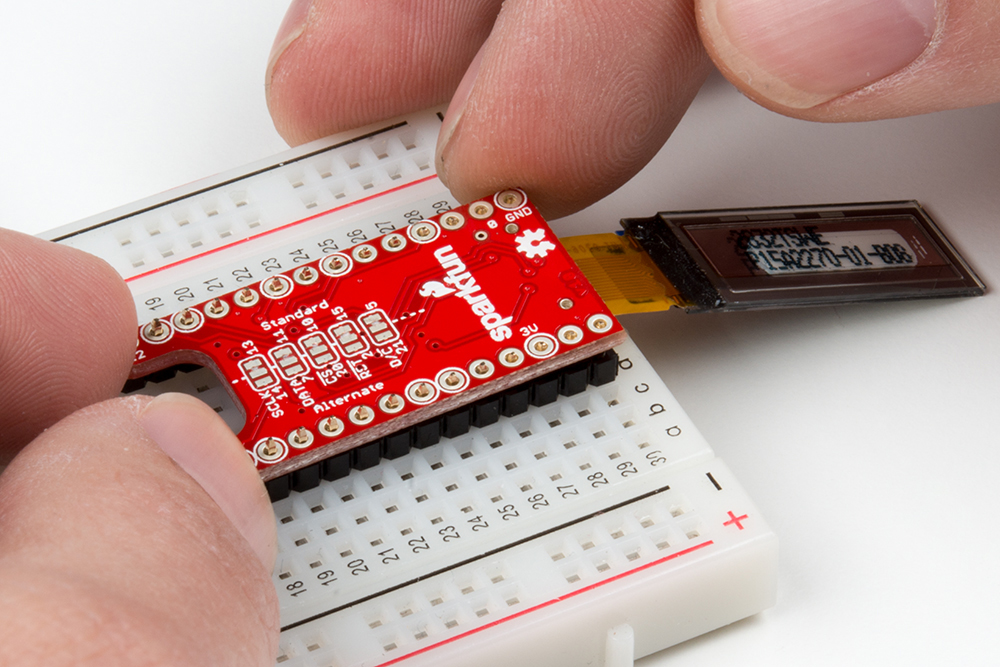
Separate two 14-pin lengths of straight male header and fit them into the breadboard, then set the PCB onto them with the jumpers facing up and the LCD facing down. The LCD will fold over and cover the jumpers.
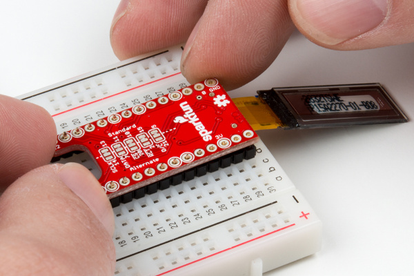 Notice that the OLED is soldered to the back side and folds around the edge of the PCB, covering the selection jumpers. This is so the jumpers can still be accessed if the TeensyView is more permanently attached to a Teensy.
Next, solder the headers onto the TeensyView using a flux core solder. The silkscreen rings denote pins that are electrically connected to the TeensyView circuitry. You can choose to either solder all pins, for better mechanical stability, or just the connected pins, if you foresee removal of the pins in the future. This board is assumed to be the top of a stack and may not need all of the Teensy's signals passing through.
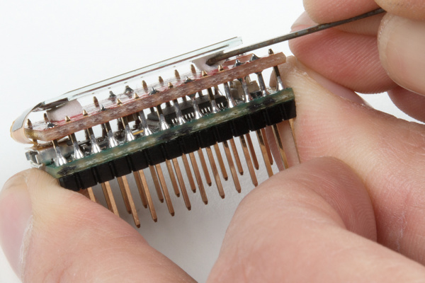
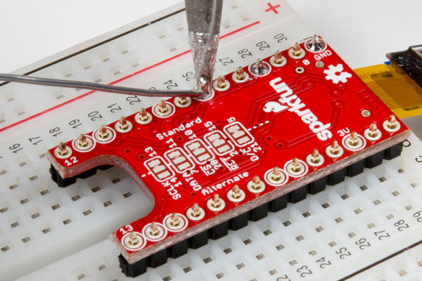 Attaching the straight headers to the Teensy using a breadboard.Note: There are 12x silkscreen rings highlighted. You will only be using 5x of the standard pins and 2x for power on the Teensy as shown earlier in the table of the jumpers. 5x of the remaining pins are the alternate pin connections.
Now that the TeensyView has headers, it can be used to help keep the Teensy Stackable Headers in place for assembly. Put the 6 long and two 13 long headers onto the TeensyView, then place the Teensy on and apply solder.
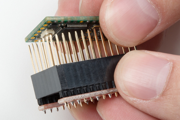 Using the TeensyView as a soldering jig
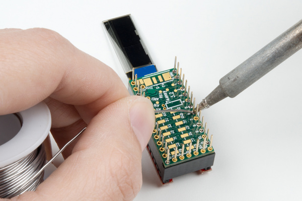 Attaching the Teensy Header Kit
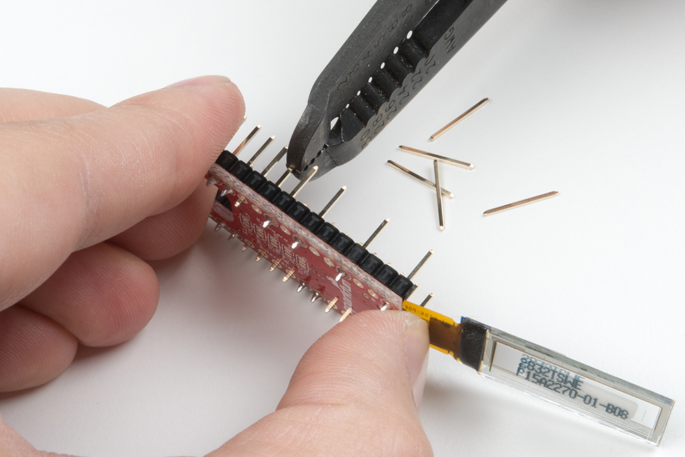
If you've decided to only solder the electrically connected pins, now's a good time to pull the spare pins. Hold the TeensyView firmly with one hand and give a steady pull with pliers or wire strippers. To double check, there should only be pins left in the holes with silkscreen rings.
 Pulling the pins
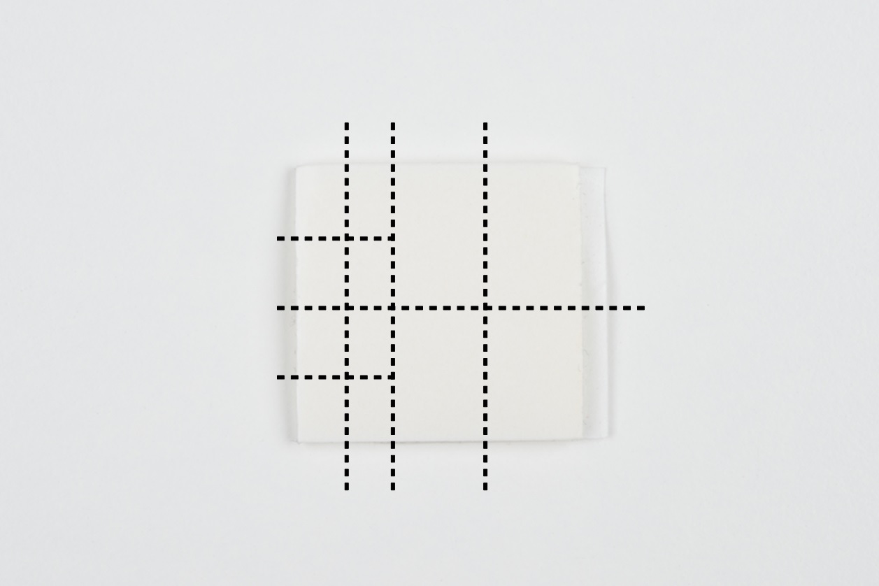
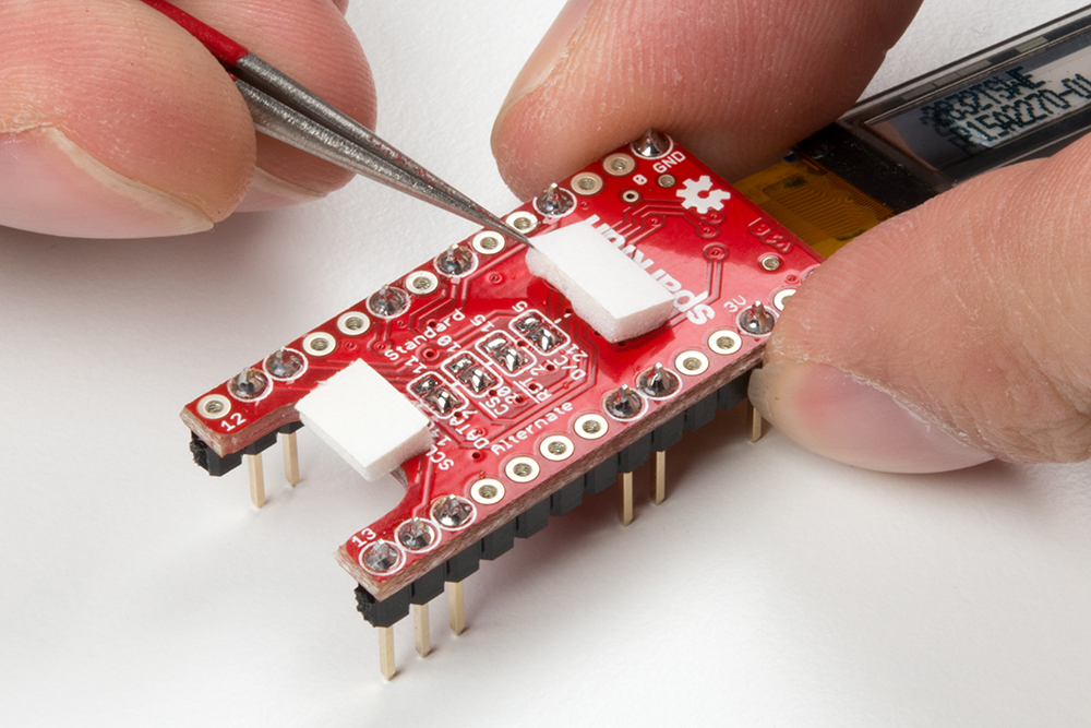
Apply the screen using the double-sided foam. It's best to start with little pieces until you're sure of the configuration you would like. Visualize how the foam will be divided or draw on it with a pen. Then use your scissors to cut off strips, and subdivide from there.
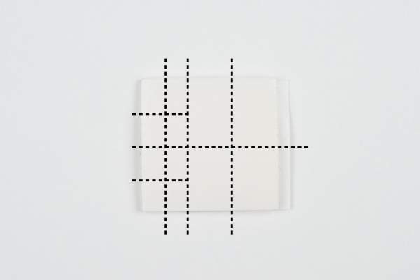 A way to divide the square of foam tape
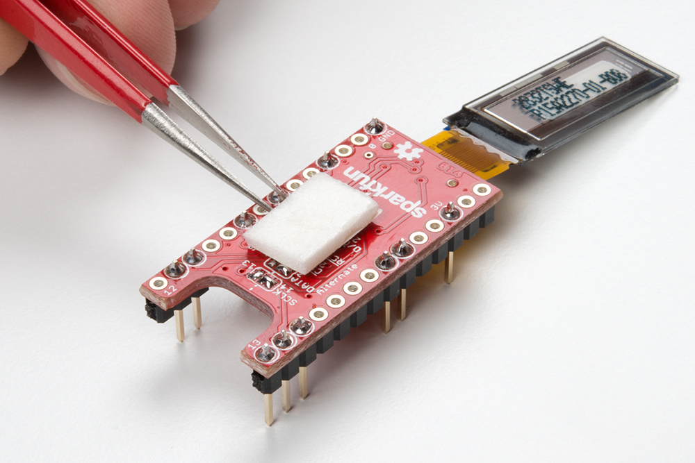
A couple small pieces go a long way to keep it in place, while a large piece can keep it there on a more permanent basis. Reasons to remove the screen may be to adjust left-right justification (to match a chassis cutout, for example) or to change the configuration of the pins. It can be tempting to just start with a large piece, but don't! The foam is extremely grippy once it's set.


Two small pieces keep the screen from flopping around. A large piece can be used as a permanent solution. 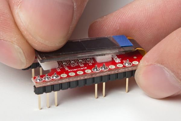 Carefully set down the glass.
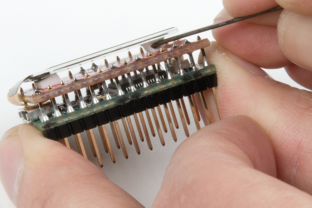
Oh no! You've put your screen down too early and need to adjust something! Don't worry, but don't just pry up the glass either. Use a thin, blunt tool to push the meat of the foam out from the side.
 Breaking the foam structure without applying force to the OLED glass.
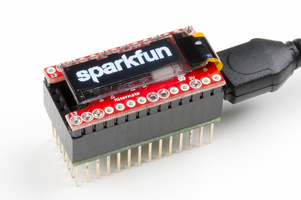
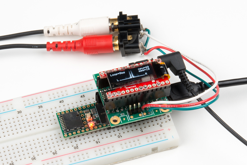
Attach the TeensyView and USB cable. Then run the examples. The TeensyView has a few pins (labeled
0,13,14,3VandGND) to help make sure it's oriented the right way. Here's what the final stack should look like on the Teensy 3.2 and Teensy 3.6. As you can see, the bend of the OLED's flex cable is on the side of the Teensy's USB connector.


 |
 |
| TeensyView on Teensy 3.2 | TeensyView on Teensy 3.6 |