SparkFun RTK Surveyor Hookup Guide
 Nate, Ell C
Hardware Overview
The RTK Surveyor is a fully enclosed, preprogrammed device. There are very few things to worry about or configure but we will cover the basics.
Switches
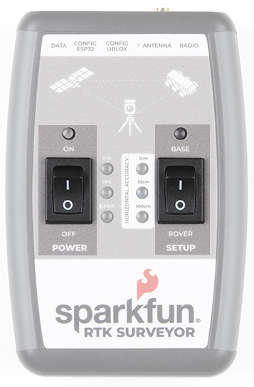
Setup
This device can be used in three modes:
- GNSS Positioning (~30cm accuracy)
- GNSS Positioning with RTK (1.4cm accuracy)
- GNSS Base Station
When the SETUP switch is set to Rover the device will enter Position mode. RTK Surveyor will receive L1 and L2 GNSS signals from the four constellations (GPS, GLONASS, Galileo, and BeiDou) and calculate the position based on these signals. Similar to a standard grade GPS receiver, the RTK Surveyor will output industry standard NMEA sentences at 4Hz and broadcast them over any paired Bluetooth device at 115200bps. The end user will need to parse the NMEA sentences using commonly available mobile apps, GIS products, or embedded devices (there are many open source libraries). Unlike standard grade GPS receivers that have 2500m accuracy, the accuracy in this mode is approximately 300mm horizontal positional accuracy with a good grade L1/L2 antenna.
When the SETUP switch is set to Rover and RTCM correction data is sent into the radio port or over Bluetooth, the device will automatically enter Positioning with RTK mode. In this mode RTK Surveyor will receive L1/L2 signals from the antenna and correction data from a base station. The receiver will quickly (within a few seconds) obtain RTK float, then fix. The NMEA sentences will have increased accuracy of 14mm horizontal and 10mm vertical accuracy. The RTCM correction data can be obtained from a cellular link to online correction sources or over a radio link to a 2nd RTK Surveyor setup as a base station.
When the SETUP switch is set to Base the device will enter Base Station mode. This is used when the device is mounted to a fixed position (like a tripod or roof). The RTK Surveyor will initiate a survey. After 60 to 120 seconds the survey will complete and the RTK Surveyor will begin transmitting RTCM correction data out the radio port. A base is often used in conjunction with a second unit set to 'Rover' to obtain the 14mm accuracy. Said differently, if you’ve got a radio attached to the base and the rover, you’ll create an RTK system without any other setup and the Rover will output super accurate readings.
Power
The Power switch is self explanatory. When turned on the LED will turn Green, Yellow, or Red indicating battery level. The RTK Surveyor has a built-in 1000mAh lithium polymer battery that will enable up to 4 hours of field use between charging. If more time is needed a common USB power bank can be attached boosting the field time to 40 hours.
LEDs
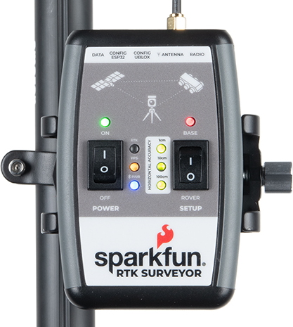
There are a variety of LEDs:
- Power - Blue when attached to power and charging / off when fully charged. Green/Yellow/Red when the Power switch is turned on indicating the state of charge of the internal battery.
- RTK - This white LED will be off when no RTCM correction data is received. Blinking indicates RTK Float is achieved. Solid when RTK Fix is achieved.
- PPS - Pulse per second. This yellow LED will blink at 1Hz when GNSS fix is achieved. You’ll see this LED begin blinking anytime the receiver detects enough satellites to obtain a rough location.
- PAIR - Blinks blue when waiting to be paired with over Bluetooth. Solid when a connection is active.
- Horizontal Accuracy 100cm/10cm/1cm - These green LEDs illuminate as the horizontal positional accuracy increases. 100cm will often be achieved in normal positioning mode with a good L1/L2 antenna. 10cm will often be achieved as the first few seconds of RTCM correction data is received, and 1cm will be achieved when a full RTK fix is calculated.
- BASE - This LED will blink red when the SETUP switch is set to Base and a survey is being conducted. It will turn solid red once the survey is complete and the unit begins broadcasting RTCM correction data.
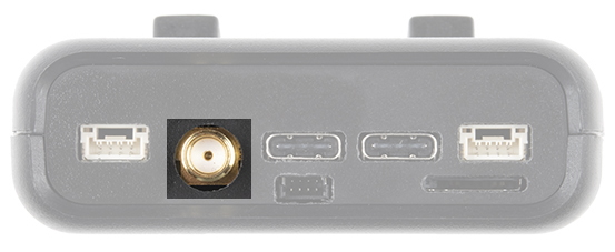
Connectors
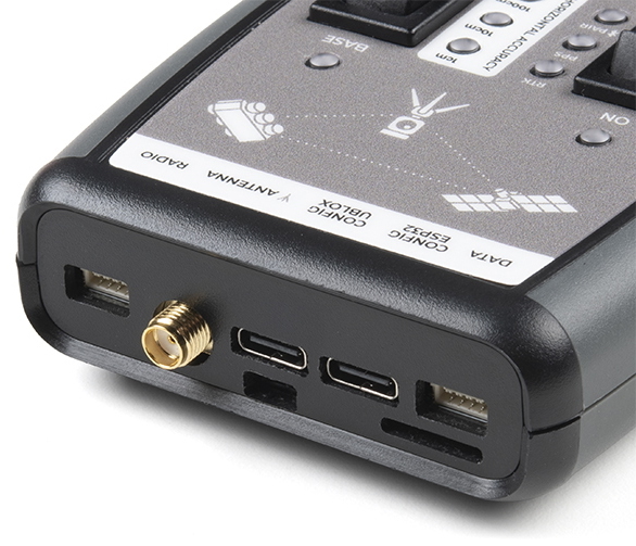
Antenna:
This SMA connector is used to connect an L1/L2 type GNSS antenna to the RTK Surveyor. Please realize that a standard GPS antenna does not receive the L2 band signals and will greatly impede the performance of the RTK Surveyor (RTK fixes are nearly impossible). Be sure to use a proper L1/L2 antenna.
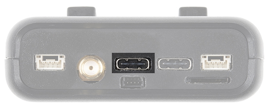
Configure u-blox:
This USB C connector is used for charging the device and/or directly configuring and inspecting the ZED-F9P GNSS receiver using u-center. It’s not necessary in normal operation but is handy for tailoring the receiver to specific applications. As an added perk, the ZED-F9P can be detected automatically by some mobile phones and tablets. If desired, the receiver can be directly connected to a compatible phone or tablet removing the need for a Bluetooth connection.
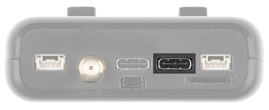
USB Configure ESP32:
This USB C connector is used for charging the device, configuring the device, and reprogramming the ESP32. Various debug messages are printed to this port at 115200bps and a serial menu can be opened to configure advanced settings.
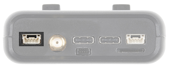
Radio:
This 4-pin JST connector is used to allow RTCM correction data to flow into the device when it is acting as a rover or out of the device when it is acting as a base. You will most likely connect this port to one of our Serial Telemetry Radios using a JST-GHR-04V to JST-GHR-06V Cable (1.25mm pitch) if you don’t have access to a correction source on the Internet. The pinout is 3.5-5.5V / TX / RX / GND. The connector is a 4-pin locking 1.25mm JST SMD connector (part#: SM04B-GHS-TB, mating connector part#: GHR-04V-S). 3.5V to 5.5V is provided by this connector to power a radio with a voltage that depends on the power source. If USB is connected to the RTK Surveyor then voltage on this port will be 5V (+/-10%). If running off of the internal battery then voltage on this port will vary with the battery voltage (3.5V to 4.2V depending on the state of charge). While the port is capable of sourcing up to 2 amps, we do not recommend more than 500mA. This port should not be connected to a power source.
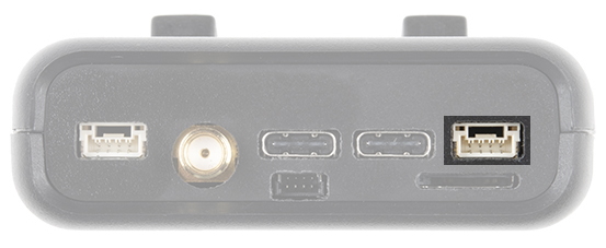
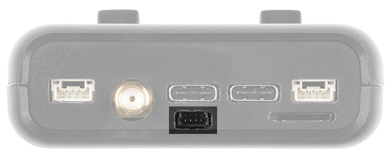
Data:
This 4-pin JST connector is used to output NMEA sentences over 115200bps serial. Most applications will send the NMEA position data over Bluetooth. Alternatively, this port can be useful for sending position data to an embedded microcontroller or single board computer. The pinout is 3.3V / TX / RX / GND. The connector is a 4-pin locking 1.25mm JST SMD connector (part#: SM04B-GHS-TB, mating connector part#: GHR-04V-S). 3.3V is provided by this connector to power a remote device if needed. While the port is capable of sourcing up to 600mA, we do not recommend more than 300mA. This port should not be connected to a power source.
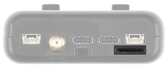
microSD:
This slot accepts standard microSD cards up to 32GB formatted for FAT16 or FAT32. Logging NMEA and RAWX data at up to 4Hz is supported for all constellations.
Qwiic:
This 4-pin Qwiic connector exposes the I2C bus of the ESP32 WROOM module. Currently, there is no firmware support for adding I2C devices to the RTK Surveyor but support may be added in the future.
Power
The RTK Surveyor has a built in 1000mAh battery and consumes approximately 240mA worst case with Bluetooth connection active, GNSS fully tracking, and a 500mW radio broadcasting. This will allow for 4 hours of use in the field. If more time is needed in the field a standard USB power bank can be attached. If a 10,000mAh bank is attached one can estimate 30 hours of run time assuming 25% is lost to efficiencies of the power bank and charge circuit within RTK Surveyor.
The RTK Surveyor can be charged from any USB port or adapter. The charge circuit is rated for 1000mA so USB 2.0 ports will charge at 500mA and USB 3.0+ ports will charge at 1A.
To quickly view the state of charge, turn on the unit. A green LED indicates > 50% charge remaining. A yellow LED indicates > 10% charge remaining. A red LED indicates less than 10% charge remaining.