SparkFun RTK Surveyor Hookup Guide
 Nate, Ell C
Hardware Assembly
The RTK Surveyor was designed to work with low-cost, off the shelf equipment. Here we’ll describe how to assemble a Rover and Base.
Rover
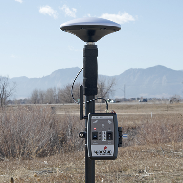
Shown here is the most common RTK Rover setup. A monopole designed for cameras is used. A cell phone holder is clamped to the monopod and the RTK Surveyor is mounted. The ¼” camera thread of the monopole is adapted to ⅝” 11-TPI and a L1/L2 antenna is attached. A Male TNC to Male SMA cable connects the antenna to the RTK Surveyor. No radio is needed because RTCM correction data is provided by a phone over Bluetooth.
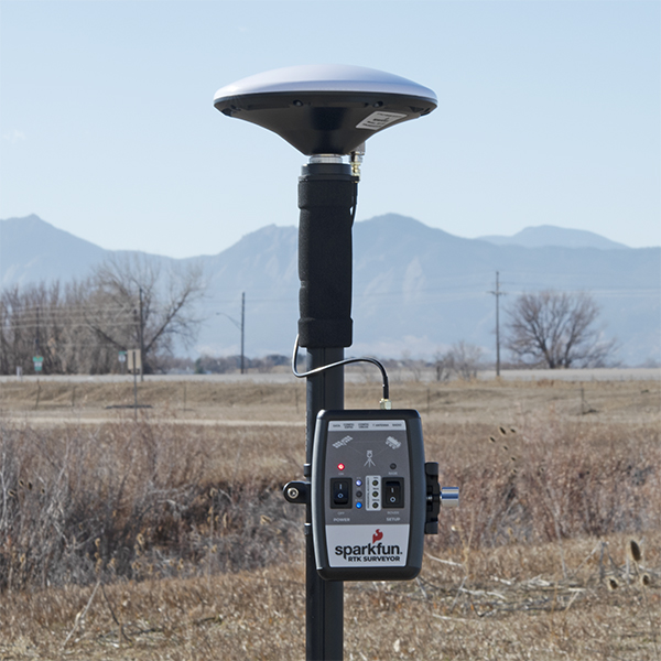
We have done lots of testing with the u-blox L1/L2 antenna and it's very good for the price and size. Mounted to a ground plate you will get good results. It's just a bit ungainly when mounted to the top of a monopole. We recommend the 'ufo' style L1/L2 antennas because they have a larger antenna element and a slightly larger ground plane than the u-blox antenna.
If you’re shopping for a monopole (aka monopod), get one that is 65” in length or greater to ensure that the antenna will be above your head. We’ve had good luck with the Amazon Basics brand.

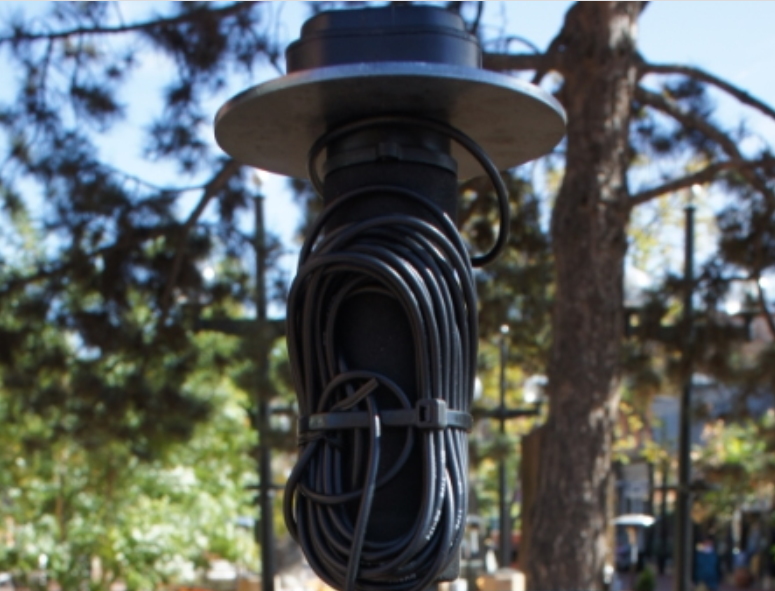
We strongly recommend against using a rigid helical antenna configuration as shown below. The RTK Surveyor is not designed for such configurations and can lead to permanent damage to the antenna connector. The helical antenna becomes a large lever arm. If the unit is dropped this lever is capable of damaging both the SMA connector and where the connector is soldered to the PCB.
If you’re shopping for a cell phone clamp be sure to get one that is compatible with the diameter of your monopole and has a knob to increase clamp pressure. Our monopole is 27mm in diameter and we’ve had a good experience with this clamp and this clamp. Your mileage may vary.
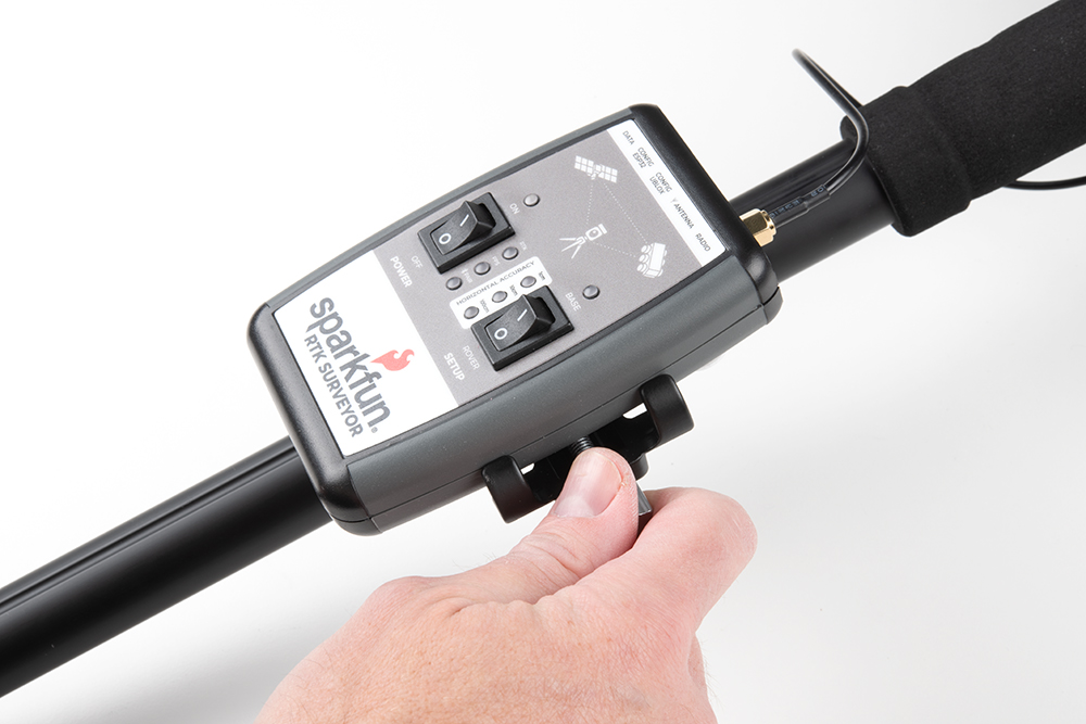
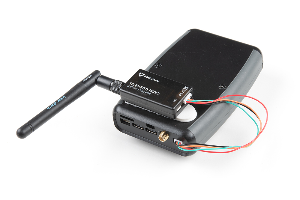
If you are receiving RTCM correction data over a radio link it’s recommended that you attach a radio to the back of the RTK Surveyor.
Picture hanging strips from 3M make a nice semi-permanent mount. Plug the 4-pin to 6-pin JST cable included with the RTK Surveyor from the Radio port to either of the Serial Telemetry Radios (shipped in pairs). We really love these radios because they are paired out of the box, either can send or receive (so it doesn't matter which radio is attached to base or rover) and they have remarkable range. We achieved over a mile range (nearly 1.5 miles or 2.4km) with the 500mW radios and a big 915MHz antenna on the base (see this tutorial for more info).
Temporary Base
A temporary or mobile base setup is needed when you are in the field too far away from a correction source and/or cellular reception. A 2nd RTK Surveyor is mounted to a tripod and it is configured to complete a survey-in (aka, locate itself), then begin broadcasting RTCM correction data. This data (~1000 bytes a second) is sent to the user's connected radio of choice. For our purposes, the 915MHz 500mW telemetry radios are used because they provide what is basically a serial cable between our base and rover.
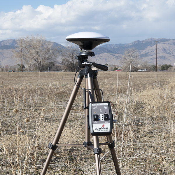
Any tripod with a ¼” camera thread will work. The Amazon Basics tripod works well enough but is a bit light weight and rickety. A cell phone holder is clamped to the tripod and the RTK Surveyor is held in the clamp. The ¼” camera thread is adapted to ⅝” 11-TPI and a L1/L2 antenna is attached. A Male TNC to Male SMA adapter connects the antenna to the RTK Surveyor.
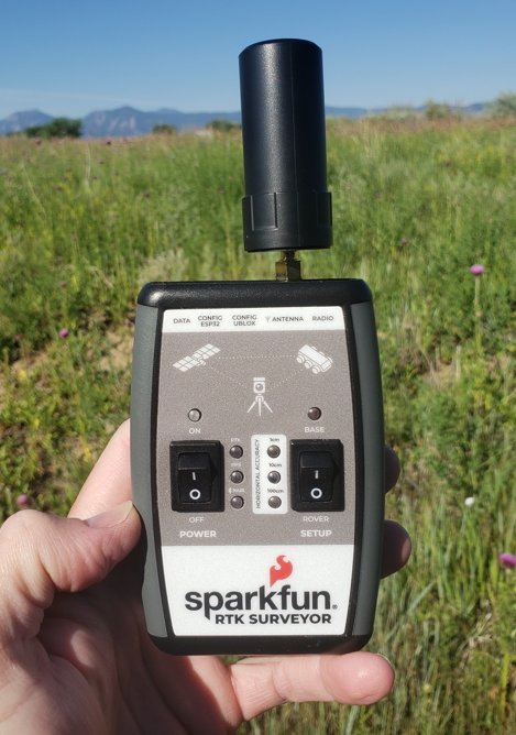
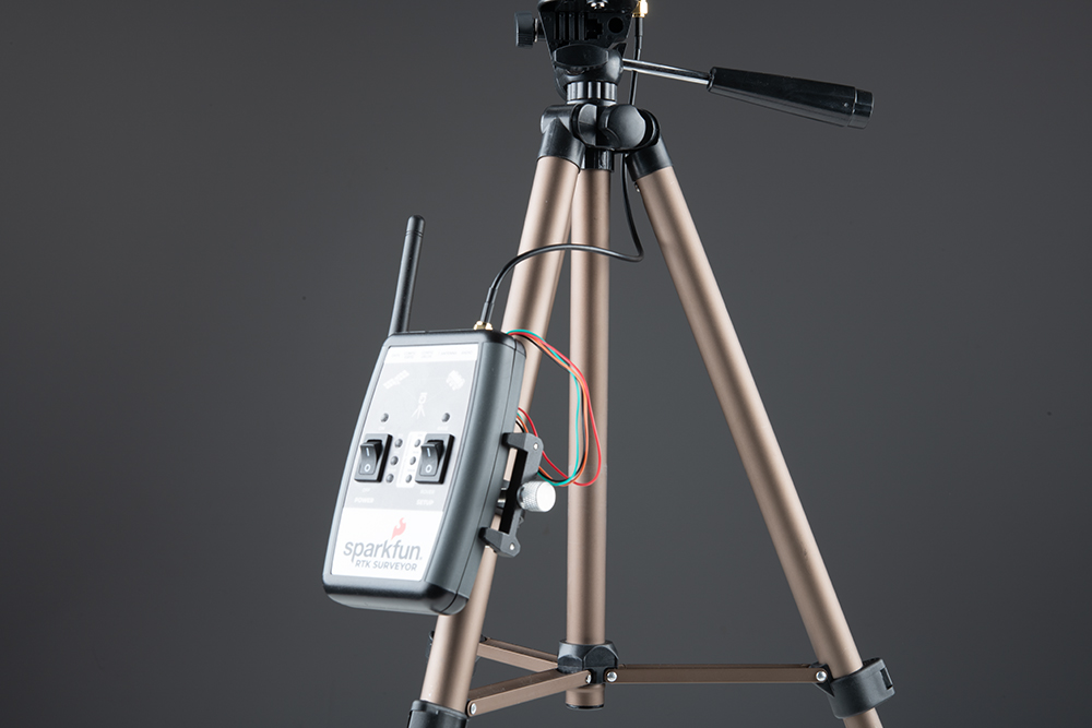
Once the base has been setup with a clear view of the sky, move the Setup switch to "Base" and turn the unit on. The red LED will blink for 60-120 seconds. Once the survey is complete the red LED will be constantly illuminated and RTCM data will begin to be broadcast. You can verify this by viewing the LEDs on the telemetry radio (a small red LED will blink when serial data is received from the RTK Surveyor). The RTK Surveyor is designed to follow the u-blox recommended survey-in of 60s and a mean 3D standard deviation of 5m of all fixes. If a survey fails to achieve these requirements it will auto-restart after 10 minutes.
More expensive surveyor bases have a ⅝” 11-TPI thread but the top of the surveyor base will often interfere with the antenna’s TNC connector. If you chose to use a surveyor’s ‘stick’ be sure to obtain a ⅝” extender plate to raise the antenna at least an inch.
If you’re shopping for a cell phone clamp be sure to get one that is compatible with the diameter of your tripod and has a knob to increase clamp pressure. Our tripod is 18mm in diameter and we’ve had a good experience with this clamp. Your mileage may vary.
Note: A mobile base station works well for quick trips to the field. However, the survey-in method is not recommended for the highest accuracy measurements because the positional accuracy of the base will directly translate to the accuracy of the rover. Said differently, if your base's calulcated position is off by 100cm, so will every reading your rover makes. If you’re looking for maximum accuracy consider installing a static base with fixed antenna. We were able to pinpoint the antenna on the top of SparkFun with an incredible accuracy +/-2mm of accuracy using PPP!