SparkFun RTK Reference Station Hookup Guide
 PaulZC
Hardware Overview
The RTK Reference Station is a fully enclosed, preprogrammed device. There are very few things to worry about or configure but we will cover the basics.
Antenna Connections
Before connecting your Reference Station to a power source, you're going to want to connect it to a couple of antennas.
The rest of the RTK product family use a version of the ESP32-WROOM which has a built-in antenna. The Reference Station does it differently. You need to connect a 2.4GHz WiFi / BT antenna to the ESP32 SMA Reverse Polarity (RP) connector on the rear panel. We included one in the kit. Go ahead and screw it on there!
The GNSS antenna needs to be connected to the standard polarity UBLOX SMA connector. The TNC-SMA cable we included in the kit is of course perfect for the job. If you need a longer cable run, we have good quality RG58 cables available in the store.
microSD Card
Now is a good time to slot the microSD card into place. We included a 32GB card in the kit. Insert it gently into the microSD slot and give it a little push to lock it into place. It is a "push-push" socket. Push it again to release / eject the card.
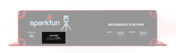
The Reference Station only supports cards formatted as FAT32, which is why we recommend 32GB cards. It does not support exFAT - and most 64GB cards come pre-formatted with exFAT.
If you need to re-format your card at any time, we recommend using the official SD Association Formatter.
Power Options
Unlike the rest of the RTK product family, the Reference Station has no internal battery. It is designed to be "always on". It will start operating as soon as it is connected to a power source. It can operate when powered by any or all of:
- ESP32 USB-C connector
- u-blox GNSS USB-C connector
- Rear USB-C power connector
- Power-over-Ethernet (36V - 57V)
- 5V and GND I/O screw terminals (5.5V DC Maximum)
We included a USB-C wall charger in the kit. Go ahead and plug it in to the rear USB-C power connector to power the system.
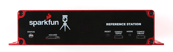
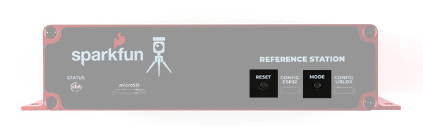
MODE Button
The Reference Station MODE button operates in almost the same way as the SETUP button on the other RTK products.
A single press brings up the mode menu. Press the button again to step through the available modes. Pause on the highlighted mode to select it and change to that mode.
The available modes are:
- BASE Mode
- ROVER Mode
- NTP Mode
- Cfg Eth Configure-Via-Ethernet Mode
- CfgWiFi Configure-Via-WiFi Mode
- E-Pair ESP NOW Pairing
The modes are discussed in a little more detail below and in much more detail in the RTK Product Manual.
BASE Mode is the default as it is the mode we think users will use the most - but you always surprise us with the novel ways you use our products!
A long press of the MODE button will make the Reference Station shut down. Once shut down, only a power cycle or a press of the RESET button will wake it again.
RESET Button
The RESET button is flush with the front sticker. You can still press it with your finger but it takes an assertive press, to prevent accidental resets.
You shouldn't need to press the RESET button often, if at all. Connecting to the ESP32 via USB and opening a serial console, or uploading new firmware, generates a reset automatically. But the RESET button is there if you need it.
STATUS LED
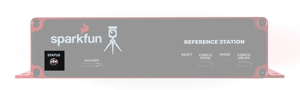
The STATUS LED is used to indicate that all is well with the Reference Station. When lit, the BASE Mode has completed its survey-in.
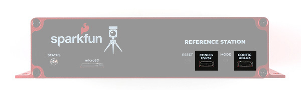
CONFIG ESP32
The CONFIG ESP32 USB-C port provides direct access to the ESP32 Serial port / console. Connect to this from your computer and open a serial terminal at 115200 baud to see diagnostic messages from the RTK firmware. Tera Term is still a good choice for Windows users. Press any key to open the serial configuration menu.
The RTK product range is now able to update its own firmware Over-The-Air (OTA). But you can of course still upload your own code or our pre-compiled firmware binaries onto the ESP32 through this USB-C connection.
CONFIG UBLOX
The CONFIG UBLOX USB-C port provides direct access to the u-blox ZED-F9P GNSS module's USB port. You can use this port to connect to the module using u-blox u-center (we still recommend the original u-center over u-center2). You can also use it to update the ZED-F9P's firmware - either via u-center or using our own u-blox GNSS Firmware Update GUI.
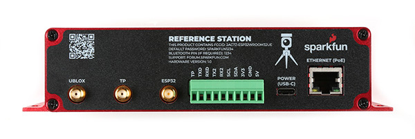
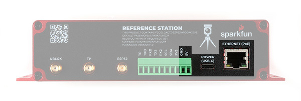
ETHERNET Port
The ETHERNET (PoE) RJ45 Mag Jack port on the rear of the Reference Station is - we hope - self explanatory. It is connected internally to the Power-over-Ethernet module and the WIZnet W5500 Ethernet transceiver. It supports 10/100Mbps communication with auto-negotiation. The mag jack has built-in Link and Activity LEDs. (You can disable these if needed by opening jumper links on the main PCB.) The Power-over-Ethernet module will operate from standard 36V to 57V PoE voltages. Choose a PoE Ethernet Switch that meets your needs. We have had good experiences with the TP-Link TL-SG1005P - available from many retailers including Amazon.
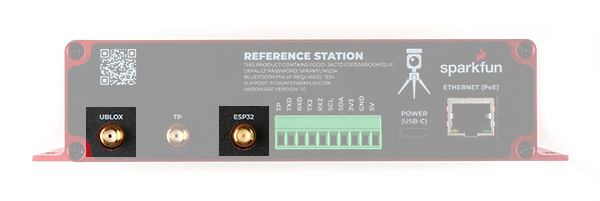
UBLOX SMA Connector
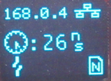
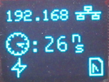
The L1/L2 GNSS antenna included in the kit should be connected to the UBLOX SMA connector using the provided SMA-TNC cable. The Reference Station provides 5V on this connector for an active antenna, instead of the usual 3.3V. The Reference Station also includes both short-circuit and open-circuit detection on this connection. New icons will flash on the OLED display if the antenna is not connected (open) or the cable develops a short.
TP SMA Connector
To try and make the Reference Station more lab-friendly, we connected the ZED-F9P's TP (Timing Pulse, Pulse-Per-Second) pin to a dedicated OpAmp circuit and SMA connector. The default output voltage is 3.3V, but you can select 5V by opening a jumper link on the main PCB. It is not intended to replace your lab signal generator, but it works well up to 100kHz. The unprocessed TP / PPS 3.3V signal is also available on the TP I/O screw terminal. Please see the Product Manual for more details.
ESP32 SMA Connector
The ESP32 WROOM module's u.FL connector is connected to a robust Reverse Polarity (RP) SMA connector. You can screw the provided WiFi / BT antenna directly onto this connector, just like you would with any broadband router. If you want to mount the antenna further away, we have good quality RG58 RP extension cables available in the store.
I/O Screw Terminals
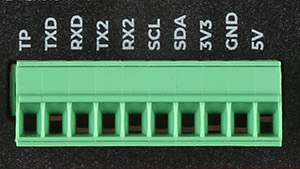
The Reference Station is equipped with a robust 10-way 3.5mm Input / Output screw terminal header. This provides access to the power rails and I/O signals:
- TP : u-blox ZED-F9P GNSS module Timing Pulse (Pulse Per Second): 3.3V OUTPUT
- TXD : ESP32 pin 17 Serial1 (UART) transmit: 3.3V OUTPUT
- The current version of the RTK firmware does not use this pin
- RXD : ESP32 pin 16 Serial1 (UART) receive: 3.3V INPUT
- The current version of the RTK firmware does not use this pin
- TX2 : u-blox ZED-F9P UART2 transmit: 3.3V OUTPUT
- You can connect this pin to a radio module to provide correction data to other Rovers
- RX2 : u-blox ZED-F9P UART2 receive: 3.3V INPUT
- You can connect this pin to a radio module to use correction data provided by another Base
- SCL : ESP32 I2C (Wire / Qwiic) bus clock : 3.3V
- A pull-up is provided on the main PCB. This can be disabled by opening a jumper link
- SDA : ESP32 I2C (Wire / Qwiic) bus data : 3.3V
- A pull-up is provided on the main PCB. This can be disabled by opening a jumper link
- 3V3 : 3.3V power OUTPUT
- This is the internal switched power rail used by the microSD card and WIZnet W5500
- It is enabled by ESP32 pin 32 (PWREN)
- It is disabled when the ESP32 is in reset
- You could use it to power an external radio module or a Qwiic / I2C device
- GND : power GND / 0V
- 5V : 5V power INPUT
- This pin can be used to power the Reference Station from a separate 5V power source
- The maximum voltage is 5.5V DC