SparkFun RTK Reference Station Hookup Guide
 PaulZC
Hardware Overview - Advanced Features
Like most SparkFun products, the RTK Reference Station is completely open source. We're happy to share the full schematic for the main PCB, the Eagle CAD files and the full source code for the firmware. The Reference Station is intended to be another hacker's paradise!
Taking the Reference Station apart is really easy:
- Disconnect all cables
- Unplug the green 10-way 3.5mm I/O connector
- This makes it easy to remove the main PCB from the enclosure
- The connector is a firm fit. You may need to rock it from side to side as you unplug it
- Unscrew the four screws holding the front panel in place
- We recommend removing the front panel first, so you can unplug the OLED display
- Remove the front panel
- Unplug the OLED Qwiic cable
- Slide out the main PCB
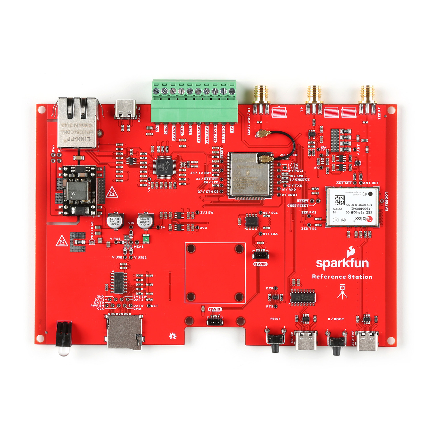
Let's walk you through the main components on the PCB:
ESP32-WROOM
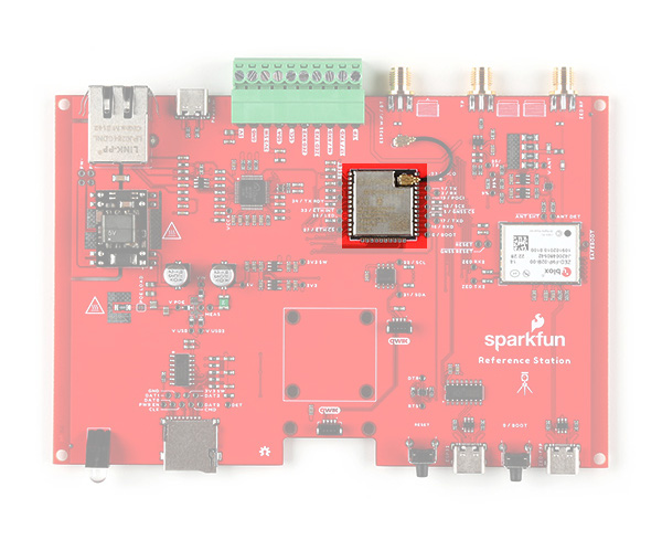
Like the other members of the RTK product family, the RTK Reference Station uses the excellent ESP32-WROOM microcontroller. The only difference here is that we use a version with a built-in u.FL antenna connection. We use a small u.FL cable to connect the ESP32 to the external RP SMA antenna connector.
u-blox ZED-F9P GNSS
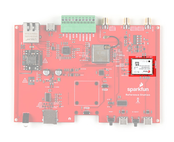
Like most of the RTK product family, the RTK Reference Station uses the excellent ZED-F9P multi-band GNSS module, made by u-blox in Switzerland. We keep using this module because it is phenomenal and we haven't found anything better. The only difference here is that it is connected via SPI, instead of the usual I2C. This provides an order of magnitude improvement in the data transfer speeds.
WIZnet W5500 Ethernet Transceiver
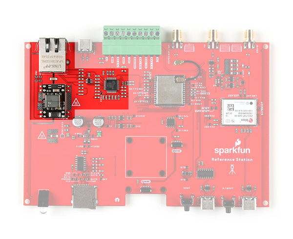
The WIZnet W5500 has been around for years, but it still takes some beating for 10/100Mbps Ethernet applications. We've paired it with a high quality Power-over-Ethernet (PoE) module and shielded RJ45 connector ("mag jack").
Qwiic 1"x1" Footprint
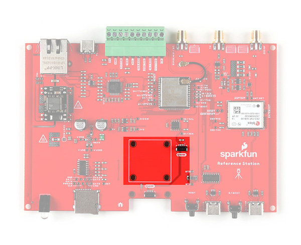
Did we forget to include something? Absolutely not! But we did say that the Reference Station is a hacker's paradise. We've included the 1" x 1" footprint of our standard Qwiic (I2C) sensor boards just in case you want to add your own Inertial Measurement Unit, Pressure Humidity Temperature sensor, battery-backed Real Time Clock or anything else you need for your project. There's a vacant Qwiic connector right there too!
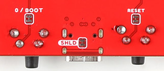
Jumper Links
Like most SparkFun products, the RTK Reference Station PCB has several split-pad jumper links on it, which allow you to configure the board in different ways.
Need to disable all of the LEDs? Not a problem. You will find jumper links for the Link, Activity and Status LEDs. Open them up and leave the OLED display disconnected to blackout your Reference Station.


Need to change the WIZnet W5500 mode? You can do that by configuring the three PMODE jumpers. PMODE0, 1 and 2 are pulled high by default. You can pull them low by soldering the jumpers closed.

There may be times when you want to prevent anyone from pressing the RESET or MODE buttons. There are jumper links for those too. Open them to isolate the two buttons; the ESP32 can then still be reset via the USB-C port and CH340 interface if needed.
To make the Reference Station more lab friendly, we included a SMA connection for the ZED-F9P time pulse (Pulse-Per-Second). The SMA signal is 3.3V by default, but you can change it to 5V by opening the VTP jumper.
