SparkFun RFID Starter Kit Hookup Guide
 a_cavis
Hardware Hookup
Place the ID-12 module onto the RFID USB Reader, and plug the base into your computer with a USB mini-B cable. Depending on your operating system, you may need to install FTDI drivers after plugging in the base station.
Open a terminal program of your choice. If you've never used a terminal program before, here's a guide to choosing and using them.
First, use the Arduino IDE's built-in serial monitor:
- Open the Arduino IDE.
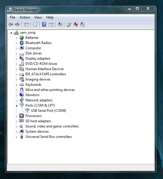
- Go to Tools > Port and select the RFID reader's port.
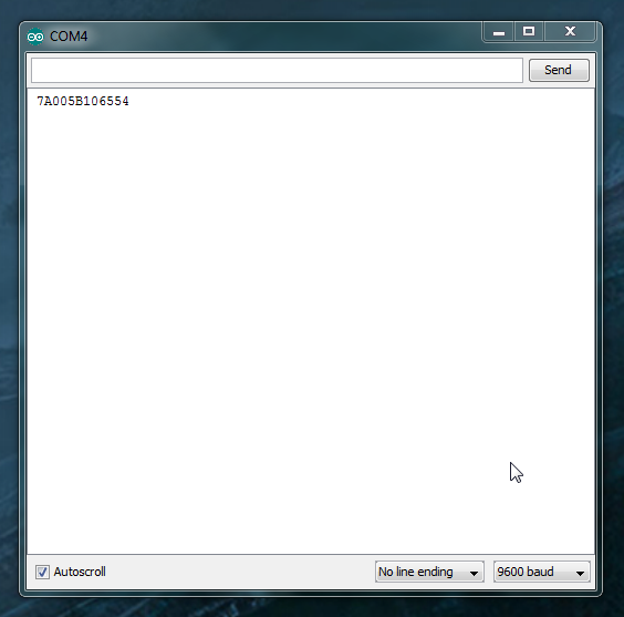
- Go to Tools > Serial Monitor. The default terminal settings (9600 baud, no line ending) are fine. The monitor should be blank.
Wave a card over the reader. You should hear a beep and see something like this.
Now, we'll do the same thing in RealTerm. (Mac users, you can try this section using CoolTerm)
RealTerm may look like the cockpit of a 747 compared to the Arduino serial monitor, but it has several helpful features. Keep the RealTerm tutorial open if you need it.
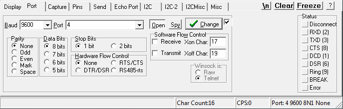
4 and the baud rate to 9600 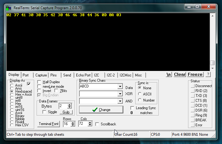
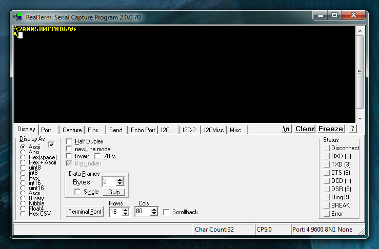
With Display As set to Hex[space], the card data appears as 16 hex bytes instead of 12 ASCII digits like it did in the Arduino Serial Monitor.
Wait, 16 bytes? Where did the extra four come from?
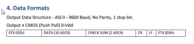
Here's the "Data format" section from the ID-12 module datasheet. The 12 ASCII characters displayed in the Arduino serial monitor are just the filling in a 16-byte sandwich, with four more non-printing characters (STX or start-of-text, CR/carriage return, LF/linefeed, and ETX/end-of-text) as the bread.
Try switching the Display As setting to ASCII and scan again:
Now the "bread" is visible! That's cool, right?