SparkFun RFID Starter Kit Hookup Guide
 a_cavis
Using the RFID Reader Breakout
For Arduino projects, you can also use the SparkFun RFID Reader Breakout which gives the module a place to sit and breaks out its odd 2mm-pitch pins to a breadboard-friendly 0.1" spacing.
To keep the module removable (and protect it from accidental damage during soldering), you can trim 2x 2mm XBee Sockets to size using a diagonal cutter and solder them to the top of the breakout. You will need to sacrifice a header pin when cutting the 2mm XBee socket and pull/clip a pin from the 1x7 header before soldering to the RFID reader breakout as shown in figure 1. Make sure to test the header on the breakout board with the RFID module before soldering.
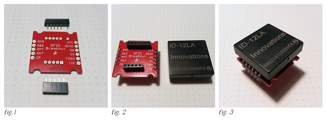
- Fig. 1 XBee sockets trimmed to size with one pin clipped short.
- Fig. 2 Sockets soldered to the top of the breakout with 0.1" male straight header pins on the bottom.
- Fig. 3 Module and breakout ready for use on a breadboard
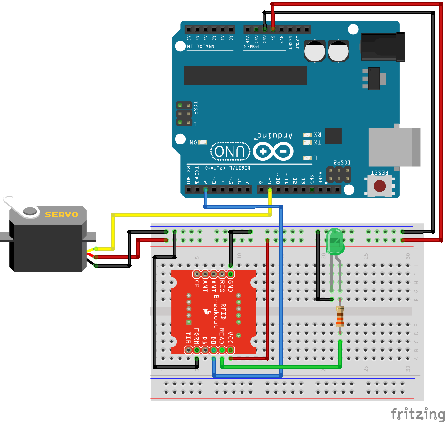
The completed breakout can be used like the larger base station. Here's the same example as above with a green LED and 330 ohm resistor added to the READ pin. TX is labeled D0 on the breakout.