SparkFun Qwiic GPIO Hookup Guide
 El Duderino,
  Englandsaurus
 Introduction
The SparkFun Qwiic GPIO is an I2C device aimed at simplifying adding extra GPIO pins to a microcontroller. The board uses the TCA9534U I/O Expander IC from Texas Instruments to add up to 8 digital inputs and outputs controlled via an I2C interface. The TCA9534U features three address select pins that can be set to configure eight unique addresses meaning you can have up to 64 I/O pins controlled from a single I2C bus!
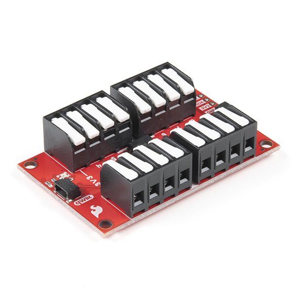
To simplify wiring everything up, we've broken out all eight of the general-purpose I/O pins on the TCA9534U along with several power rail pins to latch terminals and, as you would expect from a Qwiic board, the I2C interface is broken out to a pair of Qwiic connectors.
Controlling the TCA9534 is relatively straightforward but to make things even easier, we've written an Arduino Library and a Python Package for the Qwiic GPIO to make writing code for it as easy as possible.
In this guide we'll go over everything you need to know about the Qwiic GPIO so you can add those extra I/O pins to your circuit with ease!
Required Materials
In order to follow along with this tutorial you'll need a few items along with your Qwiic GPIO. First, you'll need a microcontroller to communicate with the board. Below are a few options that come Qwiic-enabled out of the box:


If your preferred microcontroller does not have a Qwiic connector, you can add one using one of the following products:


Finally, you'll need at least one Qwiic cable and possibly some hook up wire or jumper cables. Below are a few options for each of those cable types:


Qwiic Cable - 200mm
PRT-14428Suggested Reading
If you aren't familiar with the Qwiic system, we recommend reading here for an overview:
We would also recommend taking a look at the following tutorials if you aren't familiar with the concepts covered in them:
Polarity
Serial Terminal Basics
Processor Interrupts with Arduino
How to Work with Jumper Pads and PCB Traces
Hardware Overview
As we mentioned in the Introduction, the Qwiic GPIO features the TCA9534 I/O Expander to communicate with up to eight digital input/output pins via I2C. In this section we'll examine the characteristics of the TCA9534 as well as the features of the Qwiic GPIO breakout.
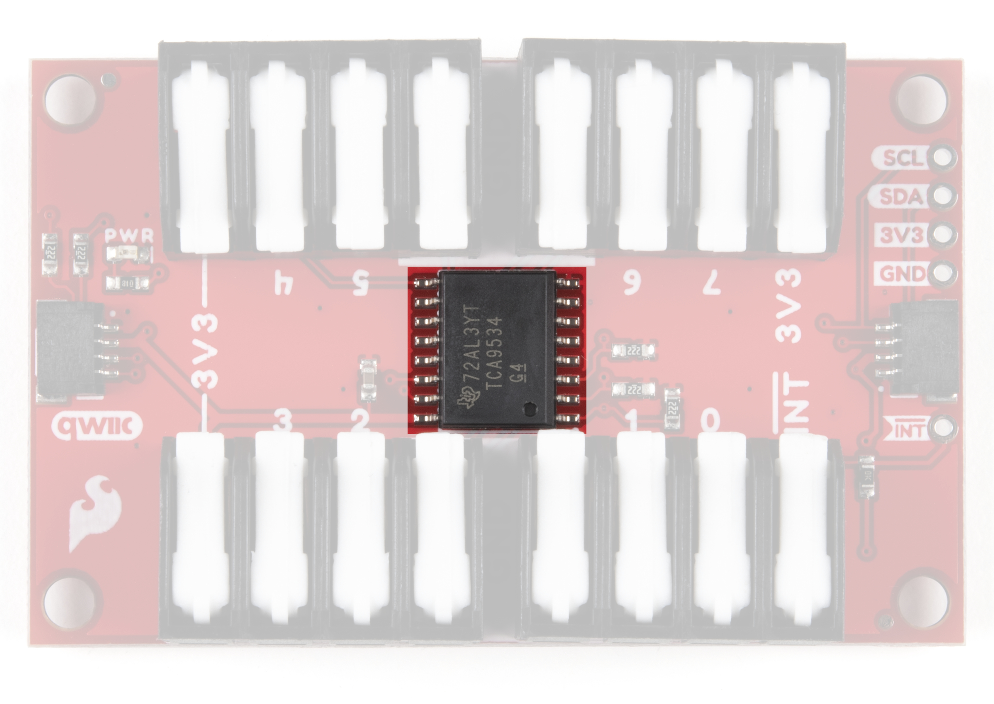
TCA9534 I/O Expander IC
The TCA9534 from Texas Instruments provides an I2C to parallel digital input output interface. We'll cover the basics here but for a thorough overview of the TCA9534 refer to the datasheet. The IC has an operating input voltage range of 1.65V to 5.5V but we recommend powering it with 3.3V via either the Qwiic connector or through any of the 3.3V and Ground pins to maintain compatibility with other Qwiic devices.
The TCA9534 supports both standard (100kHz) and fast mode (400kHz) I2C frequencies. The IC also features an active-low interrupt pin that is activated when any pins configured as an input have a different state from the Input Port register state. This means you can connect this INT pin to an interrupt-capable pin on your microcontroller to passively monitor devices connected to the TCA9534. For more information on this functionality, refer to section 8.3.2 in the TCA9534 datasheet and Example 4 - Interrupt in the Qwiic GPIO Arduino Library.
Three hardware pins (A0, A1 and A2) are dedicated I2C address select pins. We've added three jumpers to the Qwiic GPIO to allow users to have up to 8 boards on the same bus. The Solder Jumpers section below goes into more detail on how those pins and jumpers are used on the Qwiic GPIO.
Latch Terminals
The Qwiic GPIO breaks out all eight of the TCA9534's I/O pins, the interrupt pin, as well as several power rail pins (3.3V and Ground) to four 4-pin latch terminals so wiring peripherals to the board is extremely easy. All you need to do is insert a stripped wire into your preferred terminal opening and press down firmly on the latch handle to secure the wire into place.

Each I/O pin defaults as an input at power on. Sending the appropriate commands will switch them to an output and you can also invert the polarity of each pin as well via I2C. Read on to the Qwiic GPIO Arduino Library and Python package sections for more information on how to configure and interact with these pins.
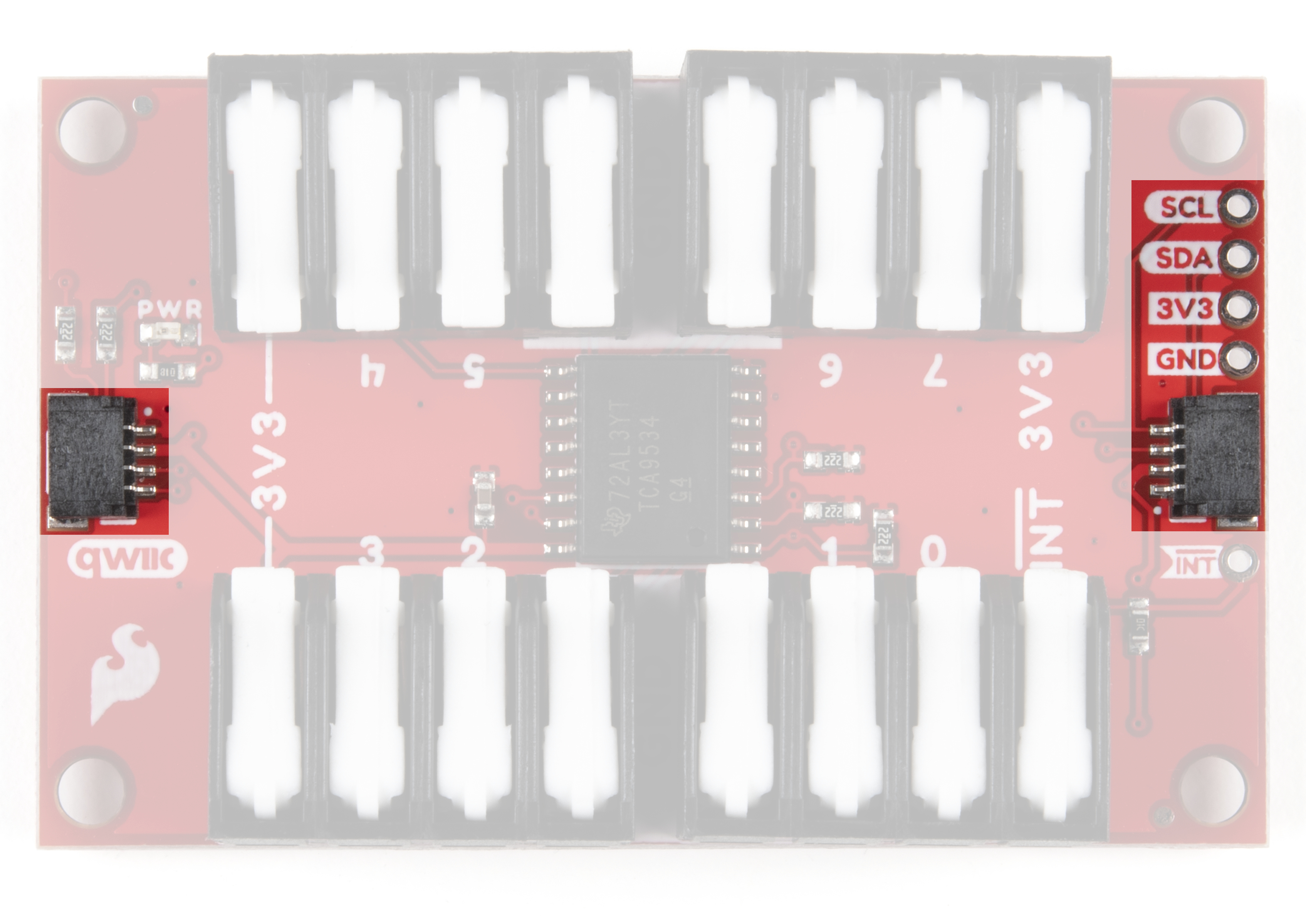
Qwiic and I2C Interface
As you have come to expect with Qwiic boards, the connections for the I2C bus (SDA, SCL, GND and 3.3V) on the Qwiic GPIO are broken out to a pair of Qwiic connectors as well as standard 0.1" spaced PTH pins for those who would prefer to solder to them. The default I2C address for the Qwiic GPIO is 0x27.
Solder Jumpers
The Qwiic GPIO has six solder jumpers to configure the board labeled I2C, PWR, INT, A0, A1 and A2. This section covers what each jumper's functionality is and how to configure them.

I2C Jumper
This jumper ties the SDA and SCL lines to 3.3V via two 4.7kΩ resistors. The default state is closed. To disable the pull-up resistors, simply sever the traces in between the pads to open the jumper. If you have multiple Qwiic GPIO's or other I2C devices on the same bus, disable all but one pair of pull-up resistors to avoid creating too strong of a resistance on the SDA and SCL lines.
Power Jumper
This jumper controls voltage to the power LED on the board. It ties the anode of the power LED to 3.3V via a 1kΩ resistor. The default state is closed. To disable the power LED, open the jumper by severing the trace between the two pads. Disabling the power LED will help reduce overall current consumption of the board.
Interrupt Jumper
This jumper ties the TCA9534's interrupt pin to 3.3V via a 10kΩ resistor and its default state is closed. This holds the Interrupt pin HIGH so it can be driven LOW when an interrupt event is monitored by the TCA9534. Open the jumper if you have another pullup on the Interrupt pin.
Address Jumpers
The three address jumpers on the Qwiic GPIO: ADR0, ADR1 and ADR2, set the I2C address of the TCA9534 by pulling them either to 3.3V or 0V/Ground. The default state of all three jumpers is closed and they tie each address pin to 3.3V via a 2.2kΩ resistor. This configuration sets the default I2C address to 0x27. By opening or closing these jumpers you can alter the address of the TCA9534 so you can have up to eight of these boards on a single I2C bus. Click the button to open the table below showing the various jumper configurations and what I2C address each configuration sets:
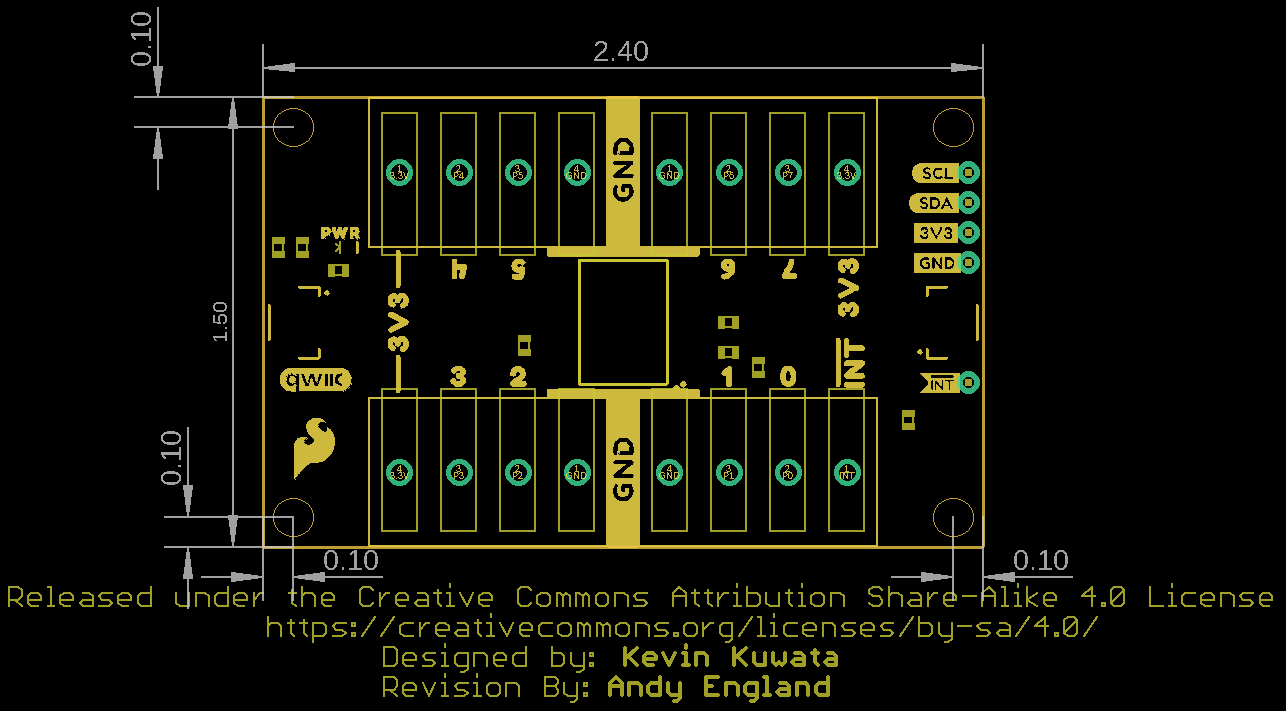
Board Dimensions
The Qwiic GPIO is a bit larger than our standard Qwiic breakout size (1" x 1"). It measures in at 2.40" x 1.50" (60.96mm x 38.10mm) and has four mounting holes that fit a 4-40 screw.
Now that we are more familiar with the hardware present on the Qwiic GPIO it's time to hook it up to our microcontroller and attach some peripherals to the I/O pins. Next up we'll detail how to assemble the board and your Qwiic GPIO circuit.
Hardware Assembly
The Qwiic system makes connecting the Qwiic GPIO to your chosen microcontroller a breeze. All you need to do is connect your Qwiic GPIO to your chosen development board with a Qwiic cable or adapter cable. If you would prefer to not use the Qwiic connectors, you can connect to the 0.1" header pins broken out on the side of the board.
If you prefer to use the PTH pins broken out on the Qwiic GPIO you will need to solder to them. For a temporary connection for prototyping, these IC Hooks are a great option to make that connection. For users not familiar with through-hole soldering take a look at this tutorial:
How to Solder: Through-Hole Soldering
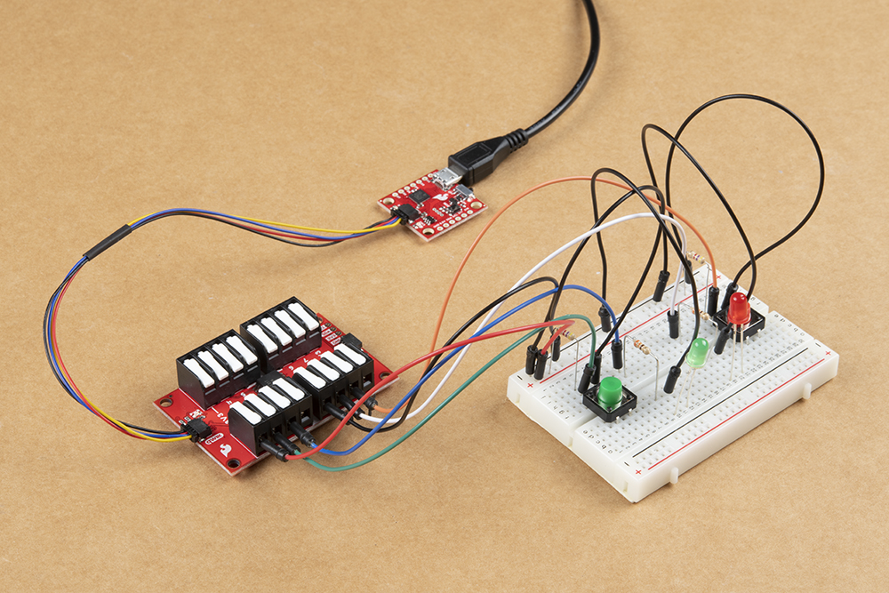
Connecting peripherals to the GPIO is simple as well with the latch terminals. If you are using hook-up wire, make sure you've stripped the end, insert it into the appropriate terminal (making sure it is "open") and then press down on the latch terminal firmly to secure the wire in place. Depending on how you intend to use the I/O pin you'll want to connect your other wire to either a 3.3V or Ground pin. For demonstration purposes, we're using LEDs and buttons to act as our inputs and outputs (respectively).
With the Qwiic GPIO circuit assembled and connected to your microcontroller it's time to get some code uploaded and start controlling the extra I/O pins via I2C!
Qwiic GPIO Arduino Library
The SparkFun Qwiic GPIO Arduino Library helps to make interfacing between the TCA9534 and your Arduino microcontroller simple. In this section we'll list all of the functions available in the library as well as brief descriptions about what they do.
Library Functions
We've outlined all the functions in the Arduino library below along with some quick descriptions of what they do. The examples cover nearly all of the functions so you may want to refer to those for help with writing your own code using them.
Device Setup & Settings
bool begin(TwoWire &wirePort, uint8_t address);- Initialize the TCA9534 on the I2C bus. If you have set the TCA9534 to an alternate I2C address using the ADR jumpers, enter that here.bool pinMode(uint8_t gpioNumber, bool mode);- Sets the mode of the selected GPIO pin on the TCA9534. For example,pinMode(0, GPIO_OUT);sets pin 0 as an output. All I/O's default to Inputs on power up.bool pinMode(bool *gpioPinMode);- An alternative to the above function to set the entire port as an input or output. This accepts a bool defined in your setup to set all eight GPIO pins at once. Refer to Example1B - Write_GPIO_Port for more information on using this function.bool invertPin(uint8_t gpioNumber, bool inversionMode);- Invert the polarity of the selected GPIO pin on the TCA9534.bool invertPin(bool *inversionMode);- Invert the polarity of the entire port of the TCA9534. Refer to Example 3B - Inversion_Port for a demonstration of how to set up and use this function.
GPIO Reading and Writing
bool digitalWrite(uint8_t gpioNumber, bool value);- Your basic Digital Write function. Write to the selected GPIO pin eitherHIGHorLOW.bool digitalWrite(bool *gpioOutStatus);- Write to the entire port set up using aboolto eitherHIGHorLOW.bool digitalRead(uint8_t gpioNumber);- Standard Digital Read function. Returns the status of the selected GPIO pin.uint8_t digitalReadPort(bool *gpioInStatus);- Read the status of the entire port set up using abool. Returns status of all selected pins on the port. Take a look at Example2B - Read_GPIO_Port for reference.
Advanced Functions
These functions are intended for experienced users to write and read specific bits and registers.
bool readBit(uint8_t regAddr, uint8_t bitAddr);- Read a specific bit in a selected register.bool writeBit(uint8_t regAddr, uint8_t bitAddr, bool bitToWrite);- Write to a specific bit in a selected register.uint8_t readRegister(uint8_t addr);- Read a specific register.bool writeRegister(uint8_t addr, uint8_t val);- Write to a specific register.
Next up we'll cover the examples included with the Qwiic GPIO Arduino library to see these functions in action along with explaining a bit more on how to set up the port options for pinMode();, invertPin(); and digitalWrite();.
Arduino Examples
The Qwiic GPIO Arduino Library has three examples split into single pin and port variants to demonstrate how to set up control the TCA9534 along with a fourth example demonstrating how to use the external interrupt capability. In this section we will go over those examples and highlight a few things to take note of when setting up your Qwiic GPIO in code.
#define Serial SerialUSB
This definition helps a ton when working with chip architectures that have multiple serial ports you need to call specifically instead of using a general
Serial calls. Simply update that definition with whichever serial port you want to use for serial prints via USB.
Example 1A: Write GPIO
A basic digital write example. Open Example 1A in Arduino by navigating to File > Examples > SparkFun Qwiic GPIO Arduino Library > Example1a-Write_GPIO. This example sets up GPIO 0 as an output and toggles it HIGH and LOW. The code starts up by initializing the Qwiic GPIO on the I2C bus on the default address and sets GPIO0 as an output:
language:c
myGPIO.pinMode(0, GPIO_OUT); //Use GPIO_OUT and GPIO_IN instead of OUTPUT and INPUT_PULLUP
Take note to use GPIO_OUT or GPIO_IN instead of the standard Arduino setup of OUTPUT and INPUT_PULLUP when setting the GPIO pin as an input or output. We use these alternates because the TCA9534's I/O pins default as an INPUT (pin mode = True) so GPIO_IN = true and GPIO_OUT = false are defined in the library to set the pin mode to avoid confusion. After we've set up GPIO 0 as an output, the code toggles it HIGH and LOW using digitalWrite(); every second and prints out the GPIO status via serial.
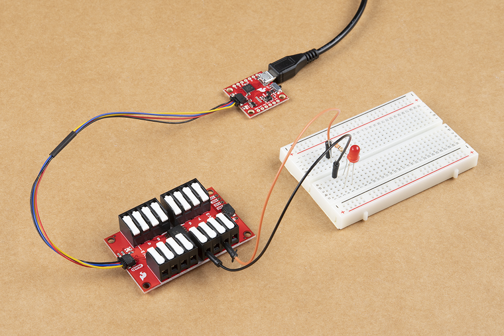
The demo circuit above shows a visual representation of GPIO 0 being toggled HIGH and LOW using an LED. If you want to control more pins, simply add another myGPIO.pinMode(); for whichever pin you want to use to set it as an output and then control it using myGPIO.digitalWrite();.
Example 1B: Write GPIO - Port
This version of writing to the Qwiic GPIO controls the entire port (all eight GPIO pins). In order to set up the port we need to define the number of GPIO pins we are using as well as construct a boolean to define each pin as either an input or output. Since this example is for writing to the port, all eight pins are defined as outputs:
language:c
#define NUM_GPIO 8

bool currentPinMode[NUM_GPIO] = {GPIO_OUT, GPIO_OUT, GPIO_OUT, GPIO_OUT, GPIO_OUT, GPIO_OUT, GPIO_OUT, GPIO_OUT};
Along with the pin mode, we also need to define the initial state of each GPIO:
language:c
bool gpioConfig[NUM_GPIO] = {HIGH, LOW, HIGH, LOW, HIGH, LOW, HIGH, LOW}
With the GPIO port configured, the code initializes the Qwiic GPIO on the I2C bus and then alternates the state of each pin every second using a function specific to this example called flipGPIO();:
language:c
void flipGPIO()
{
    for (uint8_t arrayPosition = 0; arrayPosition < NUM_GPIO; arrayPosition++)
    {
        gpioConfig[arrayPosition] = !gpioConfig[arrayPosition];
    }
}
Example 2A: Read GPIO
Example 2A demonstrates how to read an individual GPIO pin on the TCA9534. It starts by setting up GPIO 0 as an input, reads its state and prints out whether it is HIGH or LOW via serial. Similar Example 1, GPIO 0 is set up but in this case is set as an input using pinMode(0, GPIO_IN);. The code then monitors the pin's state every 250ms and prints the state via serial. You can view the main loop below:
language:c
void loop() {
  bool gpioState = myGPIO.digitalRead(0);
  switch (gpioState) {
    case true:
      Serial.println("HIGH");
      break;
    case false:
      Serial.println("LOW");
      break;
  }
  delay(250);
}
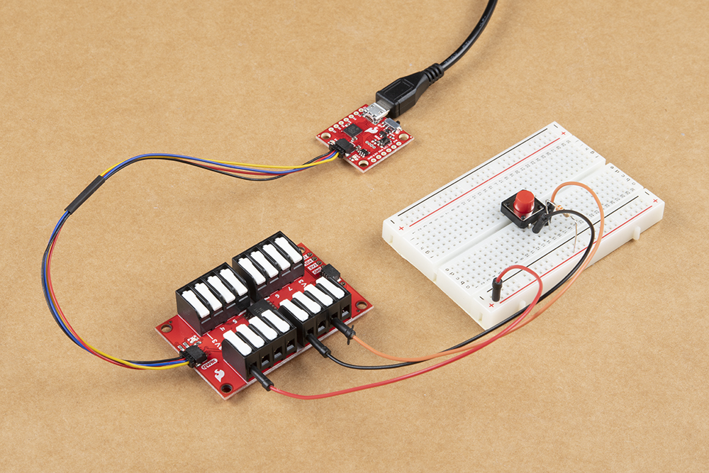
The example circuit pictured above demonstrates how to monitor an active HIGH input on the Qwiic GPIO by driving the selected I/O pin (in this case GPIO 0) LOW whenever the button is pressed.
Example 2B: Read GPIO - Port
Example 2B demonstrates how to read the entire GPIO port on the TCA9534. The code sets up all eight GPIO pins just like Example 1B using a boolean but this time all pins are set as inputs. We also need to set up a second boolean for the GPIO pin status due to how the port read register of the TCA9534 works:
language:c
bool gpioStatus[NUM_GPIO]
With the port set up and configured, we can move on to initializing the Qwiic GPIO on the I2C bus and start reading the status of the entire GPIO port. As the comment in the code below explains, in order to read from the port you can either return the full register value as an unsigned 8-bit integer or by passing an array of 8 booleans modified by the function that returns the status of each pin. The example defaults to the latter and sets up an array for the port read:
language:c
void loop() {
  //There are two ways to read from a port, either by returning the full register value as a uint8_t, or passing in an array of 8 boolean's to be modified by the function with the statuses of each pin
  uint8_t portValue = myGPIO.digitalReadPort(gpioStatus);

  Serial.print("uint8_t: ");
  Serial.println(portValue, BIN);
  Serial.print("Bool array: ");
  for (uint8_t arrayPosition = 0; arrayPosition < NUM_GPIO; arrayPosition++) {
    Serial.print(arrayPosition);
    Serial.print(": ");
    switch (gpioStatus[arrayPosition])
    {
      case true:
        Serial.print("HIGH");
        break;
      case false:
        Serial.print("LOW");
        break;
    }
  }
  Serial.println("\n");
  delay(100);
}
Example 3A: Inversion
Example 3A shows how to invert the signal polarity of an input on the Qwiic GPIO. Polarity inversion only works on pins configured as an input so first we set the pin mode and then we invert the polarity. Input pins default to active HIGH so inverting it changes it to active LOW. Below you can see the setup required for pin inversion:
language:c
myGPIO.pinMode(0, GPIO_IN);
myGPIO.invertPin(0, INVERT);
Once we have set up the pin as an input and inverted the polarity the main loop reads the status of the pin every 100ms:
language:c
void loop() {
  bool status = myGPIO.digitalRead(0);
  switch (status)
    {
      case true:
        Serial.println("GPIO 0: HI");
        break;
      case false:
        Serial.println("GPIO 0: LO");
        break;
    }
  delay(100);
}
Example 3B: Inversion - Port
Example 3B, as you might expect by now, exhibits how to invert the entire port on the Qwiic GPIO. The code starts as the other port examples do by defining the number of pins and setting the pin mode of all pins on the port. It then inverts half of the pins' polarity using a second boolean. The setup can be seen below:
language:c
#define NUM_GPIO 8

bool currentPinMode[NUM_GPIO] = {GPIO_IN, GPIO_IN, GPIO_IN, GPIO_IN, GPIO_IN, GPIO_IN, GPIO_IN, GPIO_IN};

bool inversionStatus[NUM_GPIO] = {INVERT, INVERT, INVERT, INVERT, NO_INVERT, NO_INVERT, NO_INVERT, NO_INVERT};
The main loop is identical to Example 2B - ReadGPIO - Port and prints out the state of the port register using an unsigned 8-bit integer.
Example 4: Interrupt
#define INTERRUPT PIN 13 to the selected pin. If you are not familiar with using processor interrupts on a microcontroller, this tutorial will help you get started.Example 4 demonstrates how to use the interrupt pin on the TCA9534 when any input pin registers a change. The interrupt pin is active LOW and will return to HIGH once the input register is read. We've broken the INT pin out to a latch terminal so you can connect a wire to that terminal and tie it to the interrupt-capable pin on your microcontroller. If you prefer, the INT pin is also broken out to a PTH pin you can solder to. Whichever option you choose, connect the interrupt pin on your Qwiic GPIO to D13 on your Arduino (assuming you are using an Uno/RedBoard).
The code starts similarly to our other Port examples by defining the number of GPIO pins and setting their pin status. Along with the GPIO pins, we define the interrupt pin on our microcontroller. You can view the pertinent bits of this code below:
language:c
#define NUM_GPIO 8

#define INTERRUPT_PIN 13

bool currentPinMode[NUM_GPIO] = {GPIO_IN, GPIO_IN, GPIO_IN, GPIO_IN, GPIO_IN, GPIO_IN, GPIO_IN, GPIO_IN};

bool gpioStatus[NUM_GPIO];

bool dataReady = true;
With everything defined, the setup initializes the Qwiic GPIO on the I2C bus, sets the interrupt pin on the microcontroller as an input, "primes" it by writing it HIGH and tells our microcontroller to treat it as an interrupt:
language:c
pinMode(INTERRUPT_PIN, INPUT_PULLUP);
digitalWrite(INTERRUPT_PIN, HIGH);
attachInterrupt(digitalPinToInterrupt(INTERRUPT_PIN), ISR, FALLING);
Now that our interrupt pin is configured the code monitors the GPIO pins' statuses and any time the status changes, the interrupt pin on the Qwiic GPIO will be driven LOW. You can view the entire loop and ISR function below:
language:c
void loop() {
  if (dataReady) {
    myGPIO.digitalReadPort(gpioStatus);
    for (uint8_t arrayPosition = 0; arrayPosition < NUM_GPIO; arrayPosition++) {
      Serial.print(arrayPosition);
      Serial.print(": ");
      switch (gpioStatus[arrayPosition])
      {
        case true:
          Serial.print("HI ");
          break;
        case false:
          Serial.print("LO ");
          break;
      }
    }
    Serial.println();
    dataReady = false;
  }
}

void ISR() {
  dataReady = true;
}
That wraps up the Arduino examples but if you would prefer to use Python instead with a different development board or single-board computer like the Raspberry Pi, read on to the next two sections where we'll detail how to use the Qwiic GPIO Python Package.
Qwiic GPIO Python Package
Note: This package assumes you are using the latest version of Python 3. If this is your first time using Python or I2C hardware on a Raspberry Pi, please checkout our tutorial on Python Programming with the Raspberry Pi and the Raspberry Pi SPI and I2C Tutorial.
Along with the Arduino Library, we've written a Python package to control the Qwiic GPIO. You can install the sparkfun-qwiic-gpio Python package hosted by PyPi or if you prefer to manually download and build the libraries from the GitHub repository, you can grab them by clicking the button below (*Please be aware of any package dependencies. You can also check out the repository documentation page, hosted on Read the Docs.):
Installation
Note: Don't forget to double check that the hardware I2C connection is enabled on your Raspberry Pi or other single board computer.
PyPi Installation
This repository is hosted on PyPi as the sparkfun-qwiic-gpio package. On systems that support PyPi installation via pip3 (use pip for Python 2) is simple using the following commands:
For all users (note: the user must have sudo privileges):
language:bash
sudo pip3 install sparkfun-qwiic-gpio
For the current user:
language:bash
pip3 install sparkfun-qwiic-gpio
Local Installation
To install, make sure the setuptools package is installed on the system.
Direct installation at the command line (use python for Python 2):
language:bash
python3 setup.py install
To build a package for use with pip3:
language:bash
python3 setup.py sdist
A package file is built and placed in a subdirectory called dist. This package file can be installed using pip3.
language:bash
cd dist
pip3 install sparkfun_qwiic_gpio-<version>.tar.gz
Dependencies
This Python package has a few dependencies in the code, listed below:
language:python
from __future__ import print_function
import math
import qwiic_i2c
Function Overview
For a full overview of all the functions included with the Qwiic GPIO Py package, head on over to the ReadtheDocs page.
Python Examples
With the Qwiic GPIO Python Package installed, we can start working with the examples included with it. In this section we'll go over each example and highlight pertinent bits of code. To run the examples, download or copy the code into a file then open/save the example file (if needed) and execute the code in your preffered Python IDE.
Qwiic GPIO Example 1
This example sets up all eight I/O pins as outputs and toggles them on and off each second. Note you need to define the mode of each pin as well as call setMode to write the configuration to the Qwiic GPIO. Copy the code below and execute it in your chosen Python IDE.
language:python
from __future__ import print_function
import qwiic_gpio
import time
import sys

def runExample():

    print("\nSparkFun Qwiic GPIO Example 1\n")
    myGPIO = qwiic_gpio.QwiicGPIO()

    if myGPIO.isConnected() == False:
        print("The Qwiic GPIO isn't connected to the system. Please check your connection", \
            file=sys.stderr)
        return

    myGPIO.begin()
    myGPIO.mode_0 = myGPIO.GPIO_OUT
    myGPIO.mode_1 = myGPIO.GPIO_OUT
    myGPIO.mode_2 = myGPIO.GPIO_OUT
    myGPIO.mode_3 = myGPIO.GPIO_OUT
    myGPIO.mode_4 = myGPIO.GPIO_OUT
    myGPIO.mode_5 = myGPIO.GPIO_OUT
    myGPIO.mode_6 = myGPIO.GPIO_OUT
    myGPIO.mode_7 = myGPIO.GPIO_OUT
    myGPIO.setMode()

    while True:
        myGPIO.out_status_0 = myGPIO.GPIO_HI
        myGPIO.out_status_1 = myGPIO.GPIO_HI
        myGPIO.out_status_2 = myGPIO.GPIO_HI
        myGPIO.out_status_3 = myGPIO.GPIO_HI
        myGPIO.out_status_4 = myGPIO.GPIO_HI
        myGPIO.out_status_5 = myGPIO.GPIO_HI
        myGPIO.out_status_6 = myGPIO.GPIO_HI
        myGPIO.out_status_7 = myGPIO.GPIO_HI
        myGPIO.setGPIO()
        print("set hi")
        time.sleep(1)
        myGPIO.out_status_0 = myGPIO.GPIO_LO
        myGPIO.out_status_1 = myGPIO.GPIO_LO
        myGPIO.out_status_2 = myGPIO.GPIO_LO
        myGPIO.out_status_3 = myGPIO.GPIO_LO
        myGPIO.out_status_4 = myGPIO.GPIO_LO
        myGPIO.out_status_5 = myGPIO.GPIO_LO
        myGPIO.out_status_6 = myGPIO.GPIO_LO
        myGPIO.out_status_7 = myGPIO.GPIO_LO
        myGPIO.setGPIO()
        print("set lo")
        time.sleep(1)


if __name__ == '__main__':
    try:
        runExample()
    except (KeyboardInterrupt, SystemExit) as exErr:
        print("\nEnding Example 1")
        sys.exit(0)
Qwiic GPIO Example 2
Example 2 shows how to read each I/O pin when they are configured as inputs. It first sets up all pins using the setMode function as we did in Example 1. The code then monitors and prints out the status of each input every 0.25 seconds. You can copy the entire example below or open it from your downloaded copy of the Python package:
language:python
from __future__ import print_function
import qwiic_gpio
import time
import sys


def runExample():

    print("\nSparkFun Qwiic GPIO Example 2\n")
    myGPIO = qwiic_gpio.QwiicGPIO()

    if myGPIO.isConnected() == False:
        print("The Qwiic GPIO isn't connected to the system. Please check your connection",
              file=sys.stderr)
        return

    myGPIO.begin()
    myGPIO.mode_0 = myGPIO.GPIO_IN
    myGPIO.mode_1 = myGPIO.GPIO_IN
    myGPIO.mode_2 = myGPIO.GPIO_IN
    myGPIO.mode_3 = myGPIO.GPIO_IN
    myGPIO.mode_4 = myGPIO.GPIO_IN
    myGPIO.mode_5 = myGPIO.GPIO_IN
    myGPIO.mode_6 = myGPIO.GPIO_IN
    myGPIO.mode_7 = myGPIO.GPIO_IN
    myGPIO.setMode()

    while True:
        myGPIO.getGPIO() #This function updates each in_status_x variable
        print("GPIO 0:", end=" ")
        print(myGPIO.in_status_0, end=" ")
        print("GPIO 1:", end=" ")
        print(myGPIO.in_status_1, end=" ")
        print("GPIO 2:", end=" ")
        print(myGPIO.in_status_2, end=" ")
        print("GPIO 3:", end=" ")
        print(myGPIO.in_status_3, end=" ")
        print("GPIO 4:", end=" ")
        print(myGPIO.in_status_4, end=" ")
        print("GPIO 5:", end=" ")
        print(myGPIO.in_status_5, end=" ")
        print("GPIO 6:", end=" ")
        print(myGPIO.in_status_6, end=" ")
        print("GPIO 7:", end=" ")
        print(myGPIO.in_status_7)
        time.sleep(.25)

if __name__ == '__main__':
    try:
        runExample()
    except (KeyboardInterrupt, SystemExit) as exErr:
        print("\nEnding Example 1")
        sys.exit(0)
Qwiic GPIO Example 3
Example 3 demonstrates how to invert an I/O pin configured as an input. We first set all eight pins as inputs and then invert half of them using the setInversion(self) function. As we covered in the Arduino Examples section, each I/O pin set as an input defaults to an active HIGH input so inverting it switches it to an active LOW input. Again, note that you need to define the inversion status of each pin you wish to invert and then write that data using the setInversion function.
language:python
from __future__ import print_function
import qwiic_gpio
import time
import sys


def runExample():

    print("\nSparkFun Qwiic GPIO Example 3\n")
    myGPIO = qwiic_gpio.QwiicGPIO()

    if myGPIO.isConnected() == False:
        print("The Qwiic GPIO isn't connected to the system. Please check your connection",
              file=sys.stderr)
        return

    myGPIO.begin()
    myGPIO.mode_0 = myGPIO.GPIO_IN
    myGPIO.mode_1 = myGPIO.GPIO_IN
    myGPIO.mode_2 = myGPIO.GPIO_IN
    myGPIO.mode_3 = myGPIO.GPIO_IN
    myGPIO.mode_4 = myGPIO.GPIO_IN
    myGPIO.mode_5 = myGPIO.GPIO_IN
    myGPIO.mode_6 = myGPIO.GPIO_IN
    myGPIO.mode_7 = myGPIO.GPIO_IN
    myGPIO.setMode()

    myGPIO.inversion_0 = myGPIO.INVERT
    myGPIO.inversion_1 = myGPIO.NO_INVERT
    myGPIO.inversion_2 = myGPIO.INVERT
    myGPIO.inversion_3 = myGPIO.NO_INVERT
    myGPIO.inversion_4 = myGPIO.INVERT
    myGPIO.inversion_5 = myGPIO.NO_INVERT
    myGPIO.inversion_6 = myGPIO.INVERT
    myGPIO.inversion_7 = myGPIO.NO_INVERT
    myGPIO.setInversion()

    while True:
        myGPIO.getGPIO()  # This function updates each in_status_x variable
        print("GPIO 0:", end=" ")
        print(myGPIO.in_status_0, end=" ")
        print("GPIO 1:", end=" ")
        print(myGPIO.in_status_1, end=" ")
        print("GPIO 2:", end=" ")
        print(myGPIO.in_status_2, end=" ")
        print("GPIO 3:", end=" ")
        print(myGPIO.in_status_3, end=" ")
        print("GPIO 4:", end=" ")
        print(myGPIO.in_status_4, end=" ")
        print("GPIO 5:", end=" ")
        print(myGPIO.in_status_5, end=" ")
        print("GPIO 6:", end=" ")
        print(myGPIO.in_status_6, end=" ")
        print("GPIO 7:", end=" ")
        print(myGPIO.in_status_7)
        time.sleep(.25)

if __name__ == '__main__':
    try:
        runExample()
    except (KeyboardInterrupt, SystemExit) as exErr:
        print("\nEnding Example 1")
        sys.exit(0)
Resources and Going Further
That wraps up this Hookup Guide! For more information about the Qwiic GPIO, take a look at the following links:
- Schematic (PDF)
- Eagle Files (ZIP)
- Dimensional Drawing (PNG)
- TCA9534 Datasheet (PDF)
- GitHub Hardware Repository
- Qwiic GIPO Arduino Library Repository
- Qwiic GPIO Python Package
Not sure where to start with your next input/output project? These Input Tutorials might help for inspiration: