SparkFun GPS Breakout (ZOE-M8Q and SAM-M8Q) Hookup Guide
 Elias The Sparkiest
 Introduction
The SparkFun ZOE-M8Q and SAM-M8Q are simple GNSS receivers with different antenna configurations. They both have a 2.5m horizontal accuracy!
Required Materials
To follow along with this tutorial, you will need the following materials. You may not need everything though depending on what you have. Add it to your cart, read through the guide, and adjust the cart as necessary.


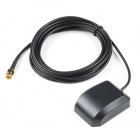
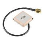
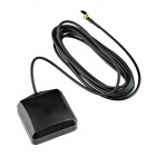
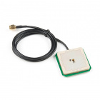
Additional GNSS Antenna Options
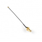
Below are some other GNSS antenna options. Most of these options utilize an SMA connector, so don't forget a U.FL to SMA cable adapter for those antennas.
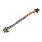
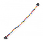
Other Qwiic Cable Accessories
Suggested Reading
If you aren't familiar with the Qwiic system, we recommend reading here for an overview.
| Qwiic Connect System |
We would also recommend taking a look at the following tutorials if you aren't familiar with them.
GPS Basics
Serial Peripheral Interface (SPI)
I2C
How to Work with Jumper Pads and PCB Traces
Getting Started with U-Center for u-blox
Three Quick Tips About Using U.FL
Which GNSS Unit Do I Pick?!
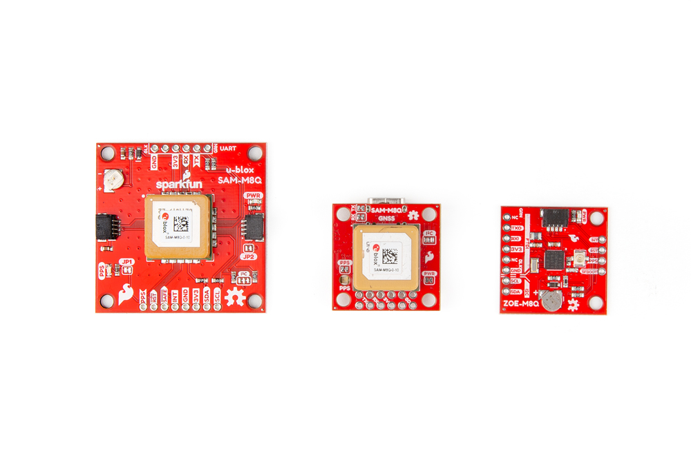
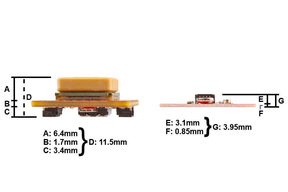
Size and GNSS Antenna
In each of the following Hardware Overview sections we layout the components and connections of each GNSS board. The SAM-M8Q comes in two different variations; a larger board with 1.6" x 1.6" dimensions and a compact version in the 1" x 1" standard Qwiic form-factor. The larger board dimensions provides a increases the ground plane area and performance of the embedded GNSS antenna; meanwhile, the smaller form-factor is more suitable for smaller project enclosures. The ZOE-M8Q also comes in the 1" x 1" standard Qwiic form-factor; however, it does not include an embedded GNSS antenna. Instead a U.FL connector is provided to connect to an external antenna. This offers more flexibility for users to attach their GNSS antenna outside of their project enclosure. The height of the ZOE-M8Q is also smaller than the compact 1" x 1" SAM-M8Q variant.
GNSS Capability Comparison
The SAM-M8Q and ZOE-M8Q GNSS receivers both utilize the 72-channel u-blox M8 engine; therefore, their capabilities are so similar that the differences are negligible. The one major difference between them is that the SAM-M8Q does not connect to the Chinese BeiDou GNSS constellation.
| GPS + GLONASS | GPS | GLONASS | Galileo | BeiDou | ||
|---|---|---|---|---|---|---|
| Horizontal Position Accuracy | 2.5m | 2.5m | 4m | 3m | 3m | |
| Max Navigation Update Rate | 10Hz | 18Hz | 18Hz | 18Hz | 18Hz | |
| Time-To-First-Fix | Cold Start | 26s | 29s | 30s | 45s | 34s |
| Hot Start | 1s | 1s | 1s | 1s | 1s | |
| GPS + GLONASS | GPS | GLONASS | Galileo | |||
|---|---|---|---|---|---|---|
| Horizontal Position Accuracy | 2.5m | 2.5m | 8m | TBD | N/A | |
| Max Navigation Update Rate | 10Hz | 18Hz | 18Hz | 18Hz | N/A | |
| Time-To-First-Fix | Cold Start | 26s | 29s | 30s | TBD | N/A |
| Hot Start | 1s | 1s | 1s | TBD | N/A | |
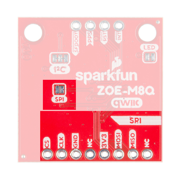
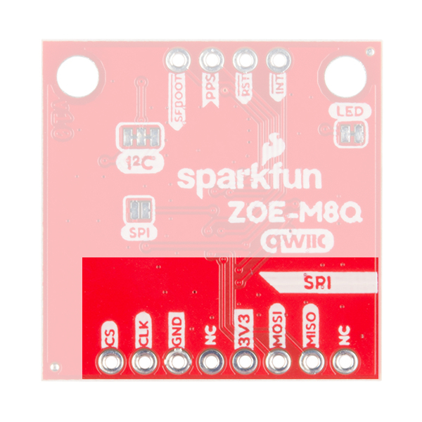
SPI Interface
Both GNSS receivers support I2C and serial communication to receive your NMEA data. However, the ZOE-M8Q also supports a SPI interface. The SPI interface can be enabled by closing the SPI jumper on the bottom of the board.
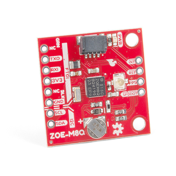
SparkFun ZOE-M8Q Hardware Overview
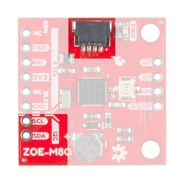
Power
Power for this board should be 3.3V. There is a 3.3V pin on the PTH header along the side of the board, but you can also provide power through the Qwiic connector.
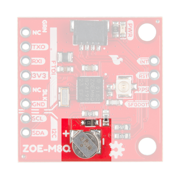
Battery
The small metal disk opposite of the Qwiic connector is a small lithium battery. This battery does not provide power to the IC like the 3.3V system does, but to relevant systems inside the IC that allow for a quick reconnection to satellites. The time to first fix will about ~29 seconds, but after the product has a lock, that battery will allow for a one second time to first fix. This is known as a hot start and lasts for four hours after the board is powered down. The battery provides over a years worth of power to the backup system and charges slowly when the board is powered.
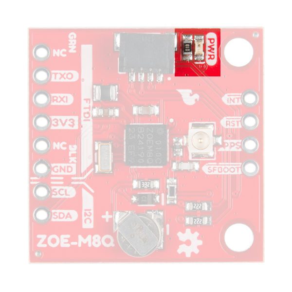
LEDs
There's a single red power LED just above the Qwiic connector to indicate that the board is powered.
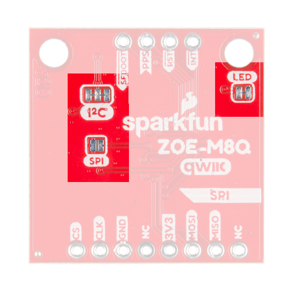
Jumpers
There are three jumpers on the underside of the product, each labeled with its function. The first in the top left of the picture is a three way jumper labeled I²C that connects two pull-up resistors to the I2C data lines. If you have many devices on your I2C data lines, then you may consider cutting these. To the right of that jumper at the very edge of the board is the LED jumper. If you cut this trace it will disconnect the Power LED on the topside of the board. Finally, at the lower left is the SPI jumper that when closed enables SPI communication. The board defaults to I2C and Serial so close that if you'd rather get your NMEA data over SPI.
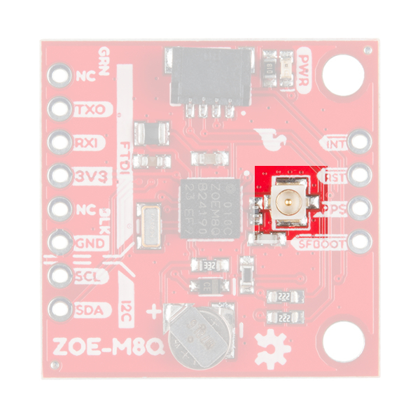
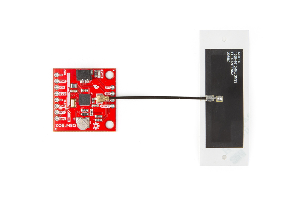
U.FL Connector
The U.FL connector on the board is where you will plug in your antenna. This is a compact connector for RF antennas, that has the same function as the traditional SMA connector. You may be more familiar and even own some antennas that use SMA connectors; never fear, we carry a U.FL to SMA cable adapter. Check out our tutorial on using U.FL connectors, if this be your first.
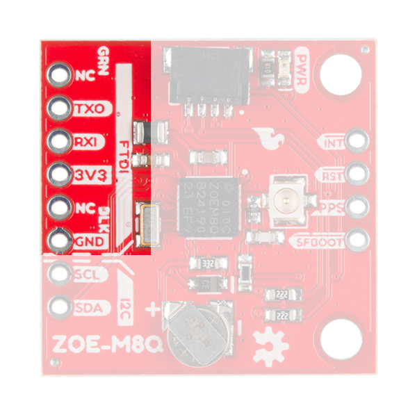
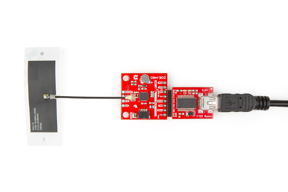
FTDI Header
At the bottom of the board we have the traditional pinout for an FTDI header. Make sure that the FTDI that you use is 3.3V and not 5V! Also, double check that your baud rate is configured to 9600bps.
Qwiic and I2C
Next to the FTDI header at the bottom of the board, there are two pins labeled SDA and SCL which indicates the I2C data lines. Similarly you can just use the Qwiic connector on the left side of the picture. The Qwiic ecosystem is made for fast prototyping by removing the need for soldering. All you need to do is plug a Qwiic cable into the Qwiic connector and voila!
SPI Header
This sets the ZOE-M8Q apart from the SAM-M8Q. On the underside of the product as mentioned above, is a jumper that can be closed to allow for SPI communication. The header is labeled for the pinout for SPI.
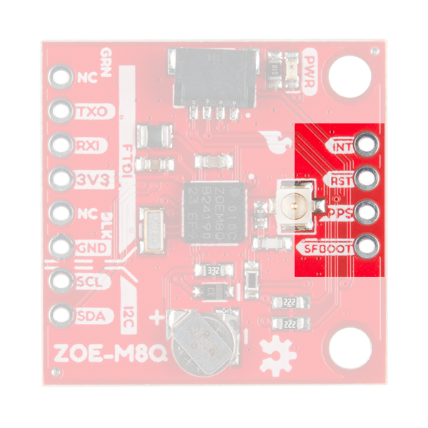
Broken Out Pins
There are four other pins broken out: Pulse per second PPS, Reset RST, Safeboot SAFE, and finally the interrupt pin INT. The first pin PPS outputs pulse trains synchronized with the GNSS or UTC time grid. The signal defaults to once per second but is configurable over a wide range. Read the u-blox Receiver Protocol Specification in the Resources tab for more information. The reset pin resets the chip. The next pin, SAFE is used to start up the IC in safe boot mode. The final pin INT can be used to wake the chip from power save mode.
GNSS Capabilities
The ZOE-M8 is able to connect to up to three different GNSS constellations at a time making it very accurate for its size. Below are the listed capabilities of the GNSS unit.
| GNSS | GPS and GLONASS | GPS | GLONASS | BeiDou | Galileo | ||
|---|---|---|---|---|---|---|---|
| Horizontal Position Accuracy | 2.5m | 2.5m | 4m | 3m | 3m | ||
| Max Navigation Update Rate | ROM | 10Hz | 18Hz | 18Hz | 18Hz | 18Hz | |
| Flash | 5Hz | 10Hz | 10Hz | 10Hz | 10Hz | ||
| Time-To-First-Fix | Cold Start | 26s | 29s | 30s | 34s | 45s | |
| Hot Start | 1s | 1s | 1s | 1s | 1s | ||
| Sensitivity | Tracking and Navigation | -167dBm | -166dBm | -166dBm | -160dBm | -159dBm | |
| Reacquisition | -160dBm | -160dBm | -156dBm | -157dBm | -153dBm | ||
| Cold Start | -148dBm | -148dBm | -145dBm | -143dBm | -138dBm | ||
| Hot Start | -157dBm | -157dBm | -156dBm | -155dBm | -151dBm | ||
| Velocity Accuracy | 0.05m/s | ||||||
| Heading Accuracy | 0.3 degrees |
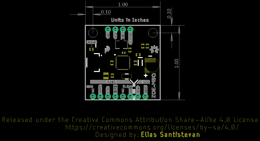
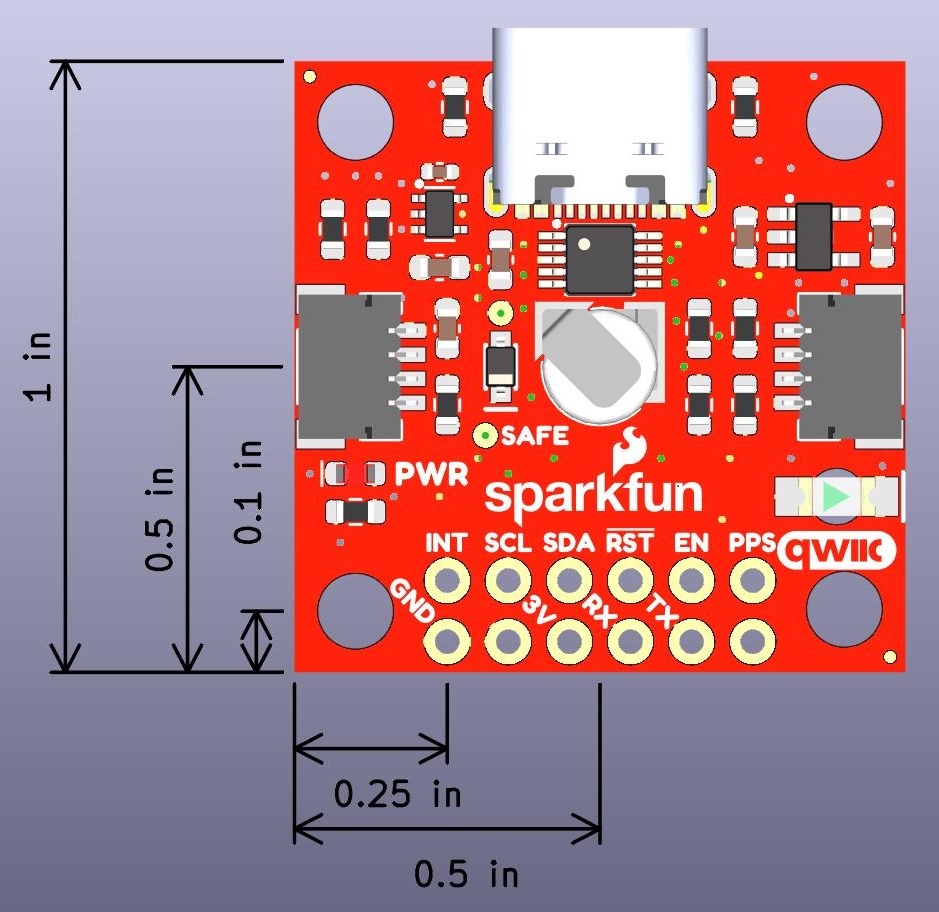
Board Dimensions
The board uses the typical Qwiic board dimension of 1.0"x1.0" . Due to the size of the board and components, there are two mounting holes on the board.
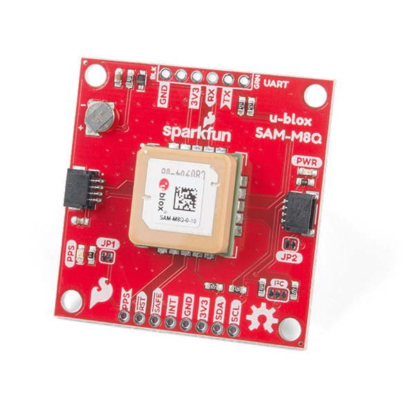
SparkFun SAM-M8Q Hardware Overview
Power
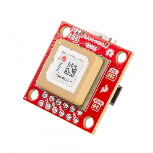
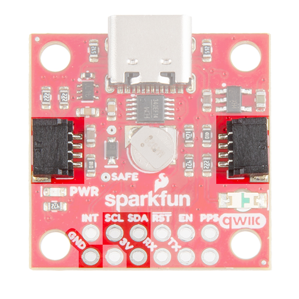
Power for this board is 3.3V. There is a 3.3V pin on the PTH header along the side of the board, but you can also provide power through the Qwiic connector.On the compact variant, power can also be applied through the USB connector.
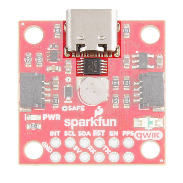
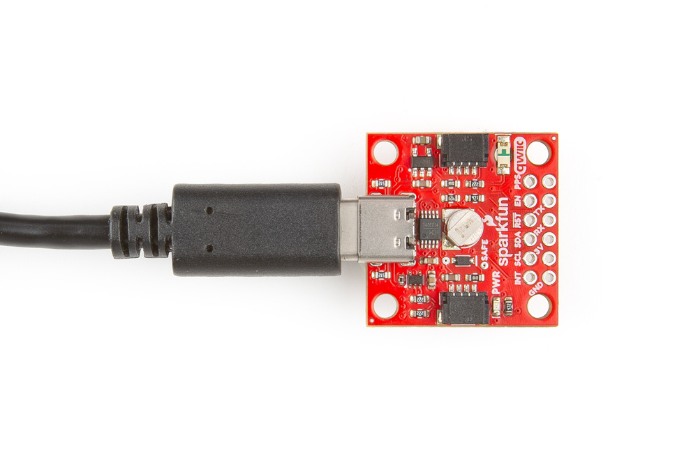
USB
On the compact variant, we provide a CH340 USB-to-serial adapter and USB connector to connect the board directly to a computer. The USB connector can be used to power the board and configure the SAM-M8Q GNSS module without programming a microcontroller. The default baud rate is configured to 9600bps.
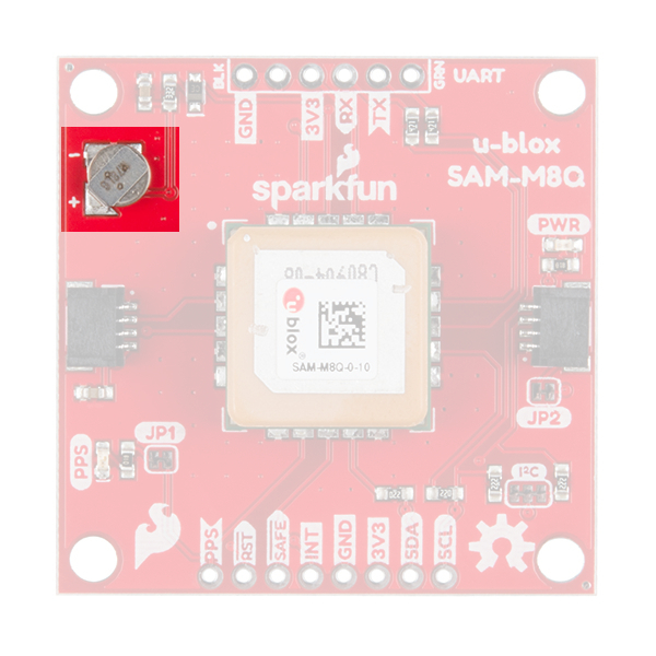
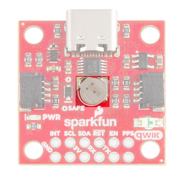
Battery
There is a small metal disk on the board, which is a small lithium battery. This battery does not provide power to the IC bus like the 3.3V system does, but to relevant systems inside the GNSS receiver that allow for a quick reconnection to satellites. The time to first fix will about ~29 seconds, but after it has a lock, that battery will allow for a one second time to first fix. This is known as a hot start and lasts for four hours after the board is powered down. The battery provides over a years worth of power to the backup system and charges slowly when the board is powered.
LEDs
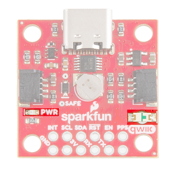
There's a single red power LED just above the Qwiic connector to indicate that the board is powered. There is another LED labeled PPS that is connected to the Pulse Per Second line on the GNSS chip. When connected to a satellite, this line generates a pulse that is synchronized with a GNSS or UTC time grid. By default, you'll see one pulse a second.
Jumpers
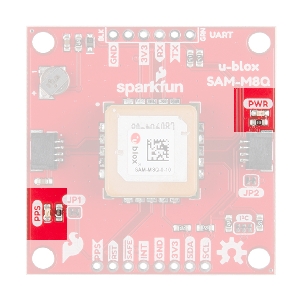
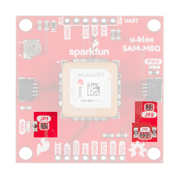
There are three jumpers on the topside of the board, each labeled with its function. At the bottom right of the picture is a three way jumper labeled I²C that connects two 2.2kΩ pull-up resistors to the I2C bus. If you have many devices on your I2C data lines, then you may consider cutting these. Just above that jumper is the JP2 jumper. If you cut this trace it will disconnect the Power LED just above the Qwiic connector. Finally, on the left side of the product is the JP1 jumper that when cut disconnects the PPS LED.
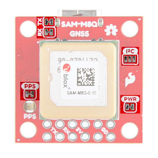
On the compact variant, there are five jumpers on the topside of the board. Similar to larger variant, there are PPS and PWR jumpers to disconnect power from the respective LEDs. Additionally, there is an I2C jumper; however, this jumper can be closed to connect two 2.2kΩ pull-up resistors for the I2C bus. There is also an RX and TX jumpers, which can be cut to disconnect the CH340 USB-to-serial adapter from the serial interface. This disables the USB connection to the GNSS receiver and allows the FTDI PTH header pins to be utilized.
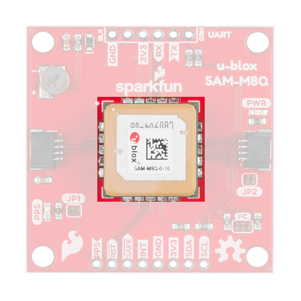
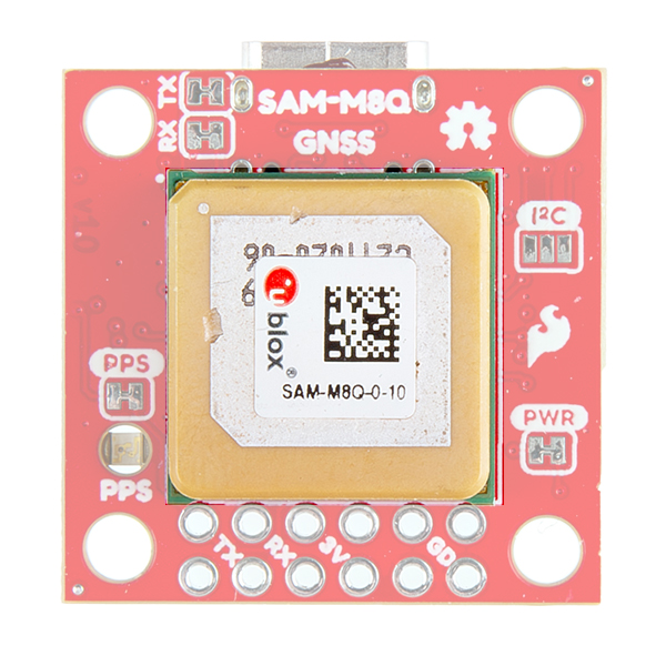
Chip Antenna
This GNSS unit at the center of the PCB may look a bit funky to you. In fact you may be thinking, "Wow, that looks suspiciously like a GNSS Antenna....". That is very astute dear hookup guide peruser. This GNSS IC is actually built into the antenna giving you an all-in-one GNSS solution.
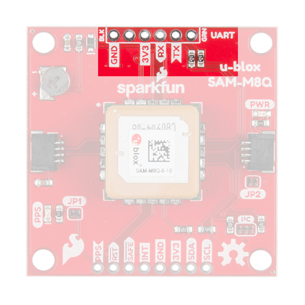
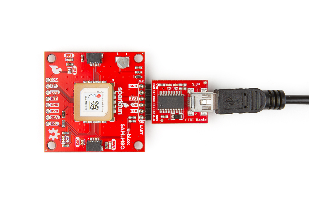
FTDI Header
At the top of the board, we have the traditional pinout for an FTDI header. Make sure that the FTDI that you use is 3.3V and not 5V! Also, double check that your baud rate is configured to 9600bps.
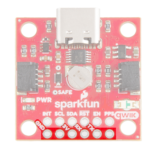
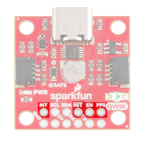
On the compact variant, we have also broken out the same pins at the bottom of the board. However, you do not need an FTDI adapter as we have already provided an CH340 USB-to-serial adapter and USB connector to connect the board directly to a computer. This header should be primarily used to connect a serial device to the the board. In which case, users should cut the RX and TX jumpers to disconnect the CH340 USB-to-serial adapter.
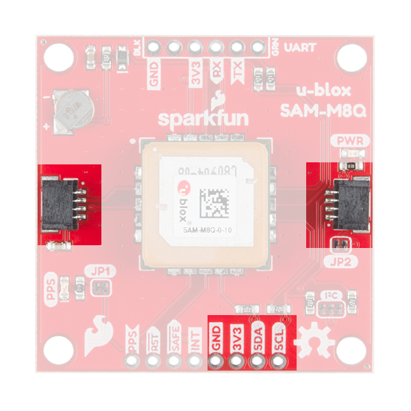
Qwiic and I2C
At the opposite side of the board. There are two pins labeled SDA and SCL which indicates the I2C data lines. Similarly, you can use either of the Qwiic connectors to provide power and utilize I2C. The Qwiic ecosystem is made for fast prototyping by removing the need for soldering. All you need to do is plug a Qwiic cable into the Qwiic connector and voila!
Broken Out Pins
There are four other pins broken out: Pulse per second PPS, Reset RST, Safeboot SAFE, and finally the interrupt pin INT. The first pin PPS outputs pulse trains synchronized with the GNSS or UTC time grid. The signal defaults to once per second but is configurable over a wide range. Read the u-blox Receiver Protocol Specification in the Resources tab for more information. The reset pin resets the chip. The next pin, SAFE is used to start up the IC in safe boot mode. The final pin INT can be used to wake the chip from power save mode.
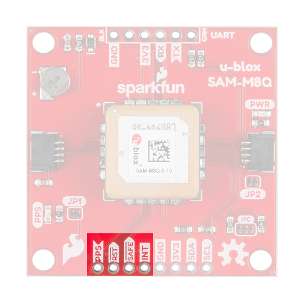
On the compact variant, the SAFEBOOT pin is only exposed as a test point on the board. Instead a EN pin is broken out for the 3.3V regulator on the board. Users can pull this pin low to disable power from the USB connector.
GNSS Capabilities
The SAM-M8 is able to connect to up to three different GNSS constellations at a time making it very accurate for its size. Below are the listed capabilities of the GNSS unit.
| GNSS | GPS and GLONASS | GPS | GLONASS | Galileo | ||
|---|---|---|---|---|---|---|
| Horizontal Position Accuracy | 2.5m | 2.5m | 8m | --- | ||
| Max Navigation Update Rate | ROM | 10Hz | 18Hz | 18Hz | 18Hz | |
| Time-To-First-Fix | Cold Start | 26s | 29s | 30s | --- | |
| Hot Start | 1s | 1s | 1s | --- | ||
| Sensitivity | Tracking and Navigation | -165dBm | -164dBm | -164dBm | -157dBm | |
| Reacquisition | -158dBm | -158dBm | -154dBm | -151dBm | ||
| Cold Start | -146dBm | -146dBm | -143dBm | -136dBm | ||
| Hot Start | -155dBm | -155dBm | -154dBm | -149dBm | ||
| Velocity Accuracy | 0.05m/s | |||||
| Heading Accuracy | 0.3 degrees |
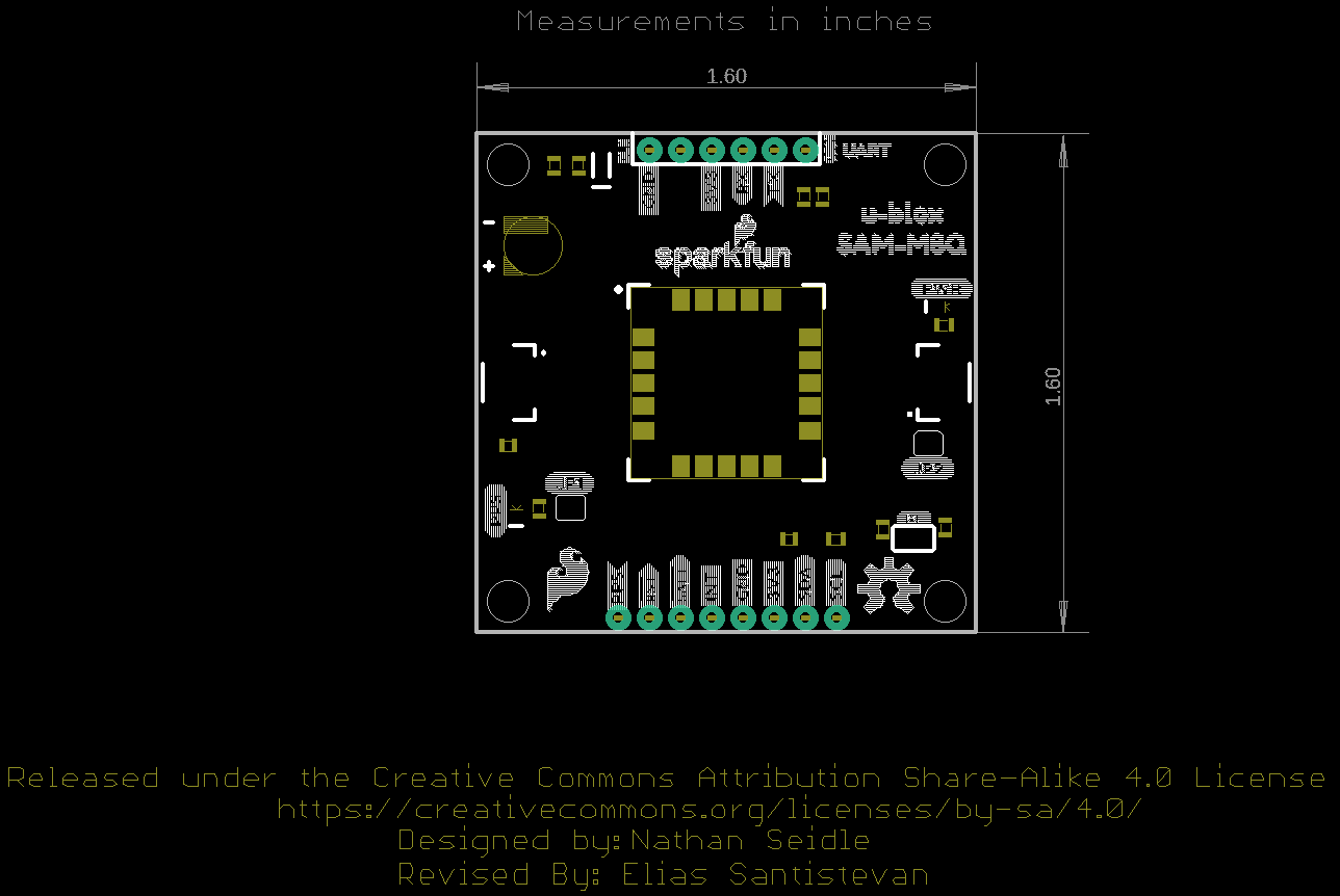
Board Dimensions
The board is 1.6"x1.6", which is slightly bigger than a typical Qwiic board. The board includes four mounting holes on each corner of the board.
Hardware Assembly
U.FL Connector
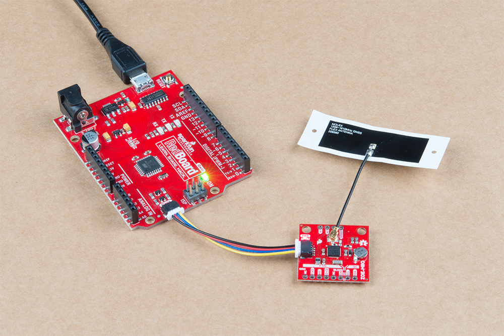
If necessary, attach an external GNSS antenna to the U.FL connector. If you need tips on plugging in the U.FL connector, then check out our U.FL tutorial. Of course, if you're using the SAM-M8Q then you don't need an antenna since it already has one.
Serial Interface
You will need to access the serial interface of the GNSS receiver, to utilize the u-blox u-center software. The compact variant of the SAM-M8Q includes a USB-to-serial adapter and USB connector, which will allow you to connect the board directly to a computer. However for the other boards, you will need to solder male headers to the pass-through-hole (PTH) pins. This will allow you attach a serial-to-USB adapter to the GNSS receiver, to connect the board to a computer. The default baud rate of these modules is configured to 9600bps.
I2C Interface
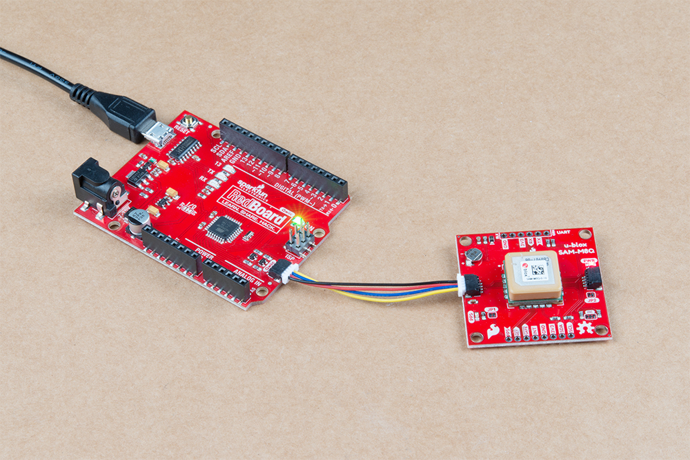
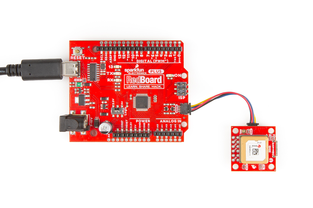
For the example below, I used a Qwiic capable RedBoard and associated USB cable. With that and a Qwiic cable, the assembly is very simple. Plug a Qwiic cable between the RedBoard and the GNSS board.
Software Overview
u-blox u-center Application
u-blox provides its own testing and evaluation software for its GNSS receivers, called u-center. There are two software variants available u-center and u-center 2; make sure to download and install the u-center variant, which is designed for u-blox M8, M9, F9, and legacy GNSS products. (The u-center 2 variant will not be compatible with any of these products.)
Below, are archived links to download the u-center application and user manual. However, to find the latest release please visit the u-center website instead.
SparkFun u-blox Arduino Library
Both the SAM-M8Q and ZOE-M8Q share the same library. These two also share a library with their other u-Blox high-precision cousins. The SparkFun u-Blox Arduino library can be downloaded with the Arduino library manager by searching SparkFun u-blox GNSS; otherwise, you can manually install the library by grabbing the *.zip file from the GitHub repository or by clicking the button below:
There are 13 example sketches provided to get you up and receiving messages from space.
Example Code
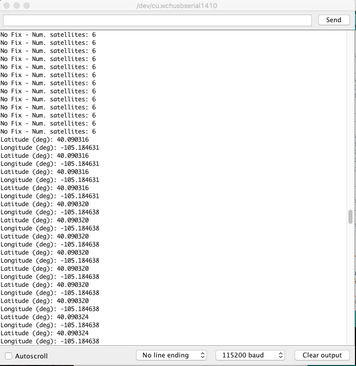
We're just going to look at example two (i.e. "Example2_NMEAParsing.ino" of the Arduino library) which in my opinion, makes it clear the awesomeness of these GNSS receivers. That is to say, talking to satellites and finding out where in the world you are.
language:c
#include <Wire.h> //Needed for I2C to GPS

#include <SparkFun_u-blox_GNSS_Arduino_Library.h> //Click here to get the library:  http://librarymanager/All#SparkFun_u-blox_GNSS
SFE_UBLOX_GNSS myGNSS;

void setup()
{
  Serial.begin(115200);
  Serial.println("SparkFun u-blox Example");

  Wire.begin();

  if (myGNSS.begin() == false)
  {
    Serial.println(F("u-blox GNSS module not detected at default I2C address. Please check wiring. Freezing."));
    while (1);
  }

  //This will pipe all NMEA sentences to the serial port so we can see them
  myGNSS.setNMEAOutputPort(Serial);
}

void loop()
{
  myGNSS.checkUblox(); //See if new data is available. Process bytes as they come in.

  delay(250); //Don't pound too hard on the I2C bus
}
When you upload this code, the GNSS antenna will need a clear view of the sky and you'll have to wait ~29s to get an initial position fix. After the initial position fix, the backup battery on the board will provide power to some internal systems and store the ephemeris data. This will allow for a hot start the next time you turn on the GNSS receiver. The ephemeris data is only valid for about four hours, but it allows you to get a fix within a few seconds. After you get a position fix, the serial terminal will start listing longitude and latitude coordinates, as seen below. Make sure to set the serial monitor to 115200 baud.
Resources and Going Further
Now that you've successfully got your ZOE-M8Q/SAM-M8Q GPS receiver up and running, it's time to incorporate it into your own project!
For more information, check out the resources below:
- SparkFun u-Blox ZOE-M8Q
- SparkFun u-Blox SAM-M8Q
- SparkFun u-Blox SAM-M8Q (Compact)
- SFE Product Showcase
- SparkFun u-blox GNSS Arduino Library
- u-center Software
Are you looking for a GPS receiver with an insane 10mm 3D accuracy? Then check out these other u-Blox based GPS boards by SparkFun below.
Need some inspiration for your next project? Check out some of these related tutorials:
Three Quick Tips About Using U.FL
GNSS Receiver Breakout - MAX-M10S (Qwiic) Hookup Guide
MicroMod GNSS Function Board - NEO-M9N Hookup Guide
MicroMod GNSS Carrier Board (ZED-F9P) Hookup Guide
Or check out this blog post for more ideas: