SparkFun GPS Breakout (ZOE-M8Q and SAM-M8Q) Hookup Guide
 Elias The Sparkiest
SparkFun SAM-M8Q Hardware Overview
Power
Power for this board is 3.3V. There is a 3.3V pin on the PTH header along the side of the board, but you can also provide power through the Qwiic connector.On the compact variant, power can also be applied through the USB connector.
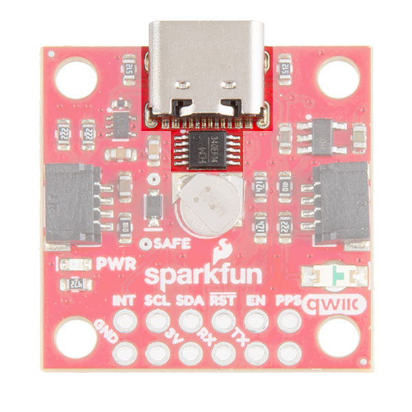
USB
On the compact variant, we provide a CH340 USB-to-serial adapter and USB connector to connect the board directly to a computer. The USB connector can be used to power the board and configure the SAM-M8Q GNSS module without programming a microcontroller. The default baud rate is configured to 9600bps.
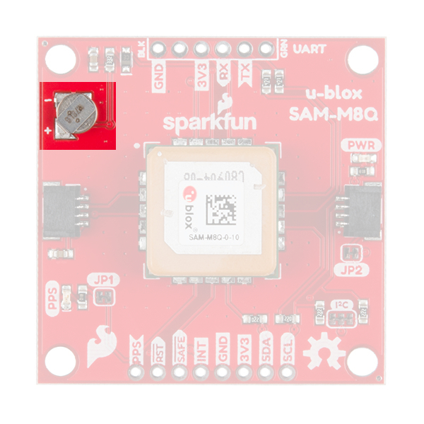
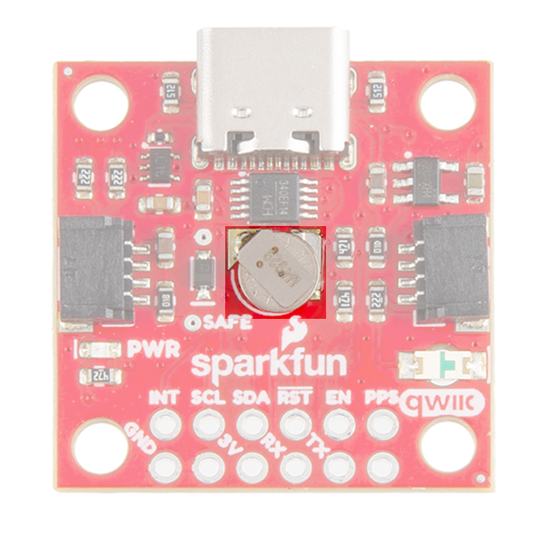
Battery
There is a small metal disk on the board, which is a small lithium battery. This battery does not provide power to the IC bus like the 3.3V system does, but to relevant systems inside the GNSS receiver that allow for a quick reconnection to satellites. The time to first fix will about ~29 seconds, but after it has a lock, that battery will allow for a one second time to first fix. This is known as a hot start and lasts for four hours after the board is powered down. The battery provides over a years worth of power to the backup system and charges slowly when the board is powered.
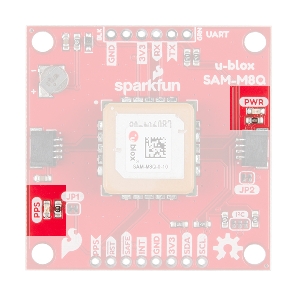
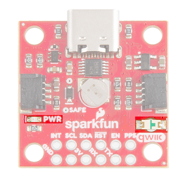
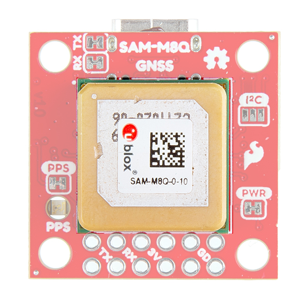
LEDs
There's a single red power LED just above the Qwiic connector to indicate that the board is powered. There is another LED labeled PPS that is connected to the Pulse Per Second line on the GNSS chip. When connected to a satellite, this line generates a pulse that is synchronized with a GNSS or UTC time grid. By default, you'll see one pulse a second.
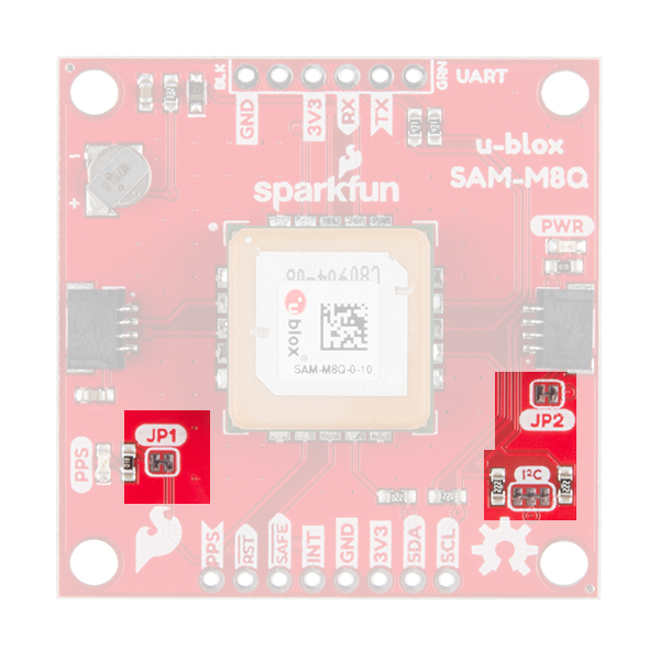
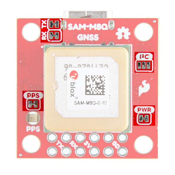
Jumpers
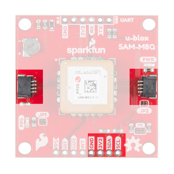
There are three jumpers on the topside of the board, each labeled with its function. At the bottom right of the picture is a three way jumper labeled I²C that connects two 2.2kΩ pull-up resistors to the I2C bus. If you have many devices on your I2C data lines, then you may consider cutting these. Just above that jumper is the JP2 jumper. If you cut this trace it will disconnect the Power LED just above the Qwiic connector. Finally, on the left side of the product is the JP1 jumper that when cut disconnects the PPS LED.
On the compact variant, there are five jumpers on the topside of the board. Similar to larger variant, there are PPS and PWR jumpers to disconnect power from the respective LEDs. Additionally, there is an I2C jumper; however, this jumper can be closed to connect two 2.2kΩ pull-up resistors for the I2C bus. There is also an RX and TX jumpers, which can be cut to disconnect the CH340 USB-to-serial adapter from the serial interface. This disables the USB connection to the GNSS receiver and allows the FTDI PTH header pins to be utilized.
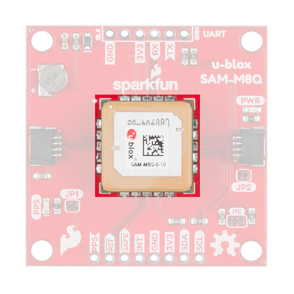
Chip Antenna
This GNSS unit at the center of the PCB may look a bit funky to you. In fact you may be thinking, "Wow, that looks suspiciously like a GNSS Antenna....". That is very astute dear hookup guide peruser. This GNSS IC is actually built into the antenna giving you an all-in-one GNSS solution.
FTDI Header
At the top of the board, we have the traditional pinout for an FTDI header. Make sure that the FTDI that you use is 3.3V and not 5V! Also, double check that your baud rate is configured to 9600bps.
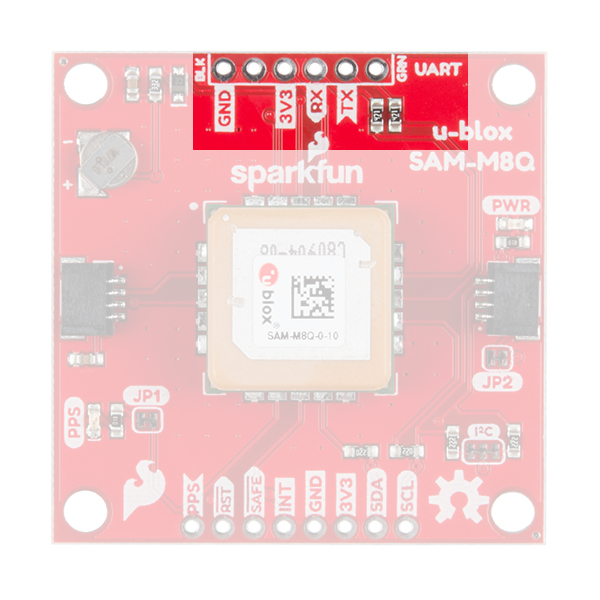
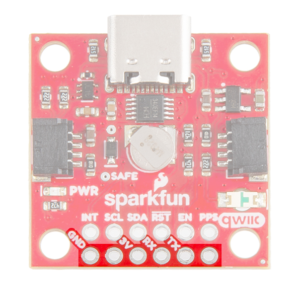
On the compact variant, we have also broken out the same pins at the bottom of the board. However, you do not need an FTDI adapter as we have already provided an CH340 USB-to-serial adapter and USB connector to connect the board directly to a computer. This header should be primarily used to connect a serial device to the the board. In which case, users should cut the RX and TX jumpers to disconnect the CH340 USB-to-serial adapter.
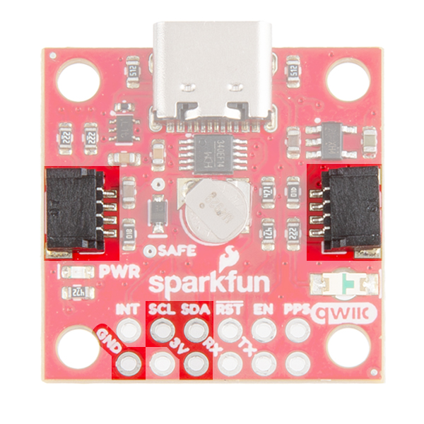
Qwiic and I2C
At the opposite side of the board. There are two pins labeled SDA and SCL which indicates the I2C data lines. Similarly, you can use either of the Qwiic connectors to provide power and utilize I2C. The Qwiic ecosystem is made for fast prototyping by removing the need for soldering. All you need to do is plug a Qwiic cable into the Qwiic connector and voila!
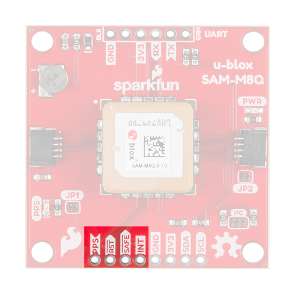
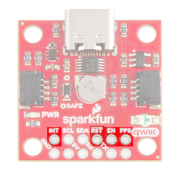
Broken Out Pins
There are four other pins broken out: Pulse per second PPS, Reset RST, Safeboot SAFE, and finally the interrupt pin INT. The first pin PPS outputs pulse trains synchronized with the GNSS or UTC time grid. The signal defaults to once per second but is configurable over a wide range. Read the u-blox Receiver Protocol Specification in the Resources tab for more information. The reset pin resets the chip. The next pin, SAFE is used to start up the IC in safe boot mode. The final pin INT can be used to wake the chip from power save mode.
On the compact variant, the SAFEBOOT pin is only exposed as a test point on the board. Instead a EN pin is broken out for the 3.3V regulator on the board. Users can pull this pin low to disable power from the USB connector.
GNSS Capabilities
The SAM-M8 is able to connect to up to three different GNSS constellations at a time making it very accurate for its size. Below are the listed capabilities of the GNSS unit.
| GNSS | GPS and GLONASS | GPS | GLONASS | Galileo | ||
|---|---|---|---|---|---|---|
| Horizontal Position Accuracy | 2.5m | 2.5m | 8m | --- | ||
| Max Navigation Update Rate | ROM | 10Hz | 18Hz | 18Hz | 18Hz | |
| Time-To-First-Fix | Cold Start | 26s | 29s | 30s | --- | |
| Hot Start | 1s | 1s | 1s | --- | ||
| Sensitivity | Tracking and Navigation | -165dBm | -164dBm | -164dBm | -157dBm | |
| Reacquisition | -158dBm | -158dBm | -154dBm | -151dBm | ||
| Cold Start | -146dBm | -146dBm | -143dBm | -136dBm | ||
| Hot Start | -155dBm | -155dBm | -154dBm | -149dBm | ||
| Velocity Accuracy | 0.05m/s | |||||
| Heading Accuracy | 0.3 degrees |
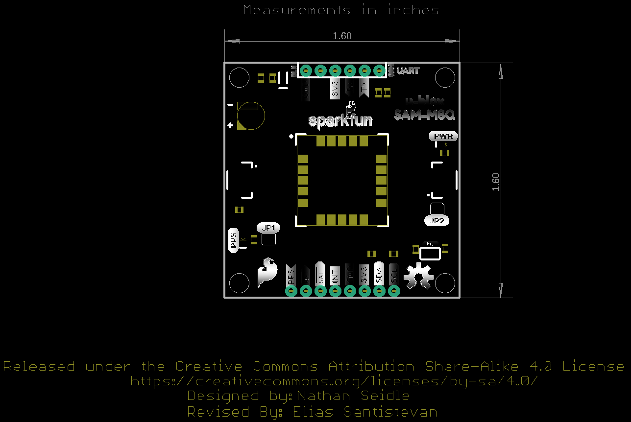
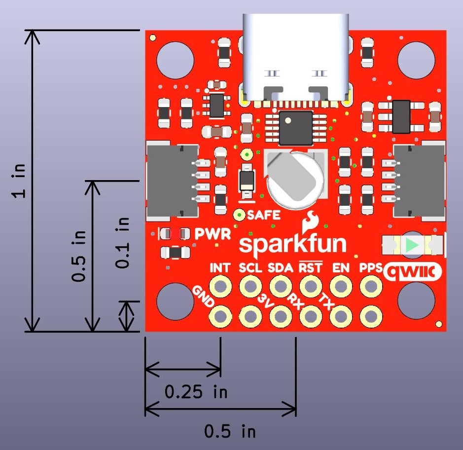
Board Dimensions
The board is 1.6"x1.6", which is slightly bigger than a typical Qwiic board. The board includes four mounting holes on each corner of the board.