SparkFun Blocks for Intel® Edison - 9 Degrees of Freedom Block
 Shawn Hymel,
  CaseyTheRobot,
  SFUptownMaker
Introduction
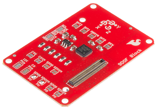
The 9 Degrees of Freedom Block for the Intel® Edison uses the LSM9DS0 9DOF IMU for full-range motion sensing. Use this Block to determine orientation, acceleration, and compass headings. The LSM9DS0 combines a 3-axis accelerometer, a 3-axis gyroscope, and a 3-axis magnetometer. The IMU is connected to the Edison through the I2C bus.
Suggested Reading
If you are unfamiliar with Blocks, take a look at the General Guide to Sparkfun Blocks for Intel Edison.
Other tutorials that may help you on your Edison adventure include:
Board Overview
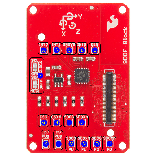
The 9DOF Block has a lot of jumpers on it, but you can use it without understanding or changing any of them. Here's a description of each one:
A (INT2) - Accelerometer/magnetometer interrupt 2. This pin can be configured to change on a number of different conditions. See datasheet pp 58 and 65-67 for more details on configuring the device. Closing this jumper with a solder blob connects the INT2 pin on the LSM9DS0 to GPIO 49 on the Edison.
B (INT1) - Accelerometer/magnetometer interrupt 1. This pin can be configured to change on a number of different conditions. See datasheet pp 58 and 63-65 for more details on configuring the device. Closing this jumper with a solder blob connects the INT2 pin on the LSM9DS0 to GPIO 48 on the Edison.
C (DRDYG) - Data Ready, gyroscope. Closing this jumper connects the pin to GPIO 47. See datasheet page 43 for information on configuring this pin.
D (INTG) - Gyroscope interrupt. This pin can be configured to change on a number of different conditions. Closing this jumper will connect the pin to GPIO 46. See datasheet pages 43 and 47-50 for information on configuring this pin.
E (DEN) - Data enable, gyroscope. Enable or !pause data collection. This pin can safely be ignored. Closing this jumper allows processor control of data collection via GPIO 165.
F (CLOCK/DATA) - I/O interface selection jumpers. Default setting is to I2C1 but cutting the small trace visible between the two upper pads of each jumper and closing the bottom two pads with a solder blob allow the user to route control to SPIDEV2. SPI is currently an unsupported feature and will likely be removed from a future revision.
G (CSG) - SPI chip select, gyroscope. Closing this jumper connects the signal to GPIO 111 on the Edison, which is FS0 on SPIDEV2. The CS pin can be either handled manually or by the driver. SPI is currently an unsupported feature and will likely be removed from a future revision.
H (CSXM) - SPI chip select, accelerometer/magnetometer. Closing this jumper connects the signal to GPIO 110 on the Edison, which is FS1 on SPIDEV2. The CS pin can be either handled manually or by the driver. SPI is currently an unsupported feature and will likely be removed from a future revision.
I (SDOG) - SPI serial data out (MISO), gyroscope. SPI is currently an unsupported feature and will likely be removed from a future revision.
J (SDOXM) - Serial data out (MISO), accelerometer/magnetometer. SPI is currently an unsupported feature and will likely be removed from a future revision.
K (I2C PUs) - Pull-up resistor removal for I2C SDA and SCL lines. Most likely, you won't want to remove these resistors from the system; however, if you have a lot of devices on the I2C bus, you may need to remove some of the pull-ups from the lines to reduce the pull-up strength. (No solder indicates that pull-ups are disabled. Connect all three pads with a solder blob to enable pull-ups.)
L (CS PUs) - Pull-up resistor removal for SPI chip select lines. Normally pull-up resistors should be left in place. SPI is currently an unsupported feature and will likely be removed from a future revision.
M (SDOG PU) - Closed by default, this pin sets the I2C address used by the gyroscope. When closed, the gyroscope's address is 0x6b. When open, jumper SDOG PD (labeled 'O' above) must be closed.
N (SDOXM PU) - Closed by default, this pin sets the I2C address used by the magnetometer/accelerometer. When closed, their collective address is 0x1d. When open, jumper SDOXM PD (labeled 'P' above) must be closed.
O (SDOG PD) - Open by default, this pin sets the I2C address used by the gyroscope. When closed, the gyroscope's address is 0x6a.
P (SDOXM PD) - Open by default, this pin sets the I2C address used by the magnetometer/accelerometer. When closed, their collective address is 0x1e.
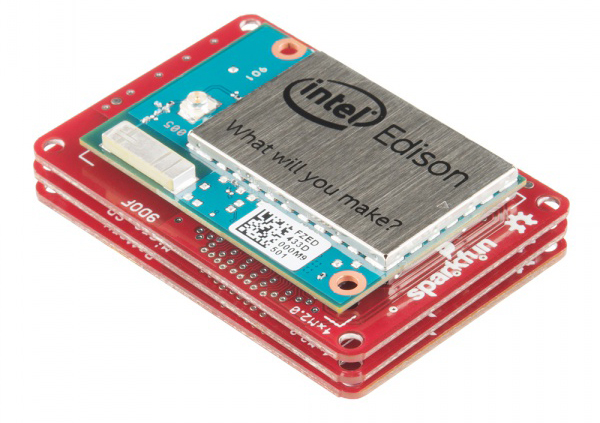
Connecting the 9 DOF Block
To use the 9 DOF Block simply attach an Intel Edison to the back of the board or add it to your current stack. Blocks can be stacked without hardware but it leaves the expansion connectors unprotected from mechanical stress.
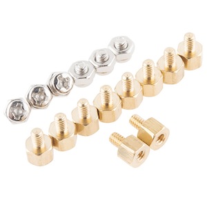
We have a nice Hardware Pack available that gives enough hardware to secure three blocks and an Edison.
NOTE: The 9 DOF Block does not have console access or a voltage regulator. It is recommended to use a console communication block in conjunction with this block like ones found in the General Guide to Sparkfun Blocks for Intel Edison.
C++ Code Examples
We're assuming that you're using the Eclipse IDE as detailed in our Beyond Arduino tutorial. If you aren't, you'll need to read over that tutorial to get up to speed.
Getting Started
Follow the instructions in the programming tutorial to create a new project named "SparkFun_9DOF_Edison_Block_Example". Once you've created the project, open the project files on disk (hint: you can find the path to the project by choosing "Properites" from the project menu), and copy the three source files found in the Edison 9DOF Block CPP library GitHub repository into the "src" directory.
Code
Everything you need to know is in the comments.
language:c
#include "mraa.hpp"
#include <iostream>
#include <unistd.h>
#include "SFE_LSM9DS0.h"
using namespace std;

int main()
{
  LSM9DS0 *imu;
  imu = new LSM9DS0(0x6B, 0x1D);
  // The begin() function sets up some basic parameters and turns the device
  //  on; you may not need to do more than call it. It also returns the "whoami"
  //  registers from the chip. If all is good, the return value here should be
  //  0x49d4. Here are the initial settings from this function:
  //  Gyro scale:        245 deg/sec max
  //  Xl scale:          4g max
  //  Mag scale:         2 Gauss max
  //  Gyro sample rate:  95Hz
  //  Xl sample rate:    100Hz
  //  Mag sample rate:   100Hz
  // These can be changed either by calling appropriate functions or by
  //  pasing parameters to the begin() function. There are named constants in
  //  the .h file for all scales and data rates; I won't reproduce them here.
  //  Here's the list of fuctions to set the rates/scale:
  //  setMagScale(mag_scale mScl)      setMagODR(mag_odr mRate)
  //  setGyroScale(gyro_scale gScl)    setGyroODR(gyro_odr gRate)
  //  setAccelScale(accel_scale aScl)  setGyroODR(accel_odr aRate)
  // If you want to make these changes at the point of calling begin, here's
  //  the prototype for that function showing the order to pass things:
  //  begin(gyro_scale gScl, accel_scale aScl, mag_scale mScl,
  //                gyro_odr gODR, accel_odr aODR, mag_odr mODR)
  uint16_t imuResult = imu->begin();
  cout<<hex<<"Chip ID: 0x"<<imuResult<<dec<<" (should be 0x49d4)"<<endl;

  bool newAccelData = false;
  bool newMagData = false;
  bool newGyroData = false;
  bool overflow = false;

  // Loop and report data
  while (1)
  {
    // First, let's make sure we're collecting up-to-date information. The
    //  sensors are sampling at 100Hz (for the accelerometer, magnetometer, and
    //  temp) and 95Hz (for the gyro), and we could easily do a bunch of
    //  crap within that ~10ms sampling period.
    while ((newGyroData & newAccelData & newMagData) != true)
    {
      if (newAccelData != true)
      {
        newAccelData = imu->newXData();
      }
      if (newGyroData != true)
      {
        newGyroData = imu->newGData();
      }
      if (newMagData != true)
      {
        newMagData = imu->newMData(); // Temp data is collected at the same
                                      //  rate as magnetometer data.
      }
    }

    newAccelData = false;
    newMagData = false;
    newGyroData = false;

    // Of course, we may care if an overflow occurred; we can check that
    //  easily enough from an internal register on the part. There are functions
    //  to check for overflow per device.
    overflow = imu->xDataOverflow() |
               imu->gDataOverflow() |
               imu->mDataOverflow();

    if (overflow)
    {
      cout<<"WARNING: DATA OVERFLOW!!!"<<endl;
    }

    // Calling these functions causes the data to be read from the IMU into
    //  10 16-bit signed integer public variables, as seen below. There is no
    //  automated check on whether the data is new; you need to do that
    //  manually as above. Also, there's no check on overflow, so you may miss
    //  a sample and not know it.
    imu->readAccel();
    imu->readMag();
    imu->readGyro();
    imu->readTemp();

    // Print the unscaled 16-bit signed values.
    cout<<"-------------------------------------"<<endl;
    cout<<"Gyro x: "<<imu->gx<<endl;
    cout<<"Gyro y: "<<imu->gy<<endl;
    cout<<"Gyro z: "<<imu->gz<<endl;
    cout<<"Accel x: "<<imu->ax<<endl;
    cout<<"Accel y: "<<imu->ay<<endl;
    cout<<"Accel z: "<<imu->az<<endl;
    cout<<"Mag x: "<<imu->mx<<endl;
    cout<<"Mag y: "<<imu->my<<endl;
    cout<<"Mag z: "<<imu->mz<<endl;
    cout<<"Temp: "<<imu->temperature<<endl;
    cout<<"-------------------------------------"<<endl;

    // Print the "real" values in more human comprehensible units.
    cout<<"-------------------------------------"<<endl;
    cout<<"Gyro x: "<<imu->calcGyro(imu->gx)<<" deg/s"<<endl;
    cout<<"Gyro y: "<<imu->calcGyro(imu->gy)<<" deg/s"<<endl;
    cout<<"Gyro z: "<<imu->calcGyro(imu->gz)<<" deg/s"<<endl;
    cout<<"Accel x: "<<imu->calcAccel(imu->ax)<<" g"<<endl;
    cout<<"Accel y: "<<imu->calcAccel(imu->ay)<<" g"<<endl;
    cout<<"Accel z: "<<imu->calcAccel(imu->az)<<" g"<<endl;
    cout<<"Mag x: "<<imu->calcMag(imu->mx)<<" Gauss"<<endl;
    cout<<"Mag y: "<<imu->calcMag(imu->my)<<" Gauss"<<endl;
    cout<<"Mag z: "<<imu->calcMag(imu->mz)<<" Gauss"<<endl;
    // Temp conversion is left as an example to the reader, as it requires a
    //  good deal of device- and system-specific calibration. The on-board
    //  temp sensor is probably best not used if local temp data is required!
    cout<<"-------------------------------------"<<endl;
    sleep(1);
  }

  return MRAA_SUCCESS;
}
Resources and Going Further
Now that you have had a brief overview of the 9 DOF Block, take a look at some of these other tutorials. These tutorials cover programming, Block stacking, and interfacing with the Intel Edison ecosystems.
Edison General Topics:
- General Guide to Sparkfun Blocks for Intel Edison
- Edison Getting Started Guide
- Loading Debian (Ubilinix) on the Edison
Block Specific Topics:
Check out these other Edison related tutorials from SparkFun: