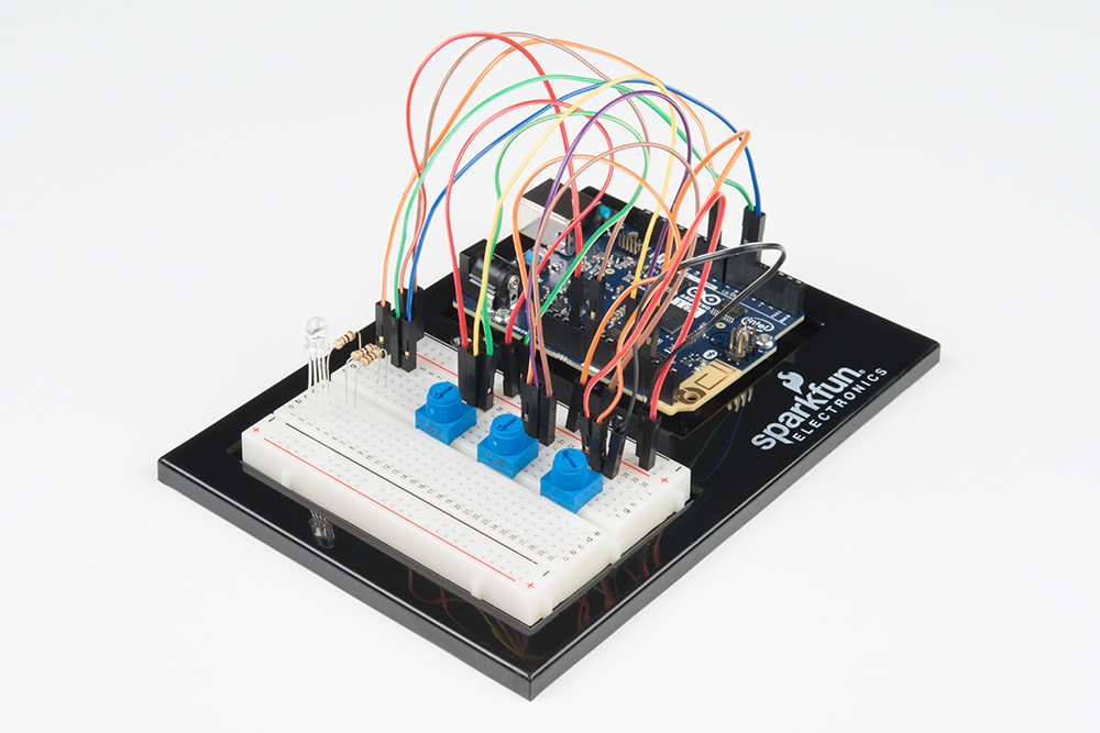
This SparkFun Inventor's Kit Experiment Guide is your map for navigating the waters of beginning embedded electronics using the Intel® Curie-based Arduino 101® or Genuino 101® board. This guide contains all the information you will need to explore the 21 circuits of the SparkFun Inventor's Kit for the Arduino 101. At the center of this guide is one core philosophy -- that anyone can (and should) play around with cutting-edge electronics.
When you're done with this guide, you'll have the know-how to start creating your own projects and experiments, from building robots and game controllers to IoT (Internet of Things) and data logging, the world will be your oyster. Now enough talking -- let's start inventing!
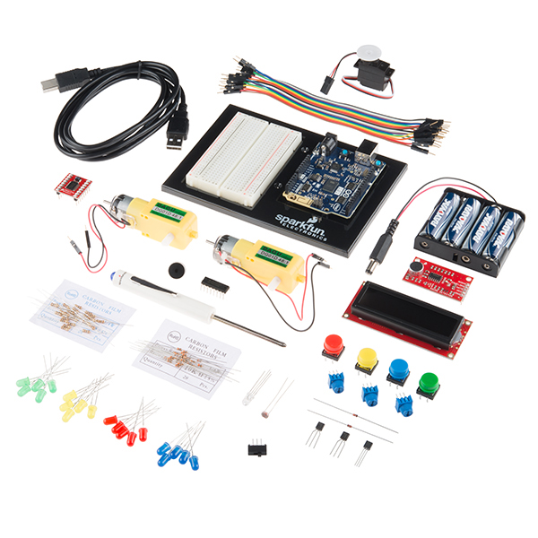
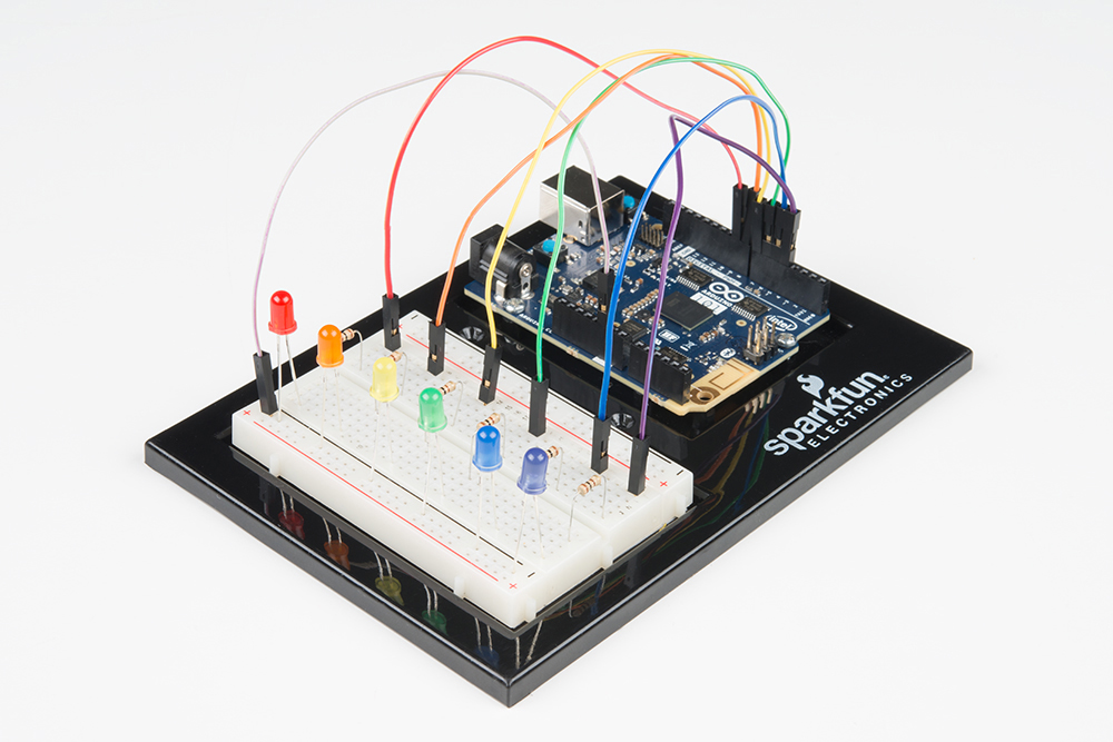
Here are all of the parts in the SparkFun Inventor's Kit for the Arduino 101/Genuino 101 Board (101 SIK):
The following is a list of the experiements you will complteye using this 101 SIK Experiment Guide. Alternatively, you can navigate around using the buttons on the right.
Before continuing with this guide, we recommend you be somewhat familiar with the concepts in the following tutorials:
At SparkFun, our engineers and educators have been improving this kit and coming up with new experiments for a long time. We would like to give attribution to Oomlout, since we originally started working off the Arduino Kit material many years ago. Both the Oomlout and SparkFun versions are licensed under the Creative Commons Attribution Share-Alike 3.0 Unported License.
To view a copy of this license visit this link, or write: Creative Commons, 171 Second Street, Suite 300, San Francisco, CA 94105, USA.

The Arduino 101 is a learning and development board that delivers the performance and low-power consumption of the Intel Curie module with the simplicity of Arduino at an entry-level price. This development board keeps the same robust form factor and peripheral list of the UNO with the addition of on-board Bluetooth Low Energy capabilities and a 6-axis accelerometer and gyroscope called an Inertial Measurement Unit (IMU) to help you easily expand your creativity into the connected world.
The Intel Curie module contains two tiny cores, an x86 (Quark) and a 32-bit ARC architecture core, both clocked at 32MHz. The Intel tool chain compiles your Arduino sketches optimally across both cores to accomplish the most demanding tasks. The Arduino 101 board comes with 14 digital input/output pins (of which four can be used as PWM outputs), six analog inputs, a USB connector for serial communication and sketch upload, a power jack, an ICSP header with SPI signals and I2C dedicated pins. The board operating voltage and I/O is 3.3V, but all pins are protected against 5V overvoltage.
In order to get your 101 up and running, you'll need to download the newest version of the Arduino software first from www.arduino.cc (it's free and open source!). This software, known as the Arduino IDE, will allow you to program the board to do exactly what you want. It’s like a word processor for writing programs. With an internet-capable computer, open up your favorite browser, and go to Arduino download page.
Check out our Installing Arduino IDE tutorial to see in detail how to install the Arduino IDE on your computer.
Since the advent of Arduino version 1.6.2, Arduino has made it much easier to add and update what boards you can program with the Arduino IDE. This has been made possible by the Boards Manager. The Arduino 101 is not part of the standard core set of boards that come with the original download of the Arduino IDE, so you will have to add it through the Boards Manager.
To access the Boards Manager, open the Arduino IDE. From the dropdown menu at the top select Tools > Board > Boards Manager.... This will bring up the Boards Manager as shown below.
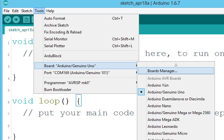

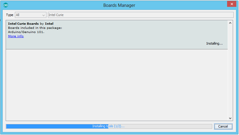
In the Boards Manager search for "Intel Curie." This should bring up one option, which, at this time, is the 101. Select this option and click "Install." Depending on the speed of your network connection, this may take a few minutes. This process is downloading the drivers your computer will need for the board as well as the example code, libraries and board definitions. A number of dialogue boxes will pop up asking you for permission to install drivers and make changes to certain files; go ahead and accept those.
Once this process is complete, we recommend fully closing your Arduino IDE and reopening it. Once it is open and ready, you can plug your 101 into your computer using a USB cable.
Use the USB cable provided in the SparkFun Inventor's Kit (SIK) to connect the 101 board to one of your computer’s USB inputs.
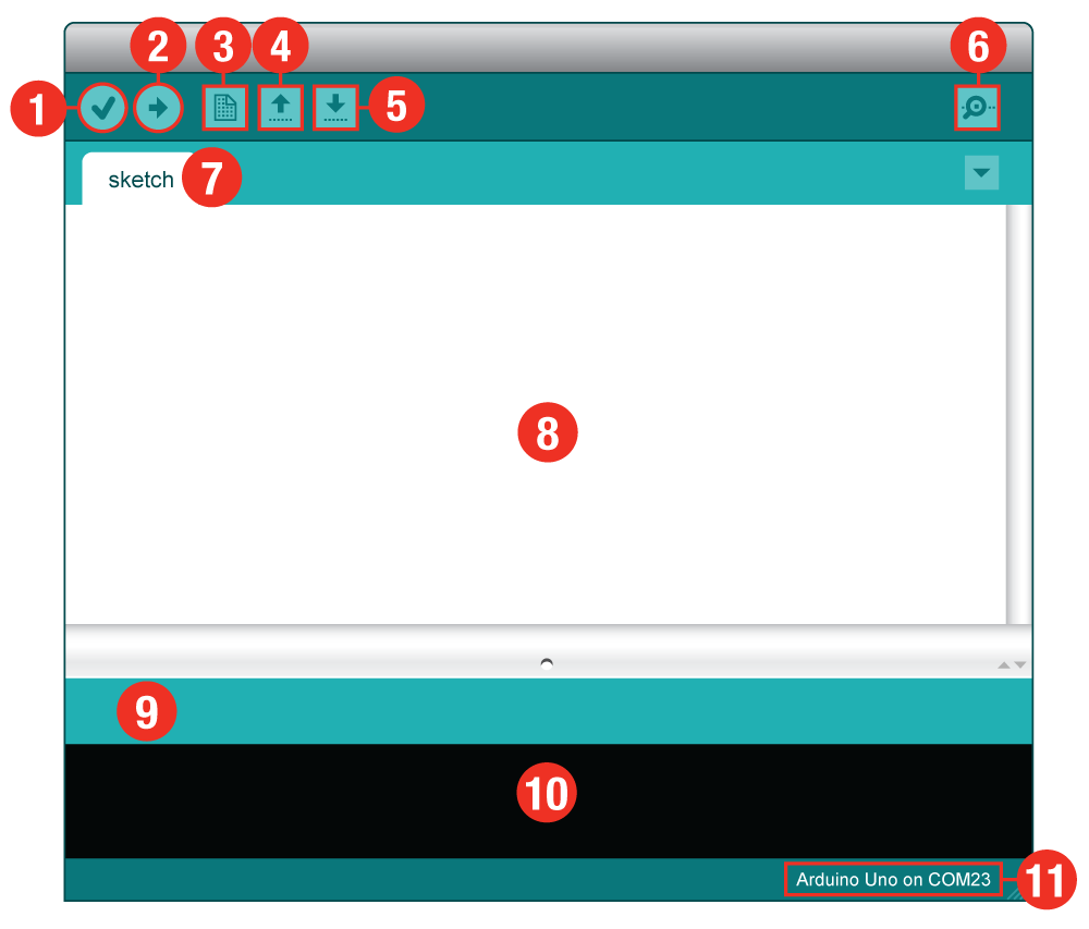
Now, it's finally time to open up the Arduino software. You'll be presented with a window that looks something like this:
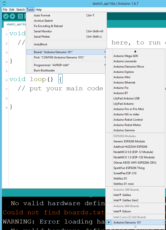
Before we can start jumping into the experiments, there are a few adjustments we need to make. This step is required to tell the Arduino IDE which of the many Arduino boards we have. Go up to the Tools menu. Then hover over Board and make sure Arduino/Genuino 101 is selected.
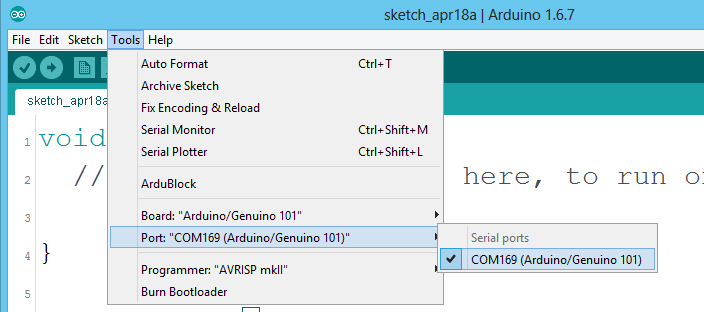
Next up we need to tell the Arduino IDE to which of our computer's serial ports the 101 is connected. Again,, go up to Tools, hover over Port, and select your 101's serial port. This will have Arduino 101 next to the port number in parentheses.
Window Users: This is likely to be COM3 or higher (COM1 and COM2 are usually reserved for hardware serial ports). If there are multiple COM ports available, the 101 is likely the highest numbered port in the list. To be certain, you can also disconnect your 101 and reopen the menu; the entry that disappears should be the 101. Reconnect the board and select that serial port.
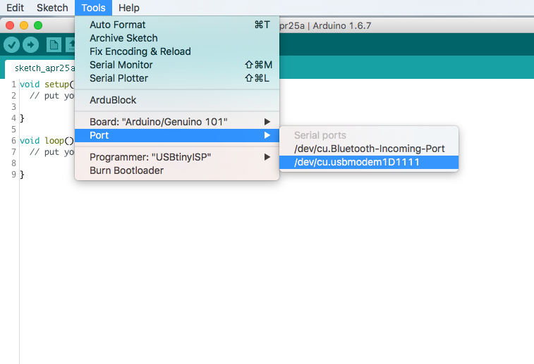
Mac Users: Select the serial device of the 101 from the Tools, then hover over Port. On the Mac, this should be something with /dev/tty.usbmodem or /dev/tty.usbserial in it.
Linux Users: Please visit the Arduino Learning Linux section to learn more about Arduino on Linux.
You are so close to to being done with setup! Download the SIK Guide Code. Click the following link to download the code:
Window Users: Unzip the file “101_SIK_Guide_Code.” It should be located in your browser’s “Downloads” folder. Right click the zipped folder and choose “unzip.” Copy the “SIK Guide Code” folder into Arduino’s folder named “examples.”
Mac Users: Unzip the file “101_SIK_Guide_Code.” It should be located in your browser’s “Downloads” folder. Right click the zipped folder and unzip. Find “Arduino” in your applications folder. Right click (ctrl + click) on “Arduino.” Select “Show Package Contents.” Then, click through folders Contents > Resources > Java > Examples. Copy the “101 SIK Guide Code” folder into Arduino’s folder named “examples.”
LEDs are small, powerful lights that are used in many different applications. To start off, we will work on blinking an LED, the Hello World of microcontrollers. That's right -- it's as simple as turning a light on and off. It might not seem like much, but establishing this important baseline will give you a solid foundation as we work toward more complex experiments.
You will need the following parts:
If you are conducting this experiment and didn't get the 101 SIK, we suggest using these parts:

You will also need either an Arduino 101 OR Genuino 101 board.


Before continuing with this experiment, we recommend you be familiar with the concepts in the following tutorial:
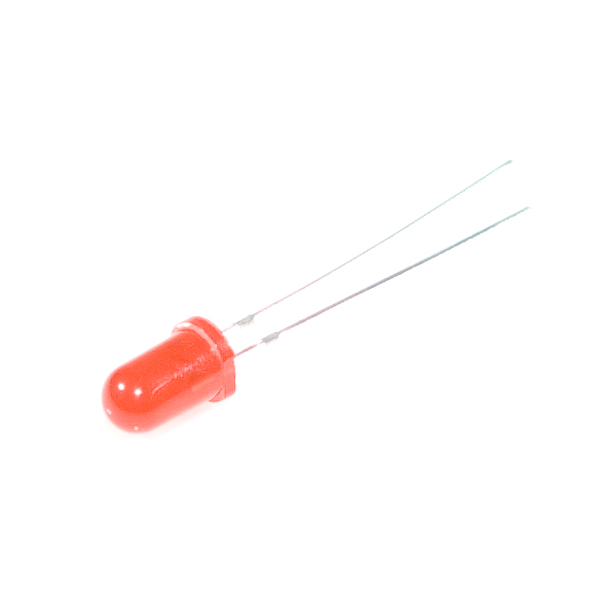
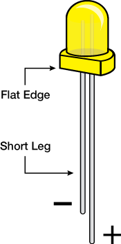
A Light-Emitting Diode (LED) will only let current through it in one direction. Think of an LED as a one-way street. When current flows through the LED, it lights up! When you are looking at the LED, you will notice that its legs are different lengths. The long leg, the "anode," is where current enters the LED. This pin should always be connected to the current source. The shorter leg, the "cathode," is the current’s exit. The short leg should always be connected to a pathway to ground.
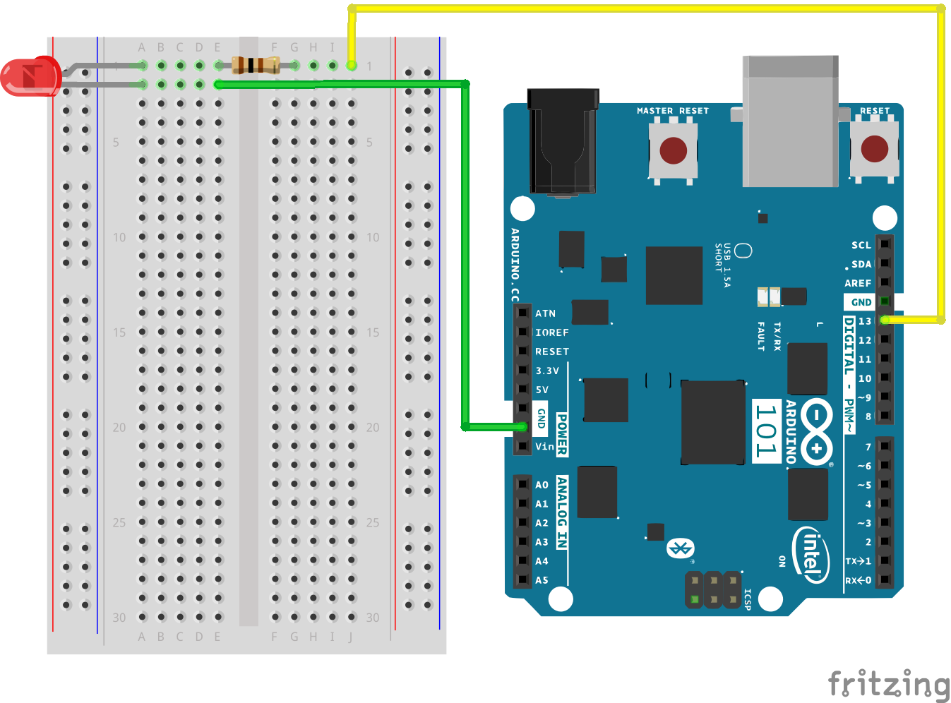
LEDs are finicky when it comes to how much current you apply to them. Too much current can lead to a burnt-out LED. To restrict the amount of current that passes through the LED, we use a resistor in line with the power source and the LED's long leg; this is called a current-limiting resistor. With the 101 board, you should use a 100 Ohm resistor. We have included a baggy of them in the kit just for this reason!
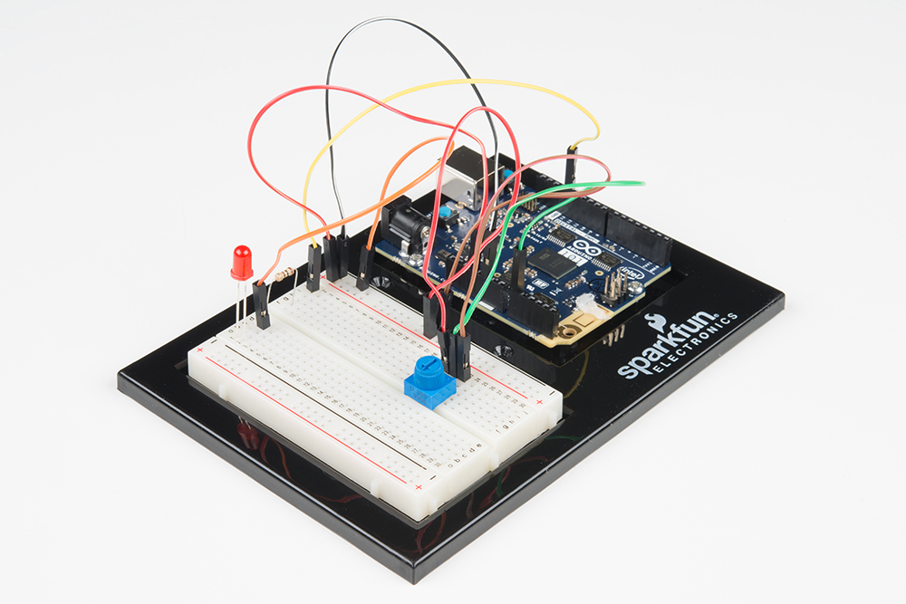
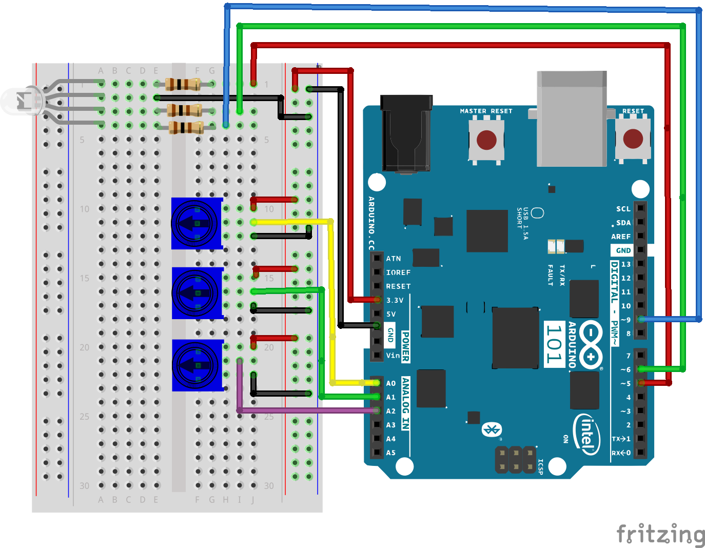
Ready to start hooking everything up? Check out the wiring diagram and hookup table below to see how everything is connected.
| Polarized Components | Pay special attention to the component’s markings indicating how to place it on the breadboard. Polarized components can only be connected to a circuit in one direction. Polarized components are highlighted with a yellow warning triangle in the table below. |
**Please note: Pay close attention to the LED. The negative side of the LED is the short leg, marked with a flat edge. **
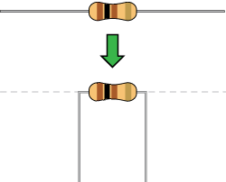
Components like resistors need to have their legs bent into 90° angles in order to correctly fit the breadboard sockets. You can also cut the legs shorter to make them easier to work with on the breadboard.
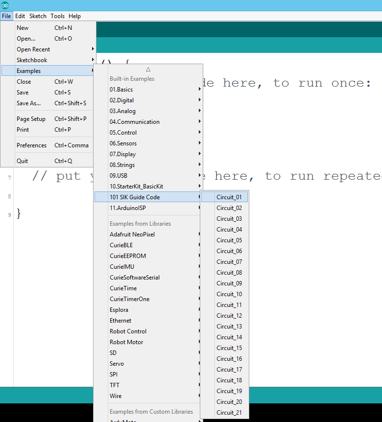
Open the Arduino IDE software on your computer. Coding in the Arduino language will control your circuit. Open the code for Circuit 1 by accessing the “101 SIK Guide Code” you downloaded and placed into your “Examples” folder earlier.
To open the code go to: File > Examples > 101 SIK Guide Code > Circuit_01
You can also copy and paste the following code into the Arduino IDE. Hit upload, and see what happens!
language:cpp
/*
SparkFun Inventor's Kit for the Arduino / Genuino 101
Example sketch 01

BLINKING AN LED

Turn an LED on for one second, off for one second,
and repeat forever.

This sketch was written by SparkFun Electronics,
with lots of help from the Arduino community.
This code is completely free for any use.
Visit http://learn.sparkfun.com/products/2 for SIK information.
Visit http://www.arduino.cc to learn about Arduino.
*/


//The setup function runs once upon your Arduino being powered or once upload is          //complete.

void setup()
{
  //set pin 13 to OUTPUT
  pinMode(13, OUTPUT);
}

//The loop function runs from the top down and repeats itself until you upload new        //code or power down your Arduino
void loop()
{
  //Turn pin 13 HIGH (ON).
  digitalWrite(13, HIGH);

  //wait 1000 milliseconds (1 second)
  delay(1000);

  //Turn pin 13, LOW (OFF)
  digitalWrite(13, LOW);

  //wait 1000 milliseconds
  delay(1000);
}
pinMode(13, OUTPUT);
Before you can use one of the 101's pins, you need to tell the board whether it is an INPUT or OUTPUT. We use a built-in "function" called pinMode() to do this.
digitalWrite(13, HIGH);
When you're using a pin as an OUTPUT, you can command it to be HIGH (output 3.3 volts), or LOW (output 0 volts).
You should see your LED blink on and off. If it doesn't, make sure you have assembled the circuit correctly and verified and uploaded the code to your board, or see the Troubleshooting section.

This happens sometimes; the most likely cause is a confused serial port. You can change this in Tools > Serial Port >
Also, if you get a Timeout error or the IDE could not find your 101 board, try pressing the Master Reset button on the 101, wait around 10 seconds and try re-uploading your sketch.
In this circuit you will work with a potentiometer. You will learn how to use a potentiometer to control the timing of a blinking LED by reading a sensor and storing it as a variable, then using it as your delay timing.
You will need the following parts:
If you are conducting this experiment and didn't get the SIK, we suggest using these parts:
You will also need either an Arduino 101 OR Genuino 101 board.
Before continuing with this experiment, we recommend you be familiar with the concepts in the following tutorial:
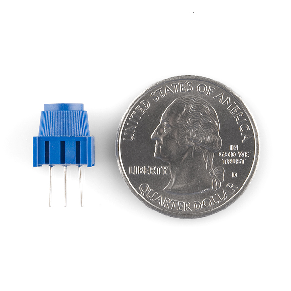
A potentiometer is a resistance-based analog sensor that changes its internal resistance based on the rotation of its knob. The potentiometer has an internal voltage divider enabling you to read the change in voltage on the center pin with a microcontroller (the 101 board). To hook up the potentiometer, attach the two outside pins to a supply voltage (3.3V in this circuit) and ground. It doesn’t matter which is connected where, as long as one is connected to power, and the other to ground. The center pin is then connected to an analog input pin so the 101 can measure the change in voltage. When you twist the knob, the sensor reading will change!
**Note: The potentiometer included in the kit has three marks on it that will help you figure out which breadboard rows the pins are plugged into. **
Ready to start hooking everything up? Check out the wiring diagram and hookup table below to see how everything is connected.
| Polarized Components | Pay special attention to the component’s markings indicating how to place it on the breadboard. Polarized components can only be connected to a circuit in one direction. Polarized components are highlighted with a yellow warning triangle in the table. |

Open the Arduino IDE software on your computer. Coding in the Arduino language will control your circuit. Open the code for Circuit 2 by accessing the “101 SIK Guide Code” you downloaded and placed into your “Examples” folder earlier.
To open the code go to: File > Examples > 101 SIK Guide Code > Circuit_02
**Copy and paste the following code into the Arduino IDE. Hit upload, and see what happens! **
language:cpp
/* SparkFun Inventor's Kit
Example sketch 02

POTENTIOMETER

  Measure the position of a potentiometer and use it to
  control the blink rate of an LED. Turn the knob to make
  it blink faster or slower!

This sketch was written by SparkFun Electronics,
with lots of help from the Arduino community.
This code is completely free for any use.
Visit http://learn.sparkfun.com/products/2 for SIK information.
Visit http://www.arduino.cc to learn about Arduino.
*/


//Create global variables (variables that can be used anywhere in our sketch)

// Here we're creating a variable called "sensorPin" of type "int"
// and initializing it to have the value "0," which is the analog input pin the pot is     //conected to.
int sensorPin = 0;

// Variable for storing the pin number that the LED is connected to
int ledPin = 13;

// this function runs once when the sketch starts up
void setup()
{
  //set ledPin (13) as an OUTPUT
  pinMode(ledPin, OUTPUT);
}

// this function runs repeatedly after setup() finishes
void loop()
{

  //create a local variable (variable that can only be used inside of loop() to store       //a sensor value called sensorValue
  int sensorValue;

  //use the analogRead() function to read sensorPin and store the value in sensorValue
  sensorValue = analogRead(sensorPin);

  // Turn the LED on
  digitalWrite(ledPin, HIGH);


  delay(sensorValue);

  // Turn the LED off
  digitalWrite(ledPin, LOW);

 //delay for the value of sensorValue
  delay(sensorValue);

  //loop back to the top
}
int sensorValue;
A “variable” is a placeholder for values that may change in your code. You must introduce, or "declare," variables before you use them; here you are declaring a variable called sensorValue, of type "int" (integer). Don't forget that variable names are case sensitive!
sensorValue = analogRead(sensorPin);
Use the analogRead() function to read the value on an analog pin. analogRead() takes one parameter, the analog pin you want to use ("sensorPin"), and returns a number ("sensorValue") between 0 (0 volts) and 1023 (3.3 volts).
delay(sensorValue);
Microcontrollers are very fast, capable of running thousands of lines of code each second. To slow it down so that we can see what it's doing, we'll often insert delays into the code. delay() counts in milliseconds; there are 1000 ms in one second.
You should see the LED blink faster or slower in accordance with your potentiometer. If it isn't working, make sure you have assembled the circuit correctly and verified and uploaded the code to your board, or see the Troubleshooting section.
This is most likely due to a slightly dodgy connection with the potentiometer's pins. This can usually be conquered by holding the potentiometer down or moving the potentiometer circuit somewhere else on your breadboard.
Make sure you haven’t accidentally connected the wiper (center pin), the resistive element in the potentiometer, to digital pin 0 rather than analog pin 0 (the row of pins beneath the power pins).
LEDs will only work in one direction. Double check your connections.
You know what’s even more fun than a blinking LED? Changing colors with one LED. In this circuit, you’ll learn how to use an RGB LED to create unique color combinations. Depending on how bright each diode is, nearly any color is possible!
You will need the following parts:
If you are conducting this experiment and didn't get the SIK, we suggest using these parts:
You will also need either an Arduino 101 OR Genuino 101 board.
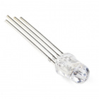
The Red Green Blue (RGB) LED is 3 LEDs in one. The RGB has four pins with each of the three shorter pins controlling an individual color: red, green or blue. The longer pin of the RGB is the common ground pin. You can create a custom colored LED by turning different colors on and off to combine them. For example, if you turn on the red pin and green pin, the RGB will light up as yellow.
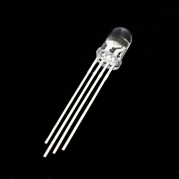
But which pin is which color? Pick up the RGB so that the longest pin (common ground) is aligned to the left as shown in the graphic below. The pins are Red, Ground, Green, and Blue -- starting from the far left.
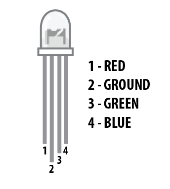
**Note: When wiring the RGB, each colored pin still needs a current-limiting resistor in-line with the I/O pin that you plan to use to control it, as with any standard LED. **
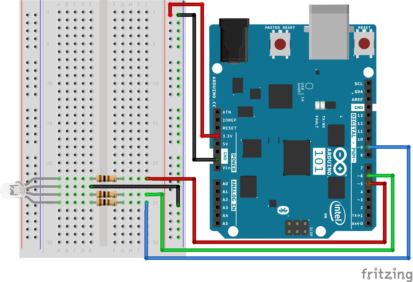
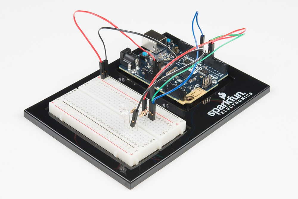
Ready to start hooking everything up? Check out the wiring diagram and hookup table below to see how everything is connected.
| Polarized Components | Pay special attention to the component’s markings indicating how to place it on the breadboard. Polarized components can only be connected to a circuit in one direction. Polarized components are highlighted with a yellow warning triangle in the table below. |
Open the Arduino IDE software on your computer. Coding in the Arduino language will control your circuit. Open the code for Circuit 3 by accessing the “101 SIK Guide Code” you downloaded and placed into your “Examples” folder earlier.
To open the code go to: File > Examples >101 SIK Guide Code > Circuit_03
You can also copy and paste the following code into the Arduino IDE. Hit upload, and see what happens!
language:cpp
/*
SparkFun Inventor's Kit
Example sketch 03

RGB LED

Make an RGB LED display a rainbow of colors!


This sketch was written by SparkFun Electronics,
with lots of help from the Arduino community.
Visit http://learn.sparkfun.com/products/2 for SIK information.
Visit http://www.arduino.cc to learn about the Arduino.
*/

//create variables for pin numbers. We are making them constants here, because they       //never change.
const int RED_PIN = 5;
const int GREEN_PIN = 6;
const int BLUE_PIN = 9;

// How fast we plan to cycle through colors in milliseconds
int DISPLAY_TIME = 10;


void setup()
{
//set the three pin variables as outputs
pinMode(RED_PIN, OUTPUT);
pinMode(GREEN_PIN, OUTPUT);
pinMode(BLUE_PIN, OUTPUT);
}


void loop()
{
// We've written a custom function called mainColors() that steps
// through all eight of these colors. We're only "calling" the
// function here (telling it to run). The actual function code
// is further down in the sketch.
mainColors();


}


// Here's the mainColors() custom function we've written.
void mainColors()
{
// Off (all LEDs off):
digitalWrite(RED_PIN, LOW);
digitalWrite(GREEN_PIN, LOW);
digitalWrite(BLUE_PIN, LOW);

//wait 1 second
delay(1000);

// Red (turn just the red LED on):
digitalWrite(RED_PIN, HIGH);
digitalWrite(GREEN_PIN, LOW);
digitalWrite(BLUE_PIN, LOW);

//wait 1 seconds
delay(1000);

// Green (turn just the green LED on):
digitalWrite(RED_PIN, LOW);
digitalWrite(GREEN_PIN, HIGH);
digitalWrite(BLUE_PIN, LOW);

//wait 1 second
delay(1000);

// Blue (turn just the blue LED on):
digitalWrite(RED_PIN, LOW);
digitalWrite(GREEN_PIN, LOW);
digitalWrite(BLUE_PIN, HIGH);

//wait 1 second
delay(1000);

// Yellow (turn red and green on):
digitalWrite(RED_PIN, HIGH);
digitalWrite(GREEN_PIN, HIGH);
digitalWrite(BLUE_PIN, LOW);

//wait 1 second
delay(1000);

// Cyan (turn green and blue on):
digitalWrite(RED_PIN, LOW);
digitalWrite(GREEN_PIN, HIGH);
digitalWrite(BLUE_PIN, HIGH);

//wait 1 second
delay(1000);

// Purple (turn red and blue on):
digitalWrite(RED_PIN, HIGH);
digitalWrite(GREEN_PIN, LOW);
digitalWrite(BLUE_PIN, HIGH);

//wait 1 second
delay(1000);

// White (turn all the LEDs on):
digitalWrite(RED_PIN, HIGH);
digitalWrite(GREEN_PIN, HIGH);
digitalWrite(BLUE_PIN, HIGH);

//wait 1 second
delay(1000);
}
language:cpp
for (x = 0; x < 768; x++)
{}
A for() loop is used to repeat an action a set number of times across a range, and repeatedly runs code within the brackets {}. Here the variable "x" starts a 0, ends at 767, and increases by one each time ("x++").
language:cpp
if (x <= 255)
{}
else
{}
"If / else" statements are used to make choices in your programs. The statement within the parenthesis () is evaluated; if it's true, the code within the first brackets {} will run. If it's not true, the code within the second brackets {} will run.
You should see your LED turn on, but this time in new, crazy colors! If it isn't, make sure you have assembled the circuit correctly and verified and uploaded the code to your board, or see the Troubleshooting section.
With the four pins of the LED so close together, it’s sometimes easy to misplace one. Double check each pin is where it should be.
The red diode within the RGB LED may be a bit brighter than the other two. To make your colors more balanced, use a higher ohm resistor.
Now that you've gotten your LED to blink on and off, it's time to up the stakes a little bit – by connecting six LEDs at once. We'll also give your 101 board a little test by creating various lighting sequences. This experiment is a great setup to start practicing writing your own programs and getting a feel for the way your 101 board works.
Along with controlling the LEDs, you’ll learn a few programming tricks that keep your code neat and tidy!
You will need the following parts:
If you are conducting this experiment and didn't get the SIK, we suggest using these parts:
You will also need either an Arduino 101 OR Genuino 101 board.
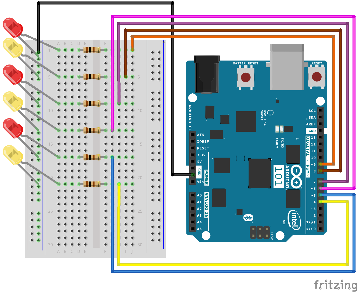
Ready to start hooking everything up? Check out the wiring diagram and hookup table below to see how everything is connected.
| Polarized Components | Pay special attention to the component’s markings indicating how to place it on the breadboard. Polarized components can only be connected to a circuit in one direction. |
Open the Arduino IDE software on your computer. Coding in the Arduino language will control your circuit. Open the code for Circuit 4 by accessing the “101 SIK Guide Code” you downloaded and placed into your “Examples” folder earlier.
To open the code go to: File > Examples > 101 SIK Guide Code > Circuit_04
You can also copy and paste the following code into the Arduino IDE. Hit upload, and see what happens!
language:cpp
/*
SparkFun Inventor's Kit
Example sketch 04

MULTIPLE LEDs

  Make six LEDs dance. Dance LEDs, dance!


This sketch was written by SparkFun Electronics,
with lots of help from the Arduino community.
This code is completely free for any use.
Visit http://learn.sparkfun.com/products/2 for SIK information.
Visit http://www.arduino.cc to learn more about Arduino.
*/


// To keep track of all the LED pins, we'll use an "array."
// An array lets you store a group of variables, and refer to them
// by their position, or "index." Here we're creating an array of
// six integers, and initializing them to a set of values:
int ledPins[] = {4,5,6,7,8,9};


void setup()
{
  //create a local variable to store the index of which pin we want to control
  int index;


  // For the for() loop below, these are the three statements:

  //   1. index = 0;    Before starting, make index = 0.
  //   2. index <= 5;   If index is less or equal to 5, run the following code
  //   3. index++   Putting "++" after a variable means "add one to it".

  // When the test in statement 2 is finally false, the sketch
  // will continue.

  // This for() loop will make index = 0, then run the pinMode()
  // statement within the brackets. It will then do the same thing
  // for index = 2, index = 3, etc. all the way to index = 5.

  for(index = 0; index <= 5; index++)
  {
    pinMode(ledPins[index],OUTPUT);
  }
}


void loop()
{
  // This loop() calls functions that we've written further below.
  // We've disabled some of these by commenting them out (putting
  // "//" in front of them). To try different LED displays, remove
  // the "//" in front of the ones you'd like to run, and add "//"
  // in front of those you don't to comment out (and disable) those
  // lines.

  // Light up all the LEDs in turn
  oneAfterAnotherNoLoop();

  // Same as oneAfterAnotherNoLoop, but less typing
  //oneAfterAnotherLoop();

  // Turn on one LED at a time, scrolling down the line
  //oneOnAtATime();

  // Light the LEDs middle to the edges
  //pingPong();

  // Chase lights like you see on signs
  //marquee();

  // Blink LEDs randomly
  //randomLED();
}


/*
oneAfterAnotherNoLoop()
This function will light one LED, delay for delayTime, then light
the next LED, and repeat until all the LEDs are on. It will then
turn them off in the reverse order.
*/

void oneAfterAnotherNoLoop()
{
// time (milliseconds) to pause between LEDs
  int delayTime = 100;


  // turn all the LEDs on:

  digitalWrite(ledPins[0], HIGH);  //Turns on LED #0 (pin 4)
  delay(delayTime);                //wait delayTime milliseconds
  digitalWrite(ledPins[1], HIGH);  //Turns on LED #1 (pin 5)
  delay(delayTime);                //wait delayTime milliseconds
  digitalWrite(ledPins[2], HIGH);  //Turns on LED #2 (pin 6)
  delay(delayTime);                //wait delayTime milliseconds
  digitalWrite(ledPins[3], HIGH);  //Turns on LED #3 (pin 7)
  delay(delayTime);                //wait delayTime milliseconds
  digitalWrite(ledPins[4], HIGH);  //Turns on LED #4 (pin 8)
  delay(delayTime);                //wait delayTime milliseconds
  digitalWrite(ledPins[5], HIGH);  //Turns on LED #5 (pin 9)
  delay(delayTime);                //wait delayTime milliseconds

  // turn all the LEDs off:

  digitalWrite(ledPins[5], LOW);   //Turn off LED #5 (pin 9)
  delay(delayTime);                //wait delayTime milliseconds
  digitalWrite(ledPins[4], LOW);   //Turn off LED #4 (pin 8)
  delay(delayTime);                //wait delayTime milliseconds
  digitalWrite(ledPins[3], LOW);   //Turn off LED #3 (pin 7)
  delay(delayTime);                //wait delayTime milliseconds
  digitalWrite(ledPins[2], LOW);   //Turn off LED #2 (pin 6)
  delay(delayTime);                //wait delayTime milliseconds
  digitalWrite(ledPins[1], LOW);   //Turn off LED #1 (pin 5)
  delay(delayTime);                //wait delayTime milliseconds
  digitalWrite(ledPins[0], LOW);   //Turn off LED #0 (pin 4)
  delay(delayTime);                //wait delayTime milliseconds
}


/*
oneAfterAnotherLoop()

This function does exactly the same thing as oneAfterAnotherNoLoop(),
but it takes advantage of for() loops and the array to do it with
much less typing.
*/

void oneAfterAnotherLoop()
{
  int index;
  int delayTime = 100; // milliseconds to pause between LEDs
                       // make this smaller for faster switching

  // Turn all the LEDs on:

  // This for() loop will step index from 0 to 5
  // (putting "++" after a variable means add one to it)
  // and will then use digitalWrite() to turn that LED on.

  for(index = 0; index <= 5; index++)
  {
    digitalWrite(ledPins[index], HIGH);
    delay(delayTime);
  }

  // Turn all the LEDs off:

  // This for() loop will step index from 5 to 0
  // (putting "--" after a variable means subtract one from it)
  // and will then use digitalWrite() to turn that LED off.

  for(index = 5; index >= 0; index--)
  {
    digitalWrite(ledPins[index], LOW);
    delay(delayTime);
  }
}


/*
oneOnAtATime()

This function will step through the LEDs,
lighting only one at at time.
*/

void oneOnAtATime()
{
  int index;
  int delayTime = 100; // milliseconds to pause between LEDs
                       // make this smaller for faster switching

  // step through the LEDs, from 0 to 5

  for(index = 0; index <= 5; index++)
  {
    digitalWrite(ledPins[index], HIGH);  // turn LED on
    delay(delayTime);                    // pause to slow down
    digitalWrite(ledPins[index], LOW);   // turn LED off
  }
}


/*
pingPong()

This function will step through the LEDs,
lighting one at at time in both directions.
*/

void pingPong()
{
  int index;
  int delayTime = 100; // milliseconds to pause between LEDs
                       // make this smaller for faster switching

  // step through the LEDs, from 0 to 5

  for(index = 0; index <= 5; index++)
  {
    digitalWrite(ledPins[index], HIGH);  // turn LED on
    delay(delayTime);                    // pause to slow down
    digitalWrite(ledPins[index], LOW);   // turn LED off
  }

  // step through the LEDs, from 5 to 0

  for(index = 5; index >= 0; index--)
  {
    digitalWrite(ledPins[index], HIGH);  // turn LED on
    delay(delayTime);                    // pause to slow down
    digitalWrite(ledPins[index], LOW);   // turn LED off
  }
}


/*
marquee()

This function will mimic "chase lights" like those around signs.
*/

void marquee()
{
  int index;
  int delayTime = 200; // milliseconds to pause between LEDs
                       // Make this smaller for faster switching

  // Step through the first four LEDs
  // (We'll light up one in the lower 3 and one in the upper 3)

  for(index = 0; index <= 2; index++) // Step from 0 to 3
  {
    digitalWrite(ledPins[index], HIGH);    // Turn a LED on
    digitalWrite(ledPins[index+3], HIGH);  // Skip four, and turn that LED on
    delay(delayTime);                      // Pause to slow down the sequence
    digitalWrite(ledPins[index], LOW);     // Turn the LED off
    digitalWrite(ledPins[index+3], LOW);   // Skip four, and turn that LED off
  }
}


/*
randomLED()

This function will turn on random LEDs. Can you modify it so it
also lights them for random times?
*/

void randomLED()
{
  int index;
  int delayTime;

  // The random() function will return a semi-random number each
  // time it is called. See http://arduino.cc/en/Reference/Random
  // for tips on how to make random() even more random.

  index = random(5);    // pick a random number between 0 and 5
  delayTime = 100;

  digitalWrite(ledPins[index], HIGH);  // turn LED on
  delay(delayTime);                    // pause to slow down
  digitalWrite(ledPins[index], LOW);   // turn LED off
}
int ledPins[] = {4,5,6,7,8,9};
When you have to manage a lot of variables, an "array" is a handy way to group them together. Here we're creating an array of integers, called ledPins, with six elements. Each element is referenced by its index. The first element is the index of [0].
digitalWrite(ledPins[0], HIGH);
You refer to the elements in an array by their position. The first element is at position 0, the second is at position 1, etc. You refer to an element using "ledPins[x]" where x is the position. Here we're making digital pin 4 HIGH, since the array element at position 0 is "4."
index = random(5);
Computers like to do the same things each time they run. But sometimes you want to do things randomly, such as simulating the roll of a dice. The random() function is a great way to do this.
See http://arduino.cc/en/reference/random for more information.
This is similar to Experiment 1, but instead of one LED, you should see all the LEDs blink. If they don't, make sure you have assembled the circuit correctly and verified and uploaded the code to your board, or see the Troubleshooting section.
It is easy to insert an LED backward. Check the LEDs that aren't working and ensure they are in the correct orientation.
With eight wires it's easy to cross a couple. Double check that the first LED is plugged into pin 4 and each pin thereafter.
It’s easy to accidentally misplace a wire without noticing. Pulling everything out and starting with a fresh slate is often easier than trying to track down the problem.
Up until now, we’ve focused mostly on outputs. Now we’re going to go to the other end of spectrum and play around with inputs. In Experiment 2, we used an analog input to read the potentiometer. In this experiment, we’ll be reading one of the most common and simple inputs – a push button – by using a digital input. We will use it to cycle through different colors on the RGB.
You will need the following parts:
If you are conducting this experiment and didn't get the SIK, we suggest using these parts:
You will also need either an Arduino 101 OR Genuino 101 board.
Before continuing with this tutorial, we recommend you be somewhat familiar with the concepts in these tutorials:
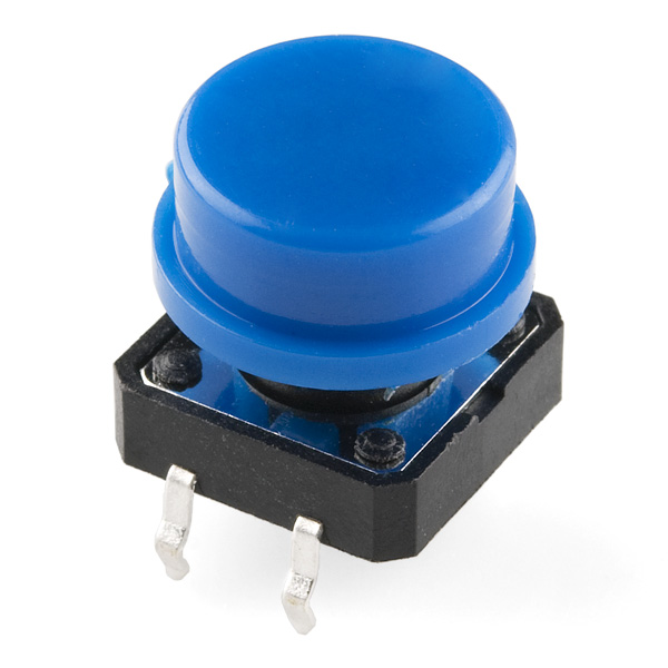
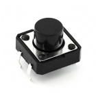
A momentary push button closes or completes the circuit only while it is being pressed. The button has four pins, which are broken out into two sets of two pins. When you press down on the button and get a nice "click," the button bridges the two sets of pins and allows current to flow through the circuit.
How do you know which pins are paired up? The buttons included in this kit will only fit across the breadboard ditch in one direction. Once you get the button pressed firmly into the breadboard (across the ditch), the pins are horizontally paired. The pins toward the top of the breadboard are connected, and the pins toward the button of the breadboard are connected.
Note: Not all buttons share this pin format. Please refer to the data sheet of your specific button to determine which pins are paired up.
Ready to start hooking everything up? Check out the wiring diagram and hookup table below to see how everything is connected.
| Polarized Components | Pay special attention to the component’s markings indicating how to place it on the breadboard. Polarized components can only be connected to a circuit in one direction. |
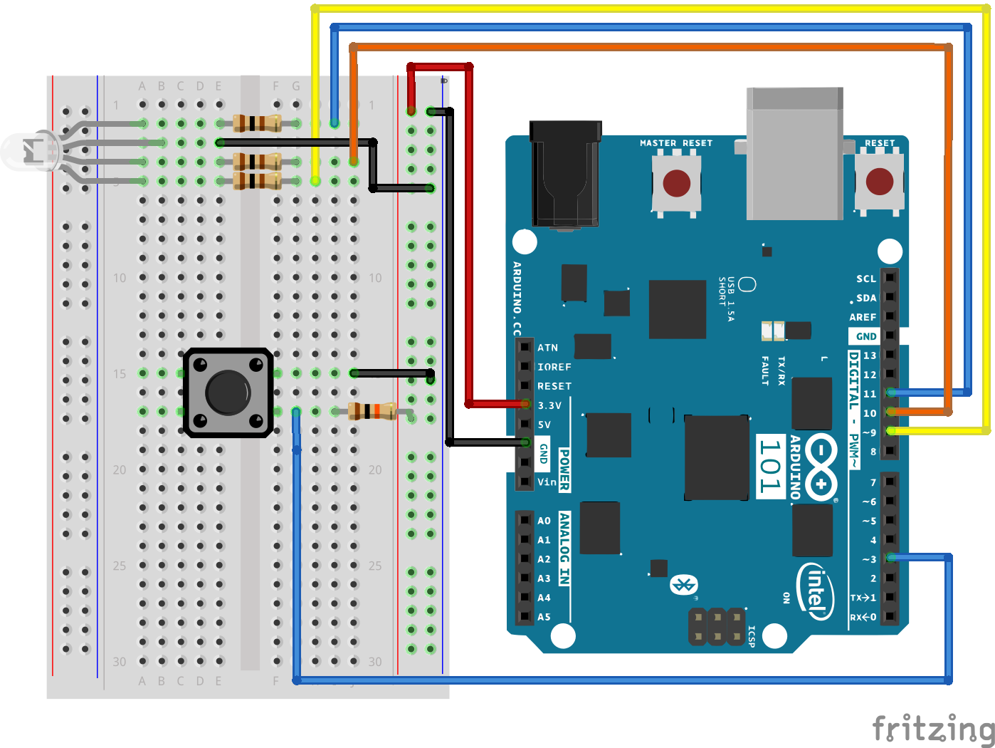
Previously we've used the analog pins for input; now we'll use the digital pins for input as well. Because digital pins only know about HIGH and LOW signals, they're perfect for interfacing to pushbuttons and switches that also only have "on" and "off" states.
We'll connect one side of the pushbutton to ground, and the other side to a digital pin. When we press down on the pushbutton, the pin will be connected to ground, and therefore will be read as "LOW" by the Arduino board.
But wait -- what happens when you're not pushing the button? In this state, the pin is disconnected from everything, which we call "floating." What will the pin read as then, HIGH or LOW? It's hard to say, because there's no solid connection to either 3.3V or ground. The pin could read as either one.
To deal with this issue, we'll connect a small (10K, or 10,000 Ohm) resistance between the signal pin and 3.3V. This "pullup" resistor will ensure that when you're NOT pushing the button, the pin will still have a weak connection to 3.3 volts, and therefore read as HIGH.
Advanced: When you get used to pullup resistors and know when they're required, you can activate internal pullup resistors on the ATmega processor in Arduino. See http://arduino.cc/en/Tutorial/DigitalPins for information.
Open the Arduino IDE software on your computer. Coding in the Arduino language will control your circuit. Open the code for Circuit 5 by accessing the “101 SIK Guide Code” you downloaded and placed into your “Examples” folder earlier.
To open the code go to: File > Examples > 101 SIK Guide Code > Circuit_05
You can also copy and paste the following code into the Arduino IDE. Hit upload, and see what happens!
language:cpp
/*
SparkFun Inventor's Kit
Example sketch 05

PUSH BUTTONS

  Use pushbuttons for digital input

This sketch was written by SparkFun Electronics,
with lots of help from the Arduino community.
This code is completely free for any use.
Visit http://learn.sparkfun.com/products/2 for SIK information.
Visit http://www.arduino.cc to learn about the Arduino.

*/


// First we'll set up constants for the pin numbers.
// This will make it easier to follow the code below.

 // pushbutton pin
 const int buttonPin = 3;

 //RGB LED pins
 const int redPin = 11;
 const int greenPin = 10;
 const int bluePin = 9;


//create a variable to store a counter and set it to 0
int counter = 0;
void setup()
{
  // Set up the pushbutton pins to be an input:
  pinMode(buttonPin, INPUT);

  // Set up the RGB pins to be an outputs:
  pinMode(redPin, OUTPUT);
  pinMode(greenPin,OUTPUT);
  pinMode(bluePin,OUTPUT);
}


void loop()
{
 // local variable to hold the pushbutton states
  int buttonState;

  //read the digital state of buttonPin with digitalRead() function and store the           //value in buttonState variable
  buttonState = digitalRead(buttonPin);

  //if the button is pressed increment counter and wait a tiny bit to give us some          //time to release the button
  if (buttonState == LOW) // light the LED
  {
    counter++;
    delay(150);
  }

  //use the if satement to check the value of counter. If counter is equal to 0 all         //pins are off
  if(counter == 0)
  {
   digitalWrite(redPin,LOW);
   digitalWrite(greenPin,LOW);
   digitalWrite(bluePin,LOW);
  }

  //else if counter is equal to 1, redPin is HIGH
  else if(counter == 1)
  {
   digitalWrite(redPin,HIGH);
   digitalWrite(greenPin,LOW);
   digitalWrite(bluePin,LOW);
  }

  //else if counter is equal to 2 greenPin is HIGH
  else if(counter ==2)
  {
   digitalWrite(redPin,LOW);
   digitalWrite(greenPin,HIGH);
   digitalWrite(bluePin,LOW);
  }

  //else if counter is equal to 3 bluePin is HIGH
  else if(counter ==3)
  {
   digitalWrite(redPin,LOW);
   digitalWrite(greenPin,LOW);
   digitalWrite(bluePin,HIGH);
  }

  //else reset the counter to 0 (which turns all pins off)
  else
  {
   counter =0;
  }
}
pinMode(buttonPin, INPUT);
The digital pins can be used as inputs as well as outputs. Before you do either, you need to tell the Arduino which direction you're going.
buttonState = digitalRead(buttonPin);
To read a digital input, you use the digitalRead() function. It will return HIGH if there's 3.3V present at the pin, or LOW if there's 0V present at the pin.
if (button1State == LOW)
Because we've connected the button to GND, it will read LOW when it's being pressed. Here we're using the "equivalence" operator ("==") to see if the button is being pressed.
You should see the RGB LED light up a different color (red, green, blue) every time you press down on the button. The button will turn off the LED on the fourth button press. (See the code to find out why!) If it isn't working, make sure you have assembled the circuit correctly and verified and uploaded the code to your board or see the troubleshooting section.

The pushbutton is square, and because of this it is easy to put it in the wrong way. Give it a 90 degree twist and see if it starts working.
No worries; these circuits are all super stripped-down to make playing with the components easy, but once you throw them together the sky is the limit.
In the previous experiment you used a button as a digital input. In this experiment you are going to explore another digital input, the SPDT (Single Pole - Double Throw) switch. You will use that switch to select which of the two LEDs will blink.
You will need the following parts:
If you are conducting this experiment and didn't get the SIK, we suggest using these parts:
You will also need either an Arduino 101 OR Genuino 101 board.
Before continuing with this tutorial, we recommend you be somewhat familiar with the concepts in these tutorials:

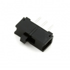
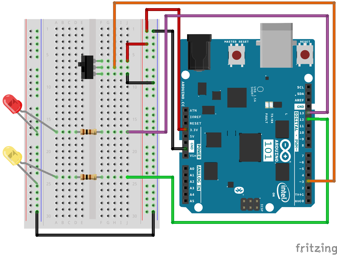
The Single Pole - Double Throw (SPDT) switch has a common pin in the middle and then two other pins that, depending on the location of the switch, are either connected to the common (center) pin or not. To read the switch in a similar way to a button, you connected the common pin to a digital General Purpose Input/Output (GPIO) pin on your 101 board and the other pins to 3.3V and ground. It doesn’t matter which pin is which. When you move the switch, the common pin will either be HIGH (connected to 3.3V) or LOW (connected to ground).
Ready to start hooking everything up? Check out the wiring diagram and hookup table below, to see how everything is connected.
| Polarized Components | Pay special attention to the component’s markings indicating how to place it on the breadboard. Polarized components can only be connected to a circuit in one direction. |
Open the Arduino IDE software on your computer. Coding in the Arduino language will control your circuit. Open the code for Circuit 6 by accessing the “101 SIK Guide Code” you downloaded and placed into your “Examples” folder earlier.
To open the code go to: File > Examples > 101 SIK Guide Code > Circuit_06
You can also copy and paste the following code into the Arduino IDE. Hit upload, and see what happens!
language:cpp
/*
SparkFun Inventor's Kit
Example sketch 06

SPDT Switch

Use a Single Pole - Double Throw Switch (SPDT) to select an LED to blink

This sketch was written by SparkFun Electronics,
with lots of help from the Arduino community.
This code is completely free for any use.
Visit http://learn.sparkfun.com/products/2 for SIK information.
Visit http://www.arduino.cc to learn more about Arduino.
*/


// Create constants for the pins we will be using
const int switchPin = 3;
const int led1Pin = 12;
const int led2Pin =  13;


void setup()
{
  // Set up the switch pins to be an input:
  pinMode(switchPin, INPUT);

  // Set up the LED pins to be an output:
  pinMode(led1Pin,OUTPUT);
  pinMode(led2Pin,OUTPUT);
}


void loop()
{
  // variables to hold the switch state
  int switchVal;

  // Since a switch has only two states, either HIGH (3.3V)
  // or LOW (GND) there is no way for you to have a floating point situation so there       //is no need for a pulldown resistor.

  //store the switch value to the switchVal variable
  switchVal = digitalRead(switchPin);

 //if switchVal is HIGH blink led1Pin
 if(switchVal == HIGH)
 {
   digitalWrite(led1Pin,HIGH);
   delay(500);
   digitalWrite(led1Pin,LOW);
   delay(500);
 }
 //else blink led2Pin
 else
 {
   digitalWrite(led2Pin,HIGH);
   delay(500);
   digitalWrite(led2Pin,LOW);
   delay(500);
 }
}
pinMode(switchPin, INPUT);
The digital pins can be used as inputs as well as outputs. Before you do either, you need to tell the Arduino 101 which direction you're going.
switchVal = digitalRead(switchPin);
To read a digital input, you use the digitalRead() function. It will return HIGH if there's 3.3V present at the pin, or LOW if there's 0V present at the pin.
if (switchVal == LOW)
Because we've connected the button to GND, it will read LOW when it's being pressed. Here we're using the "equivalence" operator ("==") to see if the button is being pressed.
Depending on the state of the switch, a different LED will blink. If you move the switch to connect the signal pin to 3.3V (HIGH) then LED 1 will blink. If you flip the switch and ground the signal pin then LED 2 will start blinking and LED 1 will turn off.
The wires for the switch are right next to each other. Make sure that signal is in the center with voltage and ground on the outside pins. If you connect ground and voltage your board will short out and shut down.
Make sure your power LED is on. If it is off, pull the signal wire from pin 3 and see if that changes anything. If you short circuit your 101 board it will turn itself off to protect the circuitry. You may also have to restart your computer to regain access to your serial port.
No worries; these circuits are all super stripped-down to make playing with the components easy, but once you throw them together the sky is the limit.
In Experiment 2, you got to use a potentiometer, which varies resistance based on the twisting of a knob and, in turn, changes the voltage being read by the analog input pin. In this circuit you’ll be using a photoresistor, which changes resistance based on how much light the sensor receives. You will read the light value of the room and have an LED turn on if it is dark and turn off if it is bright. That's right; you are going to build a night light!
You will need the following parts:
If you are conducting this experiment and didn't get the SIK, we suggest using these parts:
You will also need either an Arduino 101 OR Genuino 101 board.
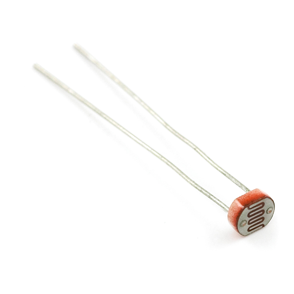
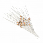
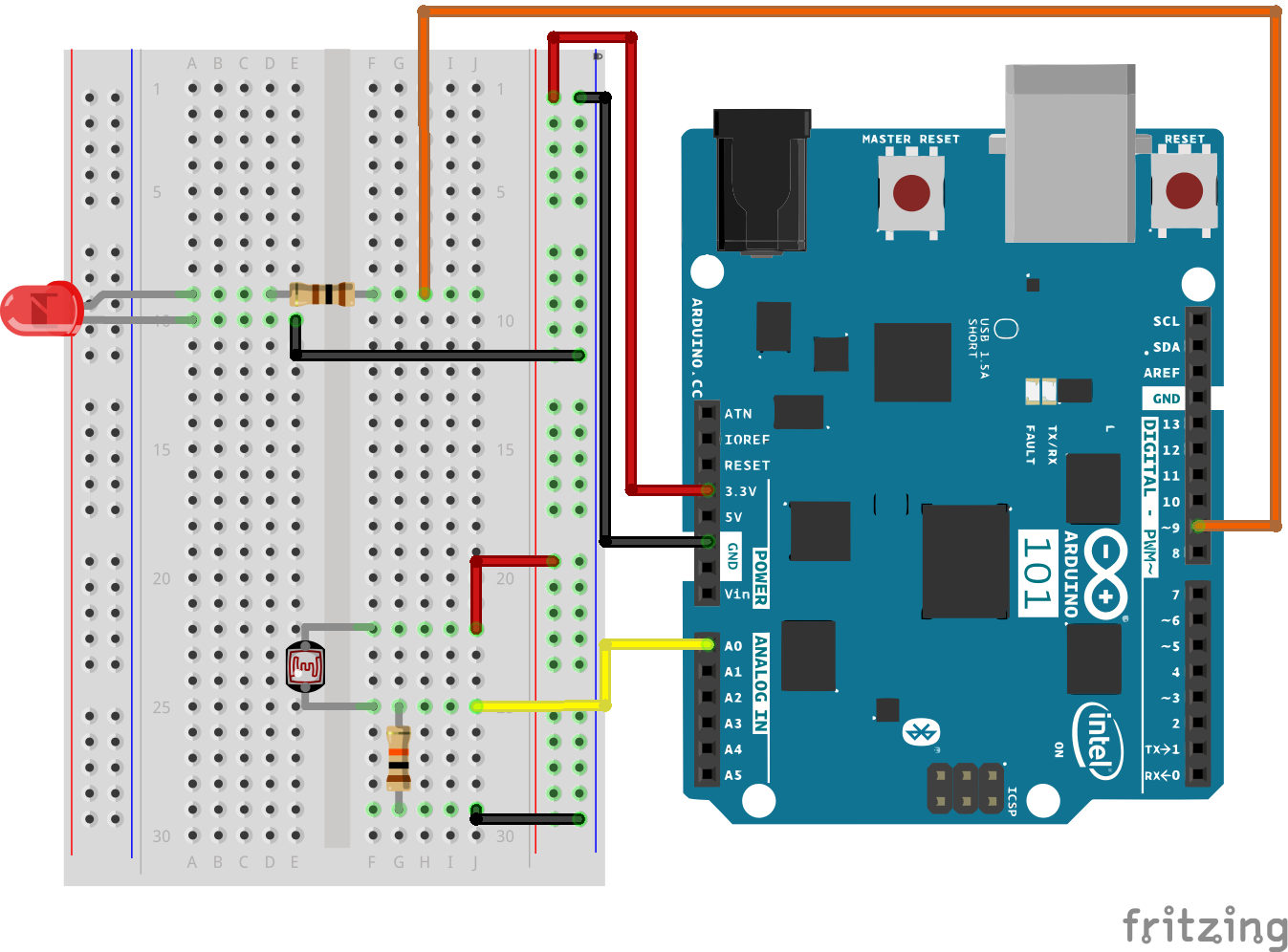
The photoresistor changes its resistance based on the light to which it is exposed. To use this with the 101 board, you will need to build a voltage divider with a 10K Ohm resistor as shown in the wiring diagram for this experiment. The 101 board cannot read a change in resistance, only a change in voltage. A voltage divider allows you to translate a change in resistance to a corresponding voltage value.
The voltage divider enables the use of resistance-based sensors like the photoresistor in a voltage-based system. As you explore different sensors, you will find more resistance-based sensors that only have two pins like the photoresistor. To use them with your 101 board you will need to build a voltage divider like the one in this experiment. To learn more about resistors in general, check out our tutorial on resistors and also our tutorial on voltage dividers.
Note: Make sure you are using the 10K Ohm resistor in your voltage divider with the sensors in this kit. Otherwise you will get odd and inconsistent results.
Ready to start hooking everything up? Check out the wiring diagram below to see how everything is connected.
| Polarized Components | Pay special attention to the component’s markings indicating how to place it on the breadboard. Polarized components can only be connected to a circuit in one direction. |
Open the Arduino IDE software on your computer. Coding in the Arduino language will control your circuit. Open the code for Circuit 7 by accessing the “101 SIK Guide Code” you downloaded and placed into your “Examples” folder earlier.
To open the code go to: File > Examples > 101 SIK Guide Code > Circuit_07
You can also copy and paste the following code into the Arduino IDE. Hit upload, and see what happens!
language:cpp
/*
SparkFun Inventor's Kit
Example sketch 07

PHOTORESISTOR

  Read a photoresistor (light sensor) to detect "darkness" and turn on an LED when it is "dark" and turn back off again when it is "bright."

This sketch was written by SparkFun Electronics,
with lots of help from the Arduino community.
This code is completely free for any use.
Visit http://learn.sparkfun.com/products/2 for SIK information.
Visit http://www.arduino.cc to learn more about Arduino.
*/


// As usual, we'll create constants to name the pins we're using.
// This will make it easier to follow the code below.

const int sensorPin = 0;
const int ledPin = 9;

// We'll also set up some global variables for the light level a calibration value and     //and a raw light value
int lightCal;
int lightVal;


void setup()
{
  // We'll set up the LED pin to be an output.
  pinMode(ledPin, OUTPUT);
  lightCal = analogRead(sensorPin);
  //we will take a single reading from the light sensor and store it in the lightCal        //variable. This will give us a prelinary value to compare against in the loop
}


void loop()
{
  //Take a reading using analogRead() on sensor pin and store it in lightVal
  lightVal = analogRead(sensorPin);


  //if lightVal is less than our initial reading (lightCal) minus 50 it is dark and         //turn pin 9 HIGH. The (-50) part of the statement sets the sensitivity. The smaller       //the number the more sensitive the circuit will be to variances in light.
  if(lightVal < lightCal - 50)
  {
    digitalWrite(9,HIGH);
  }

  //else, it is bright, turn pin 9 LOW
  else
  {
    digitalWrite(9,LOW);
  }

}
lightCal = analogRead(sensorPin); lightCal is a calibration variable. Your 101 board takes a single reading of the light sensor in the setup and uses this value to compare against the lightVal in the loop. This value doesn't change in the loop, as it is set in the setup function. To update this value you can press the RESET button or power cycle the board.
if(lightVal < lightCal -50) If the light value variable that is constantly being updated in the loop is less than the calibration value set in the setup minus 50, it is dark and the LED should turn on. The (-50) portion of this statement is a sensitivity value. The higher the value, the less sensitive the circuit will be; the lower the value, the more sensitive it will be to lighting conditions.
You should see the LED turn on when it is darker and turn off when it is brighter. Try putting your hand over the sensor and then removing it. If it isn't working, make sure you have assembled the circuit correctly and verified and uploaded the code to your board, or see the Troubleshooting section.
You may have been casting a shadow over the sensor when you uploaded your code. Make sure the sensor is exposed to the ambient light of the room and press the MASTER RESET button or re-upload your code. This will reset the calibration value in the setup.
You may have your logical statement wrong. Double check your code and try adjusting the sensitivity level a little lower or higher. Make sure there is no semicolon after the if() statement. This is a common error and a tricky one to find!
In this circuit you’ll work with multiple potentiometers. You used a single potentiometer in Experiment 1. Now we are going to dial it up a few notches and use three of them! Why three of them? You are going to use each potentiometer to control the brightness of the three colors (Red, Green and Blue) of an RGB LED to make some more interesting colors than the basic ones you used in Experiment 3.
Get your paint brush out and be ready to paint the rainbow!
You will need the following parts:
If you are conducting this experiment and didn't get the SIK, we suggest using these parts:
You will also need either an Arduino 101 OR Genuino 101 board.
Before continuing with this experiment, we recommend you be familiar with the concepts in the following tutorials:
Ready to start hooking everything up? Check out the wiring diagram and hookup table below to see how everything is connected.
| Polarized Components | Pay special attention to the component’s markings indicating how to place it on the breadboard. Polarized components can only be connected to a circuit in one direction. Polarized components are highlighted with a yellow warning triangle, in the table. |
Open the Arduino IDE software on your computer. Coding in the Arduino language will control your circuit. Open the code for Circuit 8 by accessing the “SIK Guide Code” you downloaded and placed into your “Examples” folder earlier.
To open the code go to: File > Examples > SIK Guide Code > Circuit_08
**Copy and paste the following code into the Arduino IDE. Hit upload, and see what happens! **
language:cpp
/* SparkFun Inventor's Kit
Example sketch 08

POTENTIOMETER

  Measure the position of each potentiometer and map it to
  the red, green and blue values! Then write those values to the RGB LED.


This sketch was written by SparkFun Electronics,
with lots of help from the Arduino community.
This code is completely free for any use.
Visit http://learn.sparkfun.com/products/2 for SIK information.
Visit http://www.arduino.cc to learn more about Arduino.
*/

//create constants for the three analog input pins
const int redPot = 0;
const int greenPot = 1;
const int bluePot = 2;

//create constants for the three RGB pulse width pins
const int redPin = 5;
const int greenPin = 6;
const int bluePin = 9;

//create variables to store the red, green and blue values
int redVal;
int greenVal;
int blueVal;

void setup()
{
  //set the RGB pins as outputs
  pinMode(redPin, OUTPUT);
  pinMode(greenPin, OUTPUT);
  pinMode(bluePin, OUTPUT);
}

void loop()
{
  //read the three analog input pins and store their value to the color variables
  redVal = analogRead(redPot);
  greenVal = analogRead(greenPot);
  blueVal = analogRead(bluePot);

  //use the map() function to scale the 10 bit (0-1023) analog input value to an 8 bit
  //(0-255) PWM, or analogWrite() signal. Then store the new mapped value back in the
  //color variable

  redVal = map(redVal, 0, 1023, 0, 255);
  greenVal = map(greenVal, 0, 1023, 0, 255);
  blueVal = map(blueVal, 0, 1023, 0, 255);

  // use the analogWrite() function to write the color values to their respective
  // RGB pins.
  analogWrite(redPin, redVal);
  analogWrite(greenPin, greenVal);
  analogWrite(bluePin, blueVal);
}
analogWrite(6,233); The analogWrite function is used to control the PWM on pins 9, 6, 5 and 3 on the 101 board. You can write a value within the range of 0 - 255 with 255 being completely on and 0 being completely off.
lightLevel = map(lightLevel, 0, 1023, 0, 255);
Parameters
map(value, fromLow, fromHigh, toLow, toHigh)
value: the number to map
fromLow: the lower bound of the value's current range
fromHigh: the upper bound of the value's current range
toLow: the lower bound of the value's target range
toHigh: the upper bound of the value's target range
When we read an analog signal using analogRead(), it will be a number from 0 to 1023. But when we want to drive a PWM pin using analogWrite(), it wants a number from 0 to 255. We can "squeeze" the larger range into the smaller range using the map() function.
See Arduino's map reference page for more info.
You should see the RGB LED change colors when you turn the three potentiometers. Each potentiometer will control a specific color (red, green and blue). When all potentiometers are turned up to the maximum value, you should get a white light from the RGB. When they are all turned down, the RGB should be completely off. If not, see the Troubleshooting section below.
This is most likely due to a slightly dodgy connection with the potentiometers' pins. This can usually be conquered by holding the potentiometer down or moving the potentiometer circuit somewhere else on your breadboard.
Make sure you haven’t accidentally connected the wiper (center pin), the resistive element in the potentiometer, to digital pin 0 rather than analog pin 0. (the row of pins beneath the power pins).
LEDs will only work in one direction. Double check your connections.
A temperature sensor is exactly what it sounds like – a sensor used to measure ambient temperature. In this experiment you will read the raw 0-1023 value from the temperature sensor, calculate the actual temperature, and then print it out over the serial monitor. Don't know what the serial monitor is? Go through this experiment to find out!
You will need the following parts:
If you are conducting this experiment and didn't get the SIK, we suggest using these parts:
You will also need either an Arduino 101 OR Genuino 101 board.
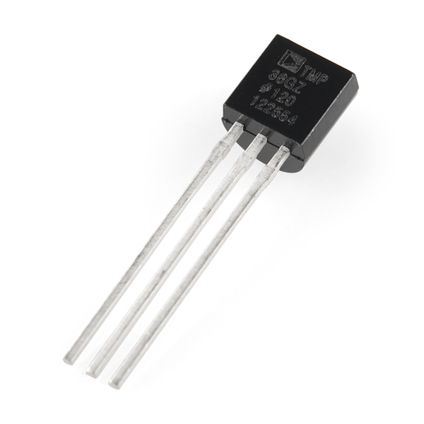
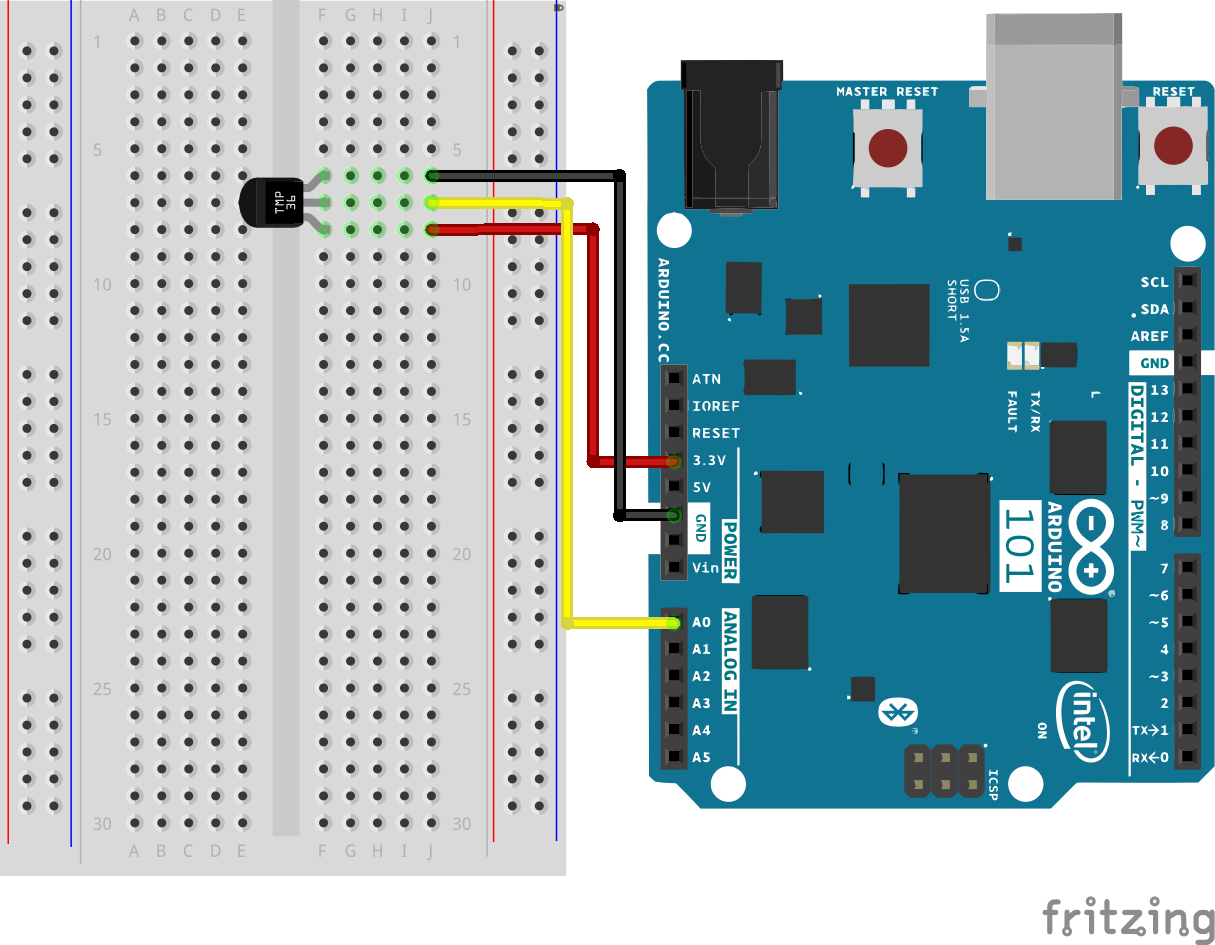
The TMP36 is a low-voltage, precision centigrade temperature sensor. It provides a voltage output that is linearly proportional to the Celsius temperature. It also doesn’t require any external calibration to provide typical accuracies of ±1°C at +25°C and ±2°C over the −40°C to +125°C temperature range. The output voltage can easily convert to temperature using the scale factor of 10 mV/°C.
If you are looking at the flat face with text on it, the center pin is your signal pin; the left-hand pin is supply voltage (3.3V in this tutorial), and the right-hand pin connects to ground.
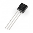
Pro Tip: The TMP36 looks a lot like a transistor. Put a dot of fingernail polish on the top of your TMP36 so it’s easy to find.
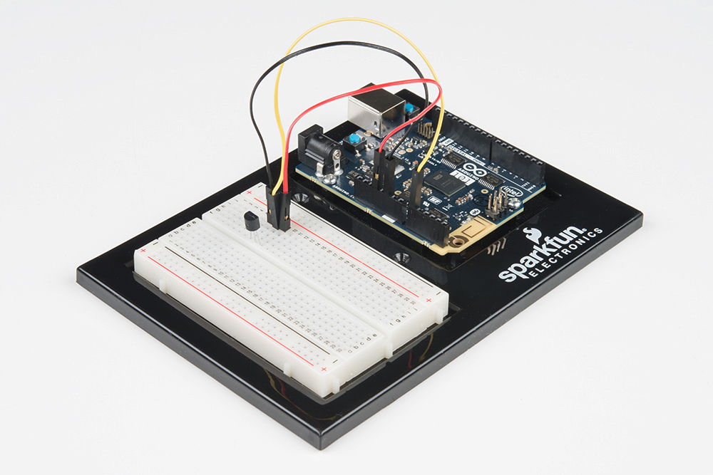
Ready to start hooking everything up? Check out the wiring diagram below to see how everything is connected.
| Polarized Components | Pay special attention to the component’s markings indicating how to place it on the breadboard. Polarized components can only be connected to a circuit in one direction. |
Please note: The temperature sensor can only be connected to a circuit in one direction. See below for the pin outs of the temperature sensor - TMP36.
Open the Arduino IDE software on your computer. Coding in the Arduino language will control your circuit. Open the code for Circuit 9 by accessing the “101 SIK Guide Code” you downloaded and placed into your “Examples” folder earlier.
To open the code go to: File > Examples > 101 SIK Guide Code > Circuit_09
You can also copy and paste the following code into the Arduino IDE. Hit upload, and see what happens!
language:cpp
/*
SparkFun Inventor's Kit
Example sketch 07

TEMPERATURE SENSOR

  Use the "serial monitor" window to read a temperature sensor.

This sketch was written by SparkFun Electronics,
with lots of help from the Arduino community.
This code is completely free for any use.
Visit http://learn.sparkfun.com/products/2 for SIK information.
Visit http://www.arduino.cc to learn more about Arduino.

*/

//analog input pin constant
const int tempPin = 0;

//raw reading variable
int tempVal;

//voltage variable
float volts;

//final temperature variables
float tempC;
float tempF;

void setup()
{
  // start the serial port at 9600 baud
  Serial.begin(9600);
}


void loop()
{
 //read the temp sensor and store it in tempVal
 tempVal = analogRead(tempPin);

 //print out the 10 value from analogRead
 Serial.print("TempVal = ");
 Serial.print(tempVal);

 //print a spacer
 Serial.print(" **** ");

 //converting that reading to voltage by multiplying the reading by 3.3V (voltage of       //the 101 board)
 volts = tempVal * 3.3;
 volts /= 1023.0;

 //print out the raw voltage over the serial port
 Serial.print("volts: ");
 Serial.print(volts, 3);

 //print out divider
 Serial.print(" **** ");

 //calculate temperature celsius from voltage
 //equation found on the sensor spec.
 tempC = (volts - 0.5) * 100 ;

// print the celcius temperature over the serial port
Serial.print(" degrees C: ");
Serial.print(tempC);

//print spacer
 Serial.print(" **** ");

// Convert from celcius to fahrenheit
tempF = (tempC * 9.0 / 5.0) + 32.0;

//print the fahrenheit temperature over the serial port
Serial.print(" degrees F: ");
Serial.println(tempF);

//wait a bit before taking another reading
delay(1000);
}
Serial.begin(9600);
Before using the serial monitor, you must call Serial.begin() to initialize it. 9600 is the "baud rate," or communications speed. When two devices are communicating with each other, both must be set to the same speed.
Serial.print(tempC);
The Serial.print() command is very smart. It can print out almost anything you can throw at it, including variables of all types, quoted text (AKA "strings"), etc. See http://arduino.cc/en/serial/print for more info.
Serial.println(tempF);
Serial.print() will print everything on the same line.
Serial.println() will move to the next line. By using both of these commands together, you can create easy-to-read printouts of text and data.
You should be able to read the temperature your temperature sensor is detecting on the serial monitor in the Arduino IDE. If it isn't working, make sure you have assembled the circuit correctly and verified and uploaded the code to your board, or see the Troubleshooting section.
Example of what you should see in the Arduino IDE’s serial monitor:
TempVal = 223 **** volts: 0.719 **** degrees C: 21.94 **** degrees F: 71.48
TempVal = 224 **** volts: 0.723 **** degrees C: 22.26 **** degrees F: 72.06
TempVal = 224 **** volts: 0.723 **** degrees C: 22.26 **** degrees F: 72.06
TempVal = 224 **** volts: 0.723 **** degrees C: 22.26 **** degrees F: 72.06
TempVal = 224 **** volts: 0.723 **** degrees C: 22.26 **** degrees F: 72.06
TempVal = 224 **** volts: 0.723 **** degrees C: 22.26 **** degrees F: 72.06
TempVal = 223 **** volts: 0.719 **** degrees C: 21.94 **** degrees F: 71.48
TempVal = 223 **** volts: 0.719 **** degrees C: 21.94 **** degrees F: 71.48
This program has no outward indication it is working. To see the results you must open the Arduino IDE's serial monitor (instructions on previous page).
This happens because the serial monitor is receiving data at a different speed than expected. To fix this, click the pull-down box that reads "*** baud" and change it to "9600 baud".
Try pinching the sensor with your fingers to heat it up or pressing a bag of ice against it to cool it down.
You have wired it backward! Unplug your Arduino immediately, let the sensor cool down, and double check your wiring. If you catch it soon enough your sensor may not have been damaged and may still work.
This experiment is your introduction to the servo motor, which is a smart motor that you can tell to rotate to a specific angular location. You will program it to rotate to a series of locations, then sweep across its full range of motion, and then repeat.
You will need the following parts:
If you are conducting this experiment and didn't get the SIK, we suggest using these parts:
You will also need either an Arduino 101 OR Genuino 101 board.
Before continuing with this experiment, we recommend you be familiar with the concepts in the following tutorial:

Unlike the action of most motors that continuously rotate, a servo motor can rotate to and hold a specific angle until it is told to rotate to a different angle. You can control the angle of the servo by sending it a PWM pulse train; the PWM signal is mapped to a specific angle from 0 to 180 degrees.
Inside of the servo there is a gearbox connected to a motor that drives the shaft. There is also a potentiometer that gives feedback on the rotational position of the servo, which is then compared to the incoming PWM signal. The servo adjusts accordingly to match the two signals.
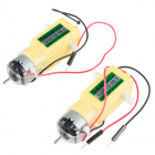
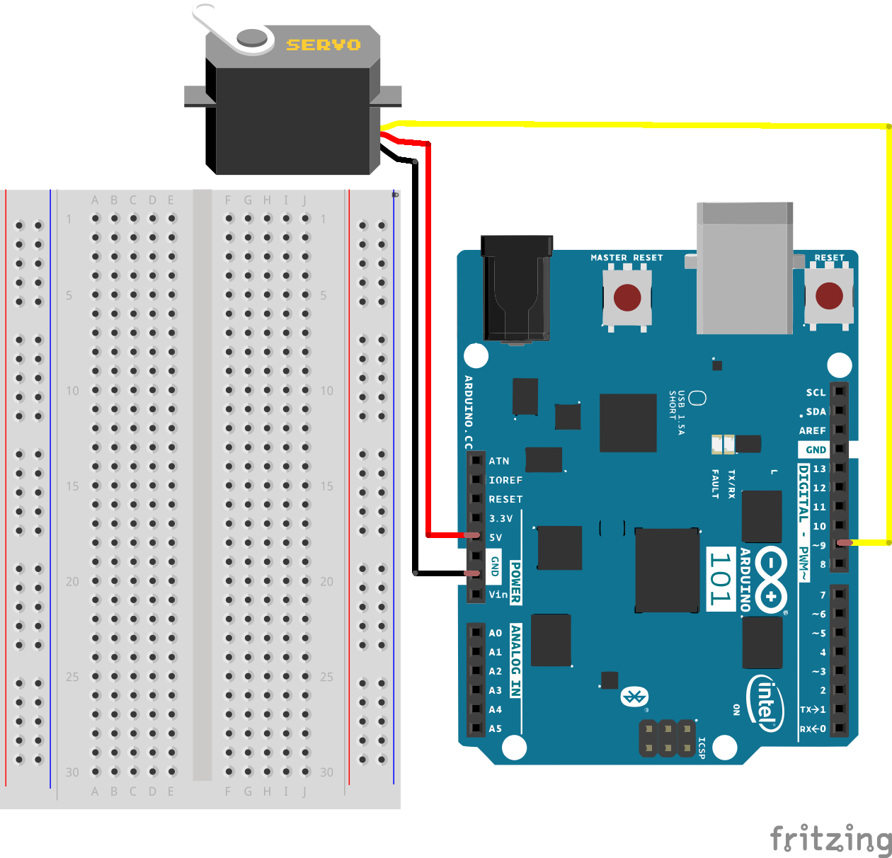
In this experiment, the servo is powered through 5V on the red wire, ground on the black wire, and the white wire is connected to a digital GPIO pin on which you can use PWM (9, 6, 5, 3 on the 101 board).
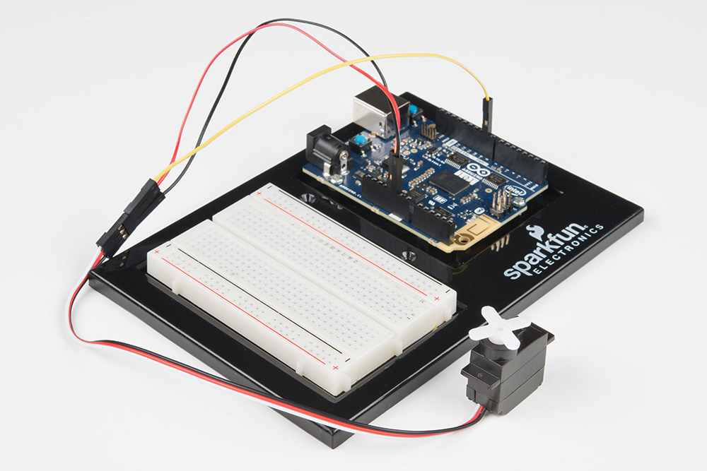
Ready to start hooking everything up? Check out the wiring diagram below to see how everything is connected.
| Polarized Components | Pay special attention to the component’s markings indicating how to place it on the breadboard. Polarized components can only be connected to a circuit in one direction. |
Connect 3x jumper wires to the female 3-pin header on the servo. This will make it easier to breadboard the servo.
Open the Arduino IDE software on your computer. Coding in the Arduino language will control your circuit. Open the code for Circuit 10 by accessing the “101 SIK Guide Code” you downloaded and placed into your “Examples” folder earlier.
To open the code go to: File > Examples > 101 SIK Guide Code > Circuit_10
You can also copy and paste the following code into the Arduino IDE. Hit upload, and see what happens!
language:cpp
/*
SparkFun Inventor's Kit
Example sketch 10

SINGLE SERVO

  Sweep a servo back and forth through its full range of motion.

This sketch was written by SparkFun Electronics,
with lots of help from the Arduino community.
This code is completely free for any use.
Visit http://learn.sparkfun.com/products/2 for SIK information.
Visit http://www.arduino.cc to learn more about Arduino.
*/

//include the servo library
#include <Servo.h>

//create a servo object called servo1
Servo servo1;


void setup()
{
  //attach servo1 to pin 9 on the Arduino 101
  servo1.attach(9);
}


void loop()
{
  //create a local variable to store the servo's position.
  int position;

  // To control a servo, you give it the angle you'd like it
  // to turn to. Servos cannot turn a full 360 degrees, but you
  // can tell it to move anywhere between 0 and 180 degrees.

  // Change position at full speed:

  // Tell servo to go to 90 degrees
  servo1.write(90);

  // Pause to get it time to move
  delay(1000);

  // Tell servo to go to 180 degrees
  servo1.write(180);

  // Pause to get it time to move
  delay(1000);

  // Tell servo to go to 0 degrees
  servo1.write(0);

  // Pause to get it time to move
  delay(1000);


  // Tell servo to go to 180 degrees, stepping by two degrees
  for(position = 0; position < 180; position += 2)
  {
  // Move to next position
    servo1.write(position);
     // Short pause to allow it to move
    delay(20);
  }

  // Tell servo to go to 0 degrees, stepping by one degree
  for(position = 180; position >= 0; position -= 1)
  {
    // Move to next position
    servo1.write(position);
    // Short pause to allow it to move
    delay(20);
  }
}
#include <Servo.h>
#include is a special "preprocessor" command that inserts a library (or any other file) into your sketch. You can type this command yourself, or choose an installed library from the "sketch / import library" menu.
Servo servo1;
When you use a library, you create what is called an object of that library and name it. This object is a Servo library object, and it is named servo1. If you were using multiple servos you would name each one in this way.
servo1.attach(9);
The servo library adds new commands that let you control a servo. To prepare the Arduino to control a servo, you must first create a Servo "object" for each servo (here we've named it "servo1"), and then "attach" it to a digital pin (here we're using pin 9). Think of this as the servo's way of calling a pinMode() function.
servo1.write(180);
The servos in this kit don't spin all the way around, but they can be commanded to move to a specific position. We use the servo library's write() command to move a servo to a specified number of degrees (0 to 180). Remember that the servo requires time to move, so give it a short delay() if necessary.
You should see your servo motor move to various locations at several speeds. If the motor doesn't move, check your connections and make sure you have verified and uploaded the code, or see the Troubleshooting section.
Even with colored wires it is still shockingly easy to plug a servo in backward. This might be the case.
A mistake we made a time or two was simply forgetting to connect the power (red and black wires) to 5 volts and ground (GND).
If the servo begins moving, then twitches, and there's a flashing light on your 101, the power supply you are using is not quite up to the challenge. Using a wall adapter instead of USB should solve this problem.
In the previous experiment, you got to work with a servo motor. Now, we are going to tackle spinning a motor. This requires the use of a transistor, which can switch a larger amount of current than the 101 board can. You will use the transistor to turn a motor on and off -- that's right, a blinking motor!
You will need the following parts:
If you are conducting this experiment and didn't get the SIK, we suggest using these parts:
You will also need either an Arduino 101 OR Genuino 101 board.
Before continuing with this experiment, we recommend you be familiar with the concepts in the following tutorials:
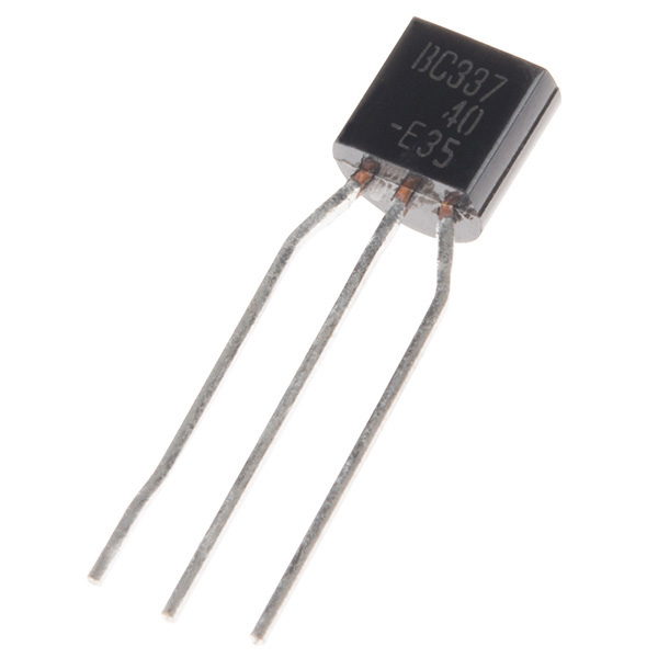
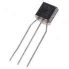
The transistor can be described as a small electronic switch. It allows you to control larger current loads with a smaller current without the risk of burning up sensitive components. A transistor has three pins: a collector, an emitter, and a base. Current can only flow into the transistor in one direction -- through the collector and out the emitter. To control the flow of the current, you apply a small current to the base. This small current can either be digital (on or off) or analog (through using PWM and the analogWrite() function). The larger current will be mirrored from what the smaller current is doing.
Ready to start hooking everything up? Check out the wiring diagram below to see how everything is connected.
| Polarized Components | Pay special attention to the component’s markings indicating how to place it on the breadboard. Polarized components can only be connected to a circuit in one direction. |
Please note: When you’re building the circuit be careful not to mix up the transistor and the temperature sensor; they’re almost identical. Look for “P2N2222A” on the body of the transistor.
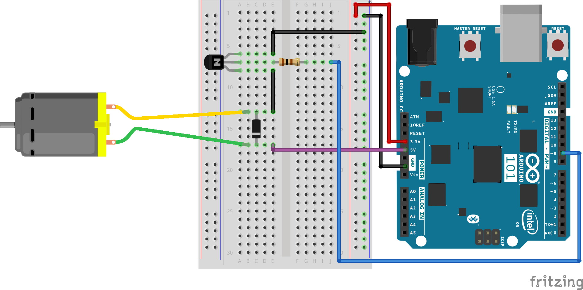
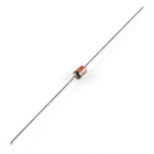
When the spinning motor is suddenly turned off, the magnetic field inside it collapses, generating a voltage spike. This can damage the transistor. To prevent this, we use a "flyback diode," which diverts the voltage spike "around" the transistor. Connect the side of the diode with the band (cathode) to 5V. Connect the other side of the diode (anode) to the black wire on the motor.
Open the Arduino IDE software on your computer. Coding in the Arduino language will control your circuit. Open the code for Circuit 11 by accessing the “101 SIK Guide Code” you downloaded and placed into your “Examples” folder earlier.
To open the code go to: File > Examples >101 SIK Guide Code > Circuit_11
You can also copy and paste the following code into the Arduino IDE. Hit upload, and see what happens!
language:cpp
/*
SparkFun Inventor's Kit
Example sketch 11

SPINNING A MOTOR

  Use a transistor to spin a motor at different speeds.

This sketch was written by SparkFun Electronics,
with lots of help from the Arduino community.
This code is completely free for any use.
Visit http://learn.sparkfun.com/products/2 for SIK information.
Visit http://www.arduino.cc to learn more about Arduino.
*/

// constant pin for the transistor connected to the motor
const int motorPin = 9;


void setup()
{
  //set motorPin as OUTPUT
  pinMode(motorPin, OUTPUT);
}


void loop()
{
  // Here we've used comments to disable some of the examples.
  // To try different things, uncomment one of the following lines
  // and comment the other ones. See the functions below to learn
  // what they do and how they work.

   motorOnThenOff();
  // motorOnThenOffWithSpeed();
  // motorAcceleration();
}


// This function turns the motor on and off like the blinking LED.
// Try different values to affect the timing.
void motorOnThenOff()
{
  // milliseconds to turn the motor on
  int onTime = 3000;
  // milliseconds to turn the motor off
  int offTime = 3000;

  // turn the motor on (full speed)
  digitalWrite(motorPin, HIGH);
  // delay for onTime milliseconds
  delay(onTime);
  // turn the motor off
  digitalWrite(motorPin, LOW);
  // delay for offTime milliseconds
  delay(offTime);
}


// This function alternates between two speeds.
// Try different values to affect the timing and speed.
void motorOnThenOffWithSpeed()
{
  // between 0 (stopped) and 255 (full speed)
  int Speed1 = 200;
   // milliseconds for speed 1
  int Time1 = 3000;

  // between 0 (stopped) and 255 (full speed)
  int Speed2 = 50;
  // milliseconds to turn the motor off
  int Time2 = 3000;

  // turns the motor On
  analogWrite(motorPin, Speed1);
  // delay for onTime milliseconds
  delay(Time1);
  // turns the motor Off
  analogWrite(motorPin, Speed2);
  // delay for offTime milliseconds
  delay(Time2);
}


// This function slowly accelerates the motor to full speed,
// then back down to zero.
void motorAcceleration()
{
  // milliseconds between each speed step
  int speed;
  int delayTime = 20;

  // accelerate the motor
  for(speed = 0; speed <= 255; speed++)
  {
    // set the new speed
    analogWrite(motorPin,speed);
    // delay between speed steps
    delay(delayTime);
  }

  // decelerate the motor
  for(speed = 255; speed >= 0; speed--)
  {
    // set the new speed
    analogWrite(motorPin,speed);
    // delay between speed steps
    delay(delayTime);
  }
}
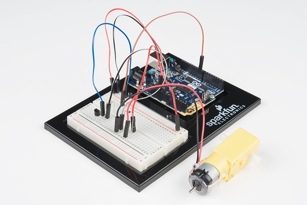
The DC Motor should spin if you have assembled the circuit’s components correctly, and also verified/uploaded the correct code. If your circuit is not working, check the Troubleshooting section.
If you sourced your own transistor, double check with the data sheet that the pinout is compatible with the transistor you are using (many are reversed).
If you sourced your own motor, double check that it will work with 5 volts and that it does not draw too much power.
Sometimes the Arduino will disconnect from the computer. Try unplugging and then replugging it into your USB port.
In the previous experiment you controlled a motor. But, it only spun in one direction. How could you make it spin in both directions? With the SparkFun Motor Driver! In this experiment you will use the motor driver to control the motor's direction and speed.
You will need the following parts:
If you are conducting this experiment and didn't get the SIK, we suggest using these parts:
You will also need either an Arduino 101 OR Genuino 101 board.

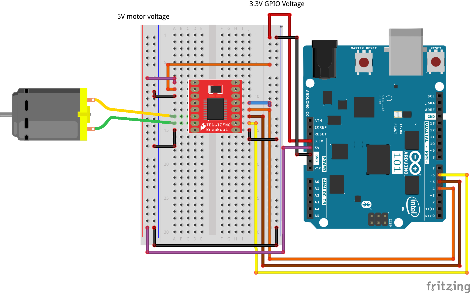
The SparkFun Motor Driver is a small circuit board that has all of the circuitry on it to make controlling motors easier. At the heart of the driver board is an H-Bridge, which allows you to control both the direction and the amount of an electrical current. You can think of it as a smart transistor that allows you to change the direction of the current.
To switch the direction of the current, you use two pins to toggle pins on the board either HIGH or LOW. If the two direction pins are both HIGH or LOW at the same time, that causes the board to brake the motors. If one pin is HIGH and the other is LOW, the motor spins in one direction. If you flip-flop the states, the motor spins in the opposite direction. This board also has a power-saving mode that uses a standby pin. To use the driver board, you pull the standby pin HIGH. If you are not using the board and want to conserve power, you can push the pin LOW, and the motors won’t run.
You can control up to two motors with a single driver board. The pin names are printed on the bottom of the controller board.
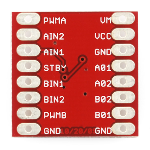
| PWMA | PWM signal for controlling the speed of motor A |
| AIN2 | Direction pin 2 for motor A |
| AIN1 | Direction pin 1 for motor A |
| STBY | Standby HIGH for board on, LOW for board off |
| BIN1 | Direction pin for motor B |
| BIN2 | Direction pin 2 for motor B |
| PWMB | PWM signal for controlling the speed of motor B |
| GND | Ground |
| VM | Motor power source 5V to 14V |
| VCC | Chip voltage (3.3V) |
| GND | Ground |
| A01 | Motor A connection |
| A02 | Motor A connection |
| B02 | Motor B Connection |
| B01 | Motor B Connection |
| GND | Ground |
Note: All ground pins need to be connected to ground, and the STBY pin cannot be floating, or not connected to ground or 3.3V. In this experiment, we hardwired it to 3.3V.
Ready to start hooking everything up? Check out the wiring diagram below to see how everything is connected.
| Polarized Components | Pay special attention to the component’s markings indicating how to place it on the breadboard. Polarized components can only be connected to a circuit in one direction. |
**Note: We hardwire or connect the standby pin directly to 3.3V. If you want to be able to enable/disable the motor controller in its entirety, you can connect it to a digital GPIO pin and toggle it using a digitalWrite(). **
Open the Arduino IDE software on your computer. Coding in the Arduino language will control your circuit. Open the code for Circuit 12 by accessing the “101 SIK Guide Code” you downloaded and placed into your “Examples” folder earlier.
To open the code go to: File > Examples > 101 SIK Guide Code > Circuit_12
You can also copy and paste the following code into the Arduino IDE. Hit upload, and see what happens!
language:cpp
/*
SparkFun Inventor's Kit for Arduino
Example sketch 12

SparkFun Motor Driver

Use the SparkFun Motor Driver to control the speed and direction of a motor

This sketch was written by SparkFun Electronics,
with lots of help from the Arduino community.
This code is completely free for any use.
Visit http://learn.sparkfun.com/products/2 for SIK information.
Visit http://www.arduino.cc to learn more about Arduino.
*/

//define the two direction logic pins and the speed / PWM pin
const int DIR_A = 5;
const int DIR_B = 4;
const int PWM = 6;

void setup()
{
//set all pins as output
pinMode(DIR_A, OUTPUT);
pinMode(DIR_B, OUTPUT);
pinMode(PWM, OUTPUT);
}

void loop()
{
 //drive forward at full speed by pulling DIR_A High
 //and DIR_B low, while writing a full 255 to PWM to
 //control speed
 digitalWrite(DIR_A, HIGH);
 digitalWrite(DIR_B, LOW);
 analogWrite(PWM, 255);

 //wait 1 second
 delay(1000);

 //Brake the motor by pulling both direction pins to
 //the same state (in this case LOW). PWM doesn't matter
 //in a brake situation, but set as 0.
 digitalWrite(DIR_A, LOW);
 digitalWrite(DIR_B, LOW);
 analogWrite(PWM, 0);

 //wait 1 second
 delay(1000);

 //change direction to reverse by flipping the states
 //of the direction pins from their forward state
 digitalWrite(DIR_A, LOW);
 digitalWrite(DIR_B, HIGH);
 analogWrite(PWM, 150);

 //wait 1 second
 delay(1000);

 //Brake again
 digitalWrite(DIR_A, LOW);
 digitalWrite(DIR_B, LOW);
 analogWrite(PWM, 0);

 //wait 1 second
 delay(1000);
 }
 language:cpp
 digitalWrite(DIR_A, HIGH);
 digitalWrite(DIR_B, LOW);
 analogWrite(PWM, 255);
The Motor Driver uses a control logic that works by pulling certain pins HIGH or LOW (pins 4 and 5 in this case) to change the direction of the motor's rotation and then send a PWM signal to pin 6 to control the speed. This chunk of code runs to motor in one direction at full speed.
language:cpp
digitalWrite(DIR_A, LOW);
digitalWrite(DIR_B, HIGH);
analogWrite(PWM, 150);
This chunk of code is similar, but changes the direction by flipping the direction pin's state and setting the PWM pin at a slower speed.
language:cpp
digitalWrite(DIR_A, LOW);
digitalWrite(DIR_B, LOW);
analogWrite(PWM, 0);
This final chunk of code demonstrates the logic for stopping or "braking" the motor by pulling both direction pins to the same state. In this case we used LOW, but both set to HIGH would produce the same results. In a brake, the PWM level doesn't matter. We set it to 0 as more of a formality than anything. If not, see the Troubleshooting section below.
You should see the motor spin in one direction at full speed for a second, then brake for a second, reverse direction and run at 150 PWM speed for a second, brake, and then repeat.

Make sure that you have the enable pin as well as the logic and PWM pins wired correctly. It's easy to make a wiring error, as the names of the pins of the board are on the bottom.
Double check that you have wired the standby pin to 3.3V! Without it, the IC is in standby mode.
Double check your code. You may not have inverted the logic pin's state to reverse the motor.
In Experiment 12 you used the Motor Driver board to control a motor's direction and speed. The issue is that you had to hard code the direction and speed of your motor. Most applications that make use of a motor allow the user to control the speed and direction of the motor, much as you would your own car. In this experiment we will add two inputs and use them to control the direction and speed of your motor.
Are you ready to get your motor running? Let's go!
You will need the following parts:
If you are conducting this experiment and didn't get the SIK, we suggest using these parts:
You will also need either an Arduino 101 OR Genuino 101 board.
Ready to start hooking everything up? Check out the wiring diagram below to see how everything is connected.
| Polarized Components | Pay special attention to the component’s markings indicating how to place it on the breadboard. Polarized components can only be connected to a circuit in one direction. |

Open the Arduino IDE software on your computer. Coding in the Arduino language will control your circuit. Open the code for Circuit 13 by accessing the “SIK Guide Code” you downloaded and placed into your “Examples” folder earlier.
To open the code go to: File > Examples > SIK Guide Code > Circuit_13
You can also copy and paste the following code into the Arduino IDE. Hit upload, and see what happens!
language:cpp
/*
SparkFun Inventor's Kit
Example sketch 13

SparkFun Motor Controller with Inputs

  Use the inputs to manually set the direction and speed of a motor.


This sketch was written by SparkFun Electronics,
with lots of help from the Arduino community.
This code is completely free for any use.
Visit http://learn.sparkfun.com/products/2 for SIK information.
Visit http://www.arduino.cc to learn more about Arduino.
*/
 //define the two direction logic pins and the speed / PWM pin
 const int DIR_A = 5;
 const int DIR_B = 4;
 const int PWM = 6;

 //define the input pins
 const int switchPin = 10;
 const int potPin = 0;

 void setup()
 {
  //set all pins as output
  pinMode(DIR_A, OUTPUT);
  pinMode(DIR_B, OUTPUT);
  pinMode(PWM, OUTPUT);
  //set the switchPin as INPUT
  pinMode(switchPin, INPUT);
  }

void loop()
{
//read the value from the potentiometer and divide
//it by 4 to get a 0-255 range. Store the value in
//the speed variable
int speed = analogRead(potPin) / 4;

 //read the value of the switch and store it in the
 //direction variable.


//if the value of direction is HIGH drive forward at
//a speed set by the speed variable, else drive reverse
//at a speed set by the speed variable.
if (digitalRead(switchPin) == HIGH)
{
  forward(speed);
}
else
 {
 reverse(speed);
 }
}

//create a custom function that defines moving forward
//the forward() function accepts one parameter and that is
//the speed at which you want to drive forward (0-255)
 void forward(int spd)
 {
 //motor contoller direction pins set to forward
 digitalWrite(DIR_A, HIGH);
 digitalWrite(DIR_B, LOW);

  //write the speed by using the parameter of spd
 analogWrite(PWM, spd);
  }

//create a custom function that defines moving in reverse
//the reverse() function accepts one parameter and that is
//the speed at which you want to drive in reverse (0-255)
void reverse(int spd)
{
//set motor controller pins to reverse
digitalWrite(DIR_A, LOW);
digitalWrite(DIR_B, HIGH);

 //write the speed by using the parameter of spd
 analogWrite(PWM, spd);
 }
These big, scary functions take a single value as a parameter: speed. Each function then accepts that value and applies it to the analogWrite() function inside of the custom function. Custom functions are a great way to clean up your code and also make it more modular and useful in other applications. Watch out! You are halfway to writing your own library.
You should be able to control the motor's direction by flipping the SPDT switch and then the speed through the potentiometer. Go ahead and play with both inputs to make sure they both work and the motor is responding to those inputs.

Double check the wiring of your switch, but also double check your if() statement to make sure there isn't a semicolon after the statement.
Also, double check to make sure that you have the standby pin wired correctly (to 3.3V).
In this experiment, we will again bridge the gap between the digital world and the analog world. We'll be using a piezo buzzer that makes a small "click" when you apply voltage to it (try it!). By itself that isn't terribly exciting, but if you turn the voltage on and off hundreds of times a second, the piezo buzzer will produce a tone. And if you string a bunch of tones together, you've got music! This circuit and sketch will play a classic tune. We'll never let you down!
We have also added a button in series with the buzzer. Why? Because every good noise maker needs a mute button! To hear the song being played from your 101 board using the buzzer you need to press and hold the button down. To mute the buzzer, just release the button.
You will need the following parts:
If you are conducting this experiment and didn't get the SIK, we suggest using these parts:
You will also need either an Arduino 101 OR Genuino 101 board.

The buzzer is a small component with a piece of metal in it that moves when you apply a voltage across it. This motion causes a small sound, or "click." If you turn the voltage on and off fast enough, you get different beeps, squeals, chirps and buzzes. You will use PWM to control the speed of turning the piezo on and off -- and, in turn, the audio frequency coming out of the buzzer. Adjusting the PWM enables you to get legitimate notes out of the buzzer.
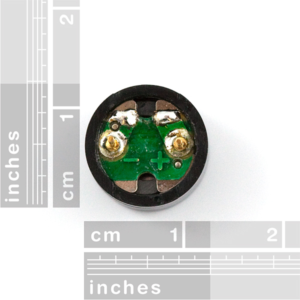
If you flip the buzzer over and look at the bottom, you will see that one pin has a (+) next to it. That pin gets connected to a signal from a PWM pin. The other pin should be connected to ground.
Ready to start hooking everything up? Check out the wiring diagram below to see how everything is connected.
| Polarized Components | Pay special attention to the component’s markings indicating how to place it on the breadboard. Polarized components can only be connected to a circuit in one direction. |
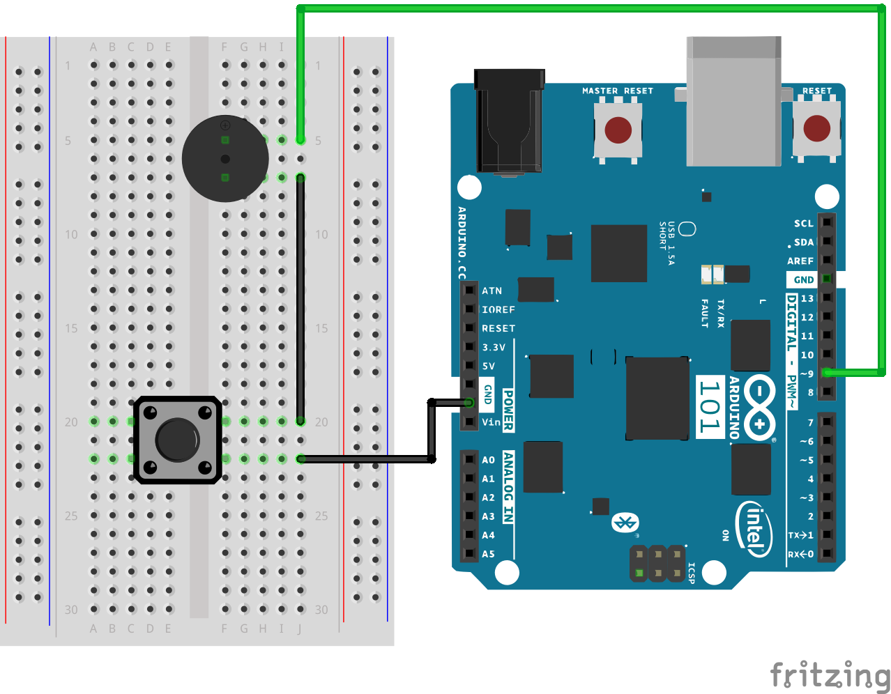
Open the Arduino IDE software on your computer. Coding in the Arduino language will control your circuit. Open the code for Circuit 14 by accessing the “101 SIK Guide Code” you downloaded and placed into your “Examples” folder earlier.
To open the code go to: File > Examples > SIK Guide Code > Circuit_14
You can also copy and paste the following code into the Arduino IDE. Hit upload, and see what happens!
language:cpp
/*
SparkFun Inventor's Kit
Example sketch 14

BUZZER

  Use the buzzer to play a song!

This sketch was written by SparkFun Electronics,
with lots of help from the Arduino community.
(This sketch was originally developed by D. Cuartielles for K3)
This code is completely free for any use.
Visit http://learn.sparkfun.com/products/2 for SIK information.
Visit http://www.arduino.cc to learn more about Arduino.

*/

/*
This sketch uses the buzzer to play songs.
The Arduino's tone() command will play notes of a given frequency.
We'll provide a function that takes in note characters (a-g),
and returns the corresponding frequency from this table:

  note  frequency
  c     262 Hz
  d     294 Hz
  e     330 Hz
  f     349 Hz
  g     392 Hz
  a     440 Hz
  b     494 Hz
  C     523 Hz

For more information, see http://arduino.cc/en/Tutorial/Tone
*/

const int buzzerPin = 9;

// We'll set up an array with the notes we want to play
// change these values to make different songs!

// Length must equal the total number of notes and spaces

const int songLength = 18;

// Notes is an array of text characters corresponding to the notes
// in your song. A space represents a rest (no tone)

char notes[] = "cdfda ag cdfdg gf "; // a space represents a rest

// Beats is an array of values for each note and rest.
// A "1" represents a quarter-note, 2 a half-note, etc.
// Don't forget that the rests (spaces) need a length as well.

int beats[] = {1,1,1,1,1,1,4,4,2,1,1,1,1,1,1,4,4,2};

// The tempo is how fast to play the song.
// To make the song play faster, decrease this value.

int tempo = 150;


void setup()
{
  pinMode(buzzerPin, OUTPUT);
}


void loop()
{
  int i, duration;

  for (i = 0; i < songLength; i++) // step through the song arrays
  {
    duration = beats[i] * tempo;  // length of note/rest in ms

    if (notes[i] == ' ')          // is this a rest?
    {
      delay(duration);            // then pause for a moment
    }
    else                          // otherwise, play the note
    {
      tone(buzzerPin, frequency(notes[i]), duration);
      delay(duration);            // wait for tone to finish
    }
    delay(tempo/10);              // brief pause between notes
  }

  // We only want to play the song once, so we'll pause forever:
  while(true){}
  // If you'd like your song to play over and over,
  // remove the above statement
}


int frequency(char note)
{
  // This function takes a note character (a-g), and returns the
  // corresponding frequency in Hz for the tone() function.

  int i;
  const int numNotes = 8;  // number of notes we're storing

  // The following arrays hold the note characters and their
  // corresponding frequencies. The last "C" note is uppercase
  // to separate it from the first lowercase "c". If you want to
  // add more notes, you'll need to use unique characters.

  // For the "char" (character) type, we put single characters
  // in single quotes.

  char names[] = { 'c', 'd', 'e', 'f', 'g', 'a', 'b', 'C' };
  int frequencies[] = {262, 294, 330, 349, 392, 440, 494, 523};

  // Now we'll search through the letters in the array, and if
  // we find it, we'll return the frequency for that note.

  for (i = 0; i < numNotes; i++)  // Step through the notes
  {
    if (names[i] == note)         // Is this the one?
    {
      return(frequencies[i]);     // Yes! Return the frequency
    }
  }
  return(0);  // We looked through everything and didn't find it,
              // but we still need to return a value, so return 0.
}
char notes[] = "cdfda ag cdfdg gf ";
char names[] = {'c','d','e','f','g','a','b','C'};
Up until now we've been working solely with numerical data, but the Arduino can also work with text. Characters (single, printable, letters, numbers and other symbols) have their own type, called "char." When you have an array of characters, it can be defined between double-quotes (also called a "string"), OR as a list of single-quoted characters.
tone(pin, frequency, duration);
One of Arduino's many useful built-in commands is the tone() function. This function drives an output pin at a certain frequency, making it perfect for driving buzzers and speakers. If you give it a duration (in milliseconds), it will play the tone, then stop. If you don't give it a duration, it will keep playing the tone forever (but you can stop it with another function, noTone() ).
What you should see -- well, nothing! What you should hear -- well, nothing to start with! But you should be able to hear a song if you press and hold the button down as soon as the sketch finishes the upload. If you catch the song halfway through or you feel as though it isn't playing, press the reset button and hold down the press button.
If it isn't working, make sure you have assembled the circuit correctly and verified and uploaded the code to your board, or see the Troubleshooting section.
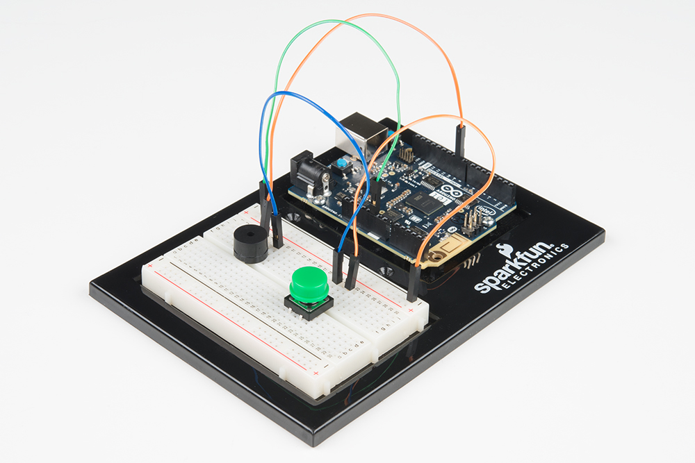
Given the size and shape of the piezo buzzer it is easy to miss the right holes on the breadboard. Try double checking its placement.
Also, double check to make sure the push button is wired correctly. If you miswired it, then the circuit will never be completed whether you press the button or not.
You may only catch part of the song by the time you press and hold the button. To start the song over again press the MASTER RESET button on the 101 board while holding the mute button down.
The code is written so you can easily add your own songs. Go forth and rock on!
You have used a couple of different analog inputs in previous experiments. In this experiment you will look at sound as an input and use the SparkFun Sound Detector Board. You will use the Envelope output on the board to measure how loud it is in the room, and then use some snazzy code called a switch case to change the color and RGB accordingly.
We call this the fun-o-meter! If things get out of control, you'll see red!
You will need the following parts:
If you are conducting this experiment and didn't get the SIK, we suggest using these parts:
You will also need either an Arduino 101 OR Genuino 101 board.
Before continuing with this experiment, we recommend you be familiar with the concepts in the following tutorials:

The Sound Detector Board is a nifty little sensor! It is a microphone circuit that saves you quite a bit of wiring. Once you attach the board to power (3.3V) on the VCC pin and ground to GND pin, there are three options for different signals to use as inputs for the 101.
The first signal, GATE, is a digital signal that turns on when the ambient sound passes a certain threshold. GATE also has an LED wired to it on the Sound Detector. Once you power it up correctly and make noise, you will see the red LED light up when it is "loud" and turn off when it is "quiet."
The second signal, ENVELOPE, scales the amplitude (how loud it is) to a 0-1023 10-bit value. In a quiet living room this level registers at about 10.
The final signal is the raw AUDIO signal. In a quiet room, the signal levels out around 512 and will produce a waveform curve based on the frequency of the ambient sound. The raw AUDIO signal would be something to use if you were looking to do some audio processing that is beyond the scope of this guide. To learn more about the specifics of the Sound Detector Board, please check out our hookup guide for it.
Ready to start hooking everything up? Check out the wiring diagram below to see how everything is connected.
| Polarized Components | Pay special attention to the component’s markings indicating how to place it on the breadboard. Polarized components can only be connected to a circuit in one direction. |
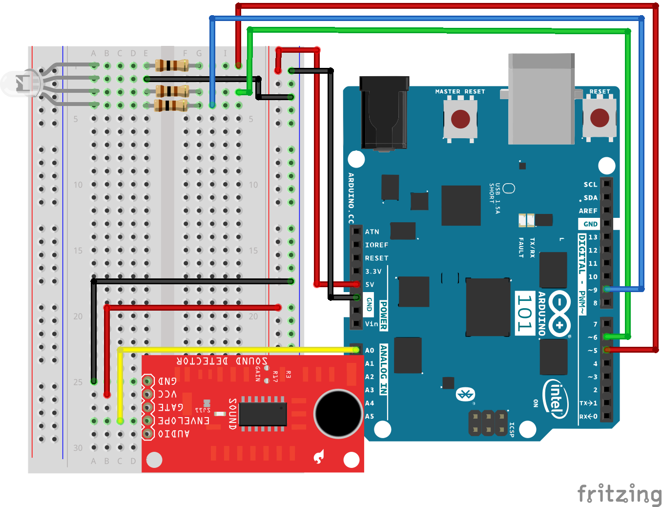
Open the Arduino IDE software on your computer. Coding in the Arduino language will control your circuit. Open the code for Circuit 15 by accessing the “101 SIK Guide Code” you downloaded and placed into your “Examples” folder earlier.
To open the code go to: File > Examples >101 SIK Guide Code > Circuit_15
You can also copy and paste the following code into the Arduino IDE. Hit upload, and see what happens!
language:cpp
/*
SparkFun Inventor's Kit
Example sketch 15

SOUND DETECTOR

Use the sound detector to measure the volume of the surrounding area and change the
color of an RGB based on that volume.

 //pin variables
const int redPin = 5;
const int greenPin = 6;
const int bluePin = 9;
const int soundPin = 0;

//variables for storing raw sound and scaled value
int sound;
int scale;

void setup()
{
 //start the serial port a@ 9600bps
 Serial.begin(9600);
 //set RGB pins to OUTPUT
 pinMode(redPin, OUTPUT);
 pinMode(greenPin, OUTPUT);
 pinMode(bluePin, OUTPUT);
}

void loop()
{
 //read and store the audio from Envelope pin
 sound = analogRead(soundPin);
 //map sound which in a quiet room a clap is 300
 //from 0 to 3 to be used with switch case
 scale = map(sound, 0, 300, 0, 3);

 //print values over the serial port for debugging
 Serial.print(sound);
 Serial.print("   ");
 Serial.println(scale);

 //switch case on scaled value
switch (scale)
{
//if 0 RGB = Blue
case 0:
  digitalWrite(redPin, LOW);
  digitalWrite(greenPin, LOW);
  digitalWrite(bluePin, HIGH);
  break;
//if 1 RGB = Green
case 1:
  digitalWrite(redPin, LOW);
  digitalWrite(greenPin, HIGH);
  digitalWrite(bluePin, LOW);
  break;
//if 2 RGB = Yellow
case 2:
  digitalWrite(redPin, HIGH);
  digitalWrite(greenPin, HIGH);
  digitalWrite(bluePin, LOW);
  break;
//if 3 RGB = Red
case 3:
  digitalWrite(redPin, HIGH);
  digitalWrite(greenPin, LOW);
  digitalWrite(bluePin, LOW);
  break;
//default off
default:
  digitalWrite(redPin, LOW);
  digitalWrite(greenPin, LOW);
  digitalWrite(bluePin, LOW);
  break;
 }
}
scale = map(sound,0,300,0,3
This may seem like an odd mapping of values. This is a setup for using the switch case, and we need to map a large set of values down to three to four choices. The map function works both ways, but it comes in most handy to build ranges of values paired with a switch case.
switch(value)
{
 case(0):
 //do something
 break;
 case(1):
 //do something else
 break;
 default:
 //do another thing
 break;
}
Switch case comes in really handy when you think you are going to need a really long chain of if else() statements where you are trying to do something based on a range of values. Switch() looks at a variable and then looks for its match within a list of cases. If the match is not available it uses a default setting. Each case also has its own break command, which allows Arduino to escape out of the switch case and continue on its way.
Once the code is uploaded and the sketch starts, the RGB should turn blue. Make a lot of noise, and the RGB should change from blue to green and then to yellow ... if you get really loud it may turn red! Don't worry; we won't call the cops!
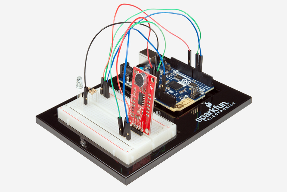
Open up your serial monitor to do some debugging. Check your quiet value and then make a bunch of noise. Adjust your map function to make sure your range is the same.
Make sure you have the sound detector board hooked up to 3.3V and you are reading the Envelope pin.
Sometimes the Arduino 101 board will disconnect from the computer. Try unplugging and then replugging it into your USB port.
Now we are going to step into the world of raw ICs (integrated circuits). In this experiment, you’ll learn all about using a shift register. The shift register will give your 101 board an additional eight outputs, using only three pins on your board. For this experiment, you’ll practice by using the shift register to control eight LEDs. That's right -- two more LEDs than Experiment 4!
You will need the following parts:
If you are conducting this experiment and didn't get the SIK, we suggest using these parts:
You will also need either an Arduino 101 OR Genuino 101 board.
Before continuing with this experiment, we recommend you be familiar with the concepts in the following tutorials:
The shift register is an Integrated Circuit (IC). ICs are tiny, plastic-sealed packages of popular and often used circuits. ICs act as single components that perform a specific job function and simplify what used to be time- and space-consuming circuit design.
The shift register, in essence, allows you to control up to eight outputs while only using three pins on your 101 board. It enables you to control more outputs with fewer pins compared to Experiment 4, where you used six pins for six individual outputs.
Think of it this way: the data going into the shift register is like a train of eight different train cars. If a car is full of cargo, the data it represents is a 1. If the train car is empty, the data it represents is a 0. When the whole train has entered the shift register, it gets broken up, and each car gets placed on its own track. These tracks can be translated to the eight output pins of the shift register. If the car is full (1) the pin that it is on is pulled HIGH; if the car is empty (0) the pin is pulled LOW. If you constantly send train after train into the shift register, you can animate LEDs or control something like a 7-segment display to count down or even a whole lot of motors turning at different times. All of this happens just by sending the shift register trains with different patterns of 1s and 0s.
To learn more about trains shift registers, check out our Shift Register Tutorial.
Ready to start hooking everything up? Check out the wiring diagram below to see how everything is connected.
| Polarized Components | Pay special attention to the component’s markings indicating how to place it on the breadboard. Polarized components can only be connected to a circuit in one direction. |
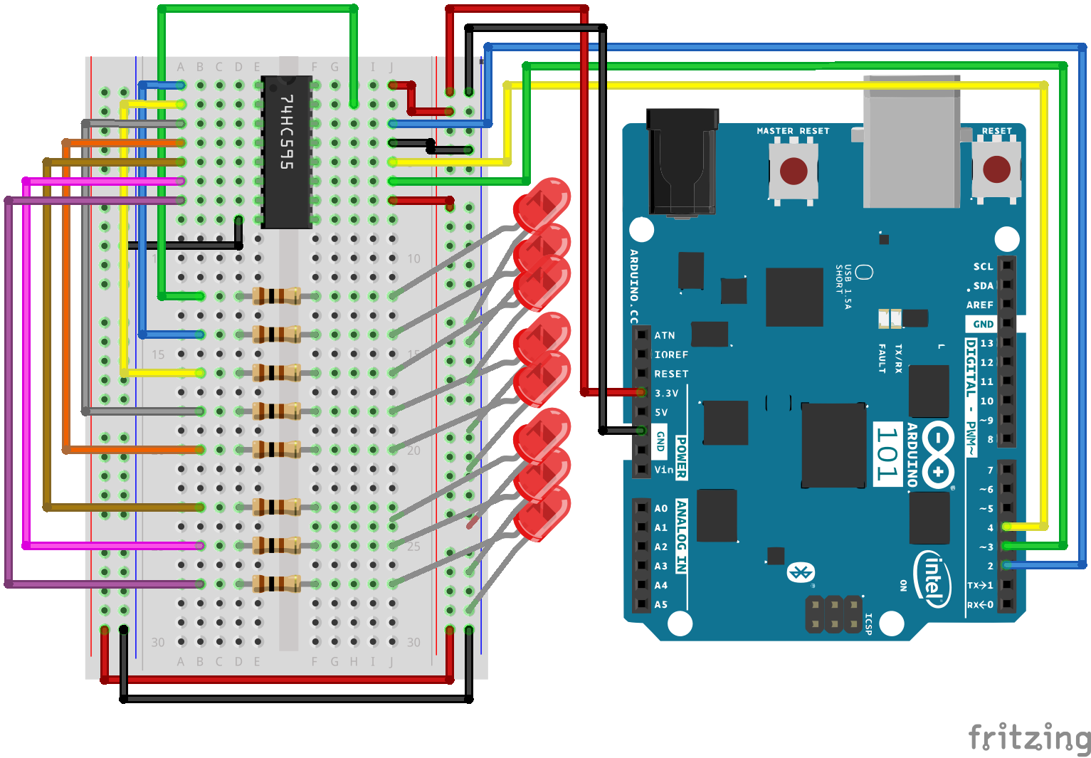
Open the Arduino IDE software on your computer. Coding in the Arduino language will control your circuit. Open the code for Circuit 16 by accessing the “101 SIK Guide Code” you downloaded and placed into your “Examples” folder earlier.
To open the code go to: File > Examples >101 SIK Guide Code > Circuit_16
You can also copy and paste the following code into the Arduino IDE. Hit upload, and see what happens!
language:cpp
/*
SparkFun Inventor's Kit
Example sketch 16

SHIFT REGISTER

  Use a shift register to turn three pins into eight (or more!)
  outputs

This sketch was written by SparkFun Electronics,
with lots of help from the Arduino community.
This code is completely free for any use.
Visit http://learn.sparkfun.com/products/2 for SIK information.
Visit http://www.arduino.cc to learn more about Arduino.
*/


// Pin definitions:
// The 74HC595 uses a type of serial connection called SPI
// (Serial Peripheral Interface) that requires three pins:

int datapin = 2;
int clockpin = 3;
int latchpin = 4;

// We'll also declare a global variable for the data we're
// sending to the shift register:

byte data = 0;


void setup()
{
  // Set the three SPI pins to be outputs:

  pinMode(datapin, OUTPUT);
  pinMode(clockpin, OUTPUT);
  pinMode(latchpin, OUTPUT);
}


void loop()
{
  // We're going to use the same functions we played with back
  // in circuit 04, "Multiple LEDs," we've just replaced
  // digitalWrite() with a new function called shiftWrite()
  // (see below). We also have a new function that demonstrates
  // binary counting.

  // To try the different functions below, uncomment the one
  // you want to run, and comment out the remaining ones to
  // disable them from running.

  oneAfterAnother();      // All on, all off

  //oneOnAtATime();       // Scroll down the line

  //pingPong();           // Like above, but back and forth

  //randomLED();          // Blink random LEDs

  //marquee();

  //binaryCount();        // Bit patterns from 0 to 255
}


void shiftWrite(int desiredPin, boolean desiredState)

// This function lets you make the shift register outputs
// HIGH or LOW in exactly the same way that you use digitalWrite().

// Like digitalWrite(), this function takes two parameters:

//    "desiredPin" is the shift register output pin
//    you want to affect (0-7)

//    "desiredState" is whether you want that output
//    to be HIGH or LOW

// Inside the Arduino, numbers are stored as arrays of "bits,"
// each of which is a single 1 or 0 value. Because a "byte" type
// is also eight bits, we'll use a byte (which we named "data"
// at the top of this sketch) to send data to the shift register.
// If a bit in the byte is "1," the output will be HIGH. If the bit
// is "0," the output will be LOW.

// To turn the individual bits in "data" on and off, we'll use
// a new Arduino commands called bitWrite(), which can make
// individual bits in a number 1 or 0.
{
  // First we'll alter the global variable "data," changing the
  // desired bit to 1 or 0:

  bitWrite(data,desiredPin,desiredState);

  // Now we'll actually send that data to the shift register.
  // The shiftOut() function does all the hard work of
  // manipulating the data and clock pins to move the data
  // into the shift register:

  shiftOut(datapin, clockpin, MSBFIRST, data);

  // Once the data is in the shift register, we still need to
  // make it appear at the outputs. We'll toggle the state of
  // the latchPin, which will signal the shift register to "latch"
  // the data to the outputs. (Latch activates on the high-to
  // -low transition).

  digitalWrite(latchpin, HIGH);
  digitalWrite(latchpin, LOW);
}


/*
oneAfterAnother()

This function will light one LED, delay for delayTime, then light
the next LED, and repeat until all the LEDs are on. It will then
turn them off in the reverse order.
*/

void oneAfterAnother()
{
  int index;
  int delayTime = 100; // Time (milliseconds) to pause between LEDs
                       // Make this smaller for faster switching

  // Turn all the LEDs on:

  // This for() loop will step index from 0 to 7
  // (putting "++" after a variable means add one to it)
  // and will then use digitalWrite() to turn that LED on.

  for(index = 0; index <= 7; index++)
  {
    shiftWrite(index, HIGH);
    delay(delayTime);
  }

  // Turn all the LEDs off:

  // This for() loop will step index from 7 to 0
  // (putting "--" after a variable means subtract one from it)
  // and will then use digitalWrite() to turn that LED off.

  for(index = 7; index >= 0; index--)
  {
    shiftWrite(index, LOW);
    delay(delayTime);
  }
}


/*
oneOnAtATime()

This function will step through the LEDs, lighting one at at time.
*/

void oneOnAtATime()
{
  int index;
  int delayTime = 100; // Time (milliseconds) to pause between LEDs
                       // Make this smaller for faster switching

  // step through the LEDs, from 0 to 7

  for(index = 0; index <= 7; index++)
  {
    shiftWrite(index, HIGH);    // turn LED on
    delay(delayTime);       // pause to slow down the sequence
    shiftWrite(index, LOW); // turn LED off
  }
}


/*
pingPong()

This function will step through the LEDs, lighting one at at time,
in both directions.
*/

void pingPong()
{
  int index;
  int delayTime = 100; // time (milliseconds) to pause between LEDs
                       // make this smaller for faster switching

  // step through the LEDs, from 0 to 7

  for(index = 0; index <= 7; index++)
  {
    shiftWrite(index, HIGH);    // turn LED on
    delay(delayTime);       // pause to slow down the sequence
    shiftWrite(index, LOW); // turn LED off
  }

  // step through the LEDs, from 7 to 0

  for(index = 7; index >= 0; index--)
  {
    shiftWrite(index, HIGH);    // turn LED on
    delay(delayTime);       // pause to slow down the sequence
    shiftWrite(index, LOW); // turn LED off
  }
}


/*
randomLED()

This function will turn on random LEDs. Can you modify it so it
also lights them for random times?
*/

void randomLED()
{
  int index;
  int delayTime = 100; // time (milliseconds) to pause between LEDs
                       // make this smaller for faster switching

  // The random() function will return a semi-random number each
  // time it is called. See http://arduino.cc/en/Reference/Random
  // for tips on how to make random() more random.

  index = random(8);    // pick a random number between 0 and 7

  shiftWrite(index, HIGH);  // turn LED on
  delay(delayTime);     // pause to slow down the sequence
  shiftWrite(index, LOW);   // turn LED off
}


/*
marquee()

This function will mimic "chase lights" like those around signs.
*/

void marquee()
{
  int index;
  int delayTime = 200; // Time (milliseconds) to pause between LEDs
                       // Make this smaller for faster switching

  // Step through the first four LEDs
  // (We'll light up one in the lower 4 and one in the upper 4)

  for(index = 0; index <= 3; index++)
  {
    shiftWrite(index, HIGH);    // Turn a LED on
    shiftWrite(index+4, HIGH);  // Skip four, and turn that LED on
    delay(delayTime);       // Pause to slow down the sequence
    shiftWrite(index, LOW); // Turn both LEDs off
    shiftWrite(index+4, LOW);
  }
}


/*
binaryCount()

Numbers are stored internally in the Arduino as arrays of "bits,"
each of which is a 1 or 0. Just like the base-10 numbers we use
every day, The position of the bit affects the magnitude of its
contribution to the total number:

Bit position   Contribution
0              1
1              2
2              4
3              8
4              16
5              32
6              64
7              128

To build any number from 0 to 255 from the above 8 bits, just
select the contributions you need to make. The bits will then be
1 if you use that contribution, and 0 if you don't.

This function will increment the "data" variable from 0 to 255
and repeat. When we send this value to the shift register and LEDs,
you can see the on-off pattern of the eight bits that make up the
byte. See http://www.arduino.cc/playground/Code/BitMath for more
information on binary numbers.
*/

void binaryCount()
{
  int delayTime = 1000; // time (milliseconds) to pause between LEDs
                        // make this smaller for faster switching

  // Send the data byte to the shift register:

  shiftOut(datapin, clockpin, MSBFIRST, data);

  // Toggle the latch pin to make the data appear at the outputs:

  digitalWrite(latchpin, HIGH);
  digitalWrite(latchpin, LOW);

  // Add one to data, and repeat!
  // (Because a byte type can only store numbers from 0 to 255,
  // if we add more than that, it will "roll around" back to 0
  // and start over).

  data++;

  // Delay so you can see what's going on:

  delay(delayTime);
}
shiftOut(datapin, clockpin, MSBFIRST, data);
You'll communicate with the shift register (and a lot of other parts) using the SPI. This interface uses a data line and a separate clock line that work together to move data in or out of the 101 board at high speed. The MSBFIRST parameter specifies the order in which to send the individual bits; in this case we're sending the Most Significant Bit first.
bitWrite(data, desiredPin, desiredState);
Bits are the smallest possible piece of memory in a computer; each one can store either a "1" or a "0." Larger numbers are stored as arrays of bits. Sometimes we want to manipulate these bits directly; for example, now when we're sending eight bits to the shift register and we want to make them 1 or 0 to turn the LEDs on or off. The Arduino has several commands, such as bitWrite(), that make this easy to do.
You should see the LEDs light up similarly to Experiment 4 (but this time, you're using a shift register). If they don't, make sure you have assembled the circuit correctly and verified and uploaded the code to your board. See the Troubleshooting section.
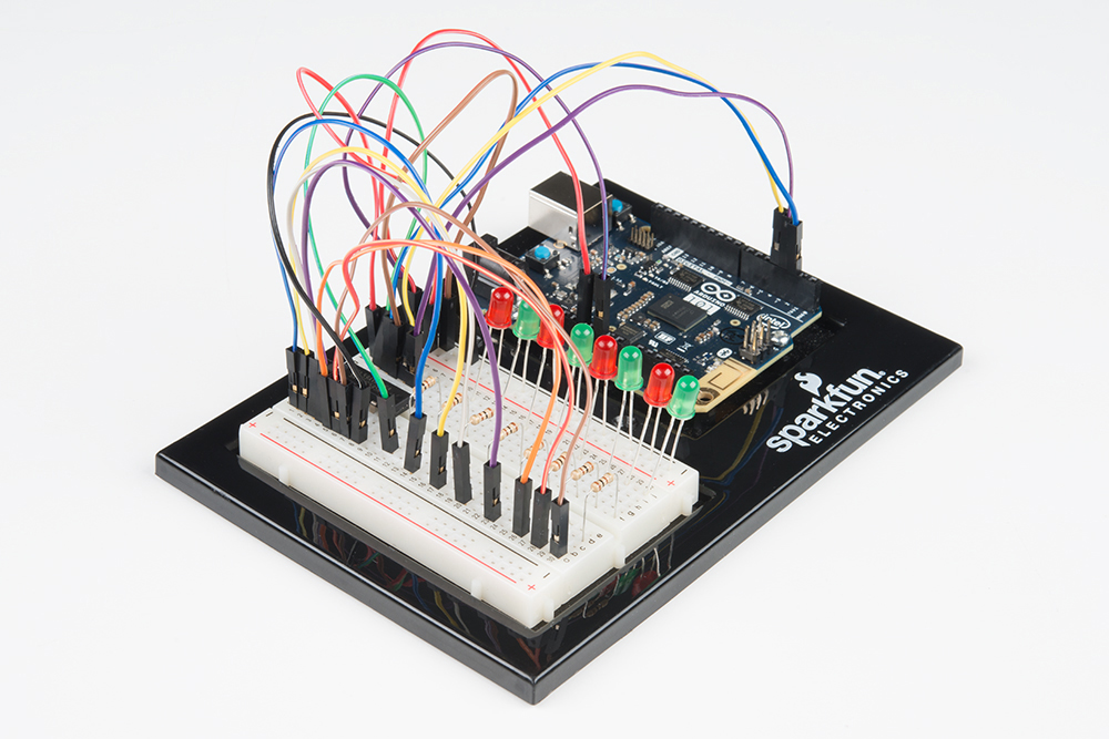
This happened to us a couple of times. It happens when the chip is inserted backward. If you fix it quickly, nothing will break.
Sorry to sound like a broken record, but it is probably something as simple as a crossed wire.
In this experiment, you will learn how to use an LCD. An LCD (Liquid Crystal Display) is a simple screen that can display commands, bits of information, or readings from your sensor -- all depending on how you program your board. In this circuit, you’ll learn the basics of incorporating an LCD into your project.
You will need the following parts:
If you are conducting this experiment and didn't get the SIK, we suggest using these parts:
You will also need either an Arduino 101 OR Genuino 101 board.

The 101 SIK includes a Liquid Crystal Display (LCD) screen. This screen is similar to one that you may find in your microwave, on your dashboard in your car, or if you are old enough to remember, a Speak and Spell. LCD screens are a great way to display data or information from your 101 board without having to have it connected to your laptop.
This LCD screen has a total of 32 possible character spaces arranged in a grid consisting of two rows of 16 characters. The LCD is controlled through a library that makes using it with the 101 board much easier. The wiring looks a little overwhelming, but it is a worthwhile challenge.
**Pro Tip: When wiring the LCD screen, start from one side of the LCD pins and work in toward the center. Once you reach an unpopulated pin, switch to the other side and repeat the process. This method will help prevent accidentally missing a pin or incorrectly wiring it up. **
Ready to start hooking everything up? Check out the wiring diagram below to see how everything is connected.
| Polarized Components | Pay special attention to the component’s markings indicating how to place it on the breadboard. Polarized components can only be connected to a circuit in one direction. |
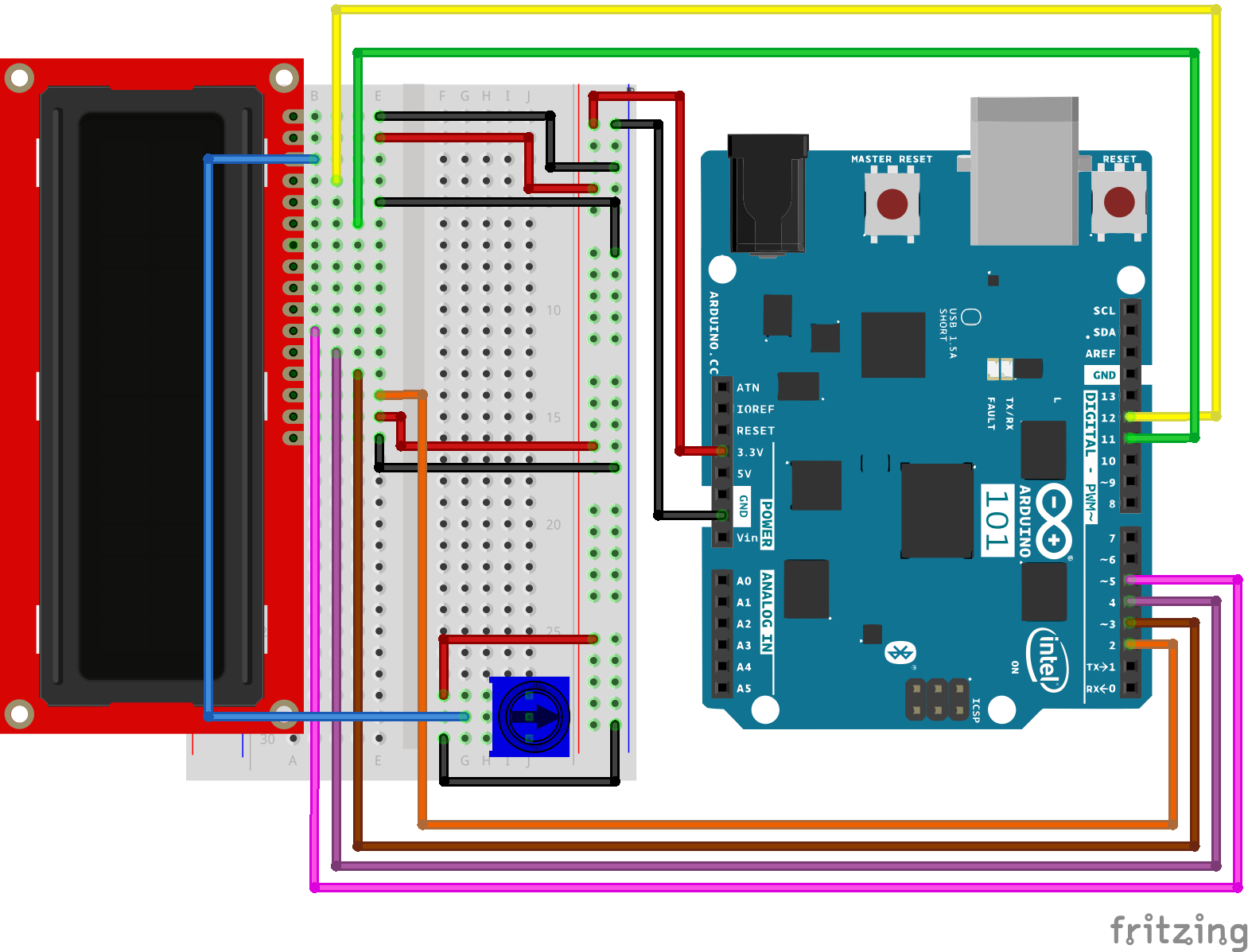
Open the Arduino IDE software on your computer. Coding in the Arduino language will control your circuit. Open the code for Circuit 17 by accessing the “101 SIK Guide Code” you downloaded and placed into your “Examples” folder earlier.
To open the code go to: File > Examples > 101 SIK Guide Code > Circuit_17
You can also copy and paste the following code into the Arduino IDE. Hit upload, and see what happens!
language:cpp
/*
SparkFun Inventor's Kit
Example sketch 17

LIQUID CRYSTAL DISPLAY (LCD)

  This sketch will show you how to connect an LCD to your Arduino
  and display any data you wish.

This sketch was written by SparkFun Electronics,
with lots of help from the Arduino community.
This code is completely free for any use.
Visit https://www.sparkfun.com/products/12060 for SIK information.
Visit http://www.arduino.cc to learn more about Arduino.
*/

// Load the LiquidCrystal library, which will give us
// commands to interface to the LCD:

#include <LiquidCrystal.h>

// Initialize the library with the pins we're using.
// (Note that you can use different pins if needed.)
// See http://arduino.cc/en/Reference/LiquidCrystal
// for more information:

LiquidCrystal lcd(12,11,5,4,3,2);

void setup()
{
  // The LiquidCrystal library can be used with many different
  // LCD sizes. We're using one that's 2 lines of 16 characters,
  // so we'll inform the library of that:

  lcd.begin(16, 2);

  // Data sent to the display will stay there until it's
  // overwritten or power is removed. This can be a problem
  // when you upload a new sketch to the Arduino but old data
  // remains on the display. Let's clear the LCD using the
  // clear() command from the LiquidCrystal library:

  lcd.clear();

  // Now we'll display a message on the LCD!

  // Just as with the Arduino IDE, there's a cursor that
  // determines where the data you type will appear. By default,
  // this cursor is invisible, though you can make it visible
  // with other library commands if you wish.

  // When the display powers up, the invisible cursor starts
  // on the top row and first column.

  lcd.print("hello, world!");

  // Adjusting the contrast (IMPORTANT!)

  // When you run the sketch for the first time, there's a
  // very good chance you won't see anything on the LCD display.
  // This is because the contrast likely won't be set correctly.
  // Don't worry, it's easy to set, and once you set it you won't
  // need to change it again.

  // Run the sketch, then turn the potentiometer until you can
  // clearly see the "hello, world!" text. If you still can't
  // see anything, check all of your connections, and ensure that
  // the sketch was successfully uploaded to the Arduino.
}

void loop()
{
  // You can move the invisible cursor to any location on the
  // LCD before sending data. Counting starts from 0, so the top
  // line is line 0 and the bottom line is line 1. Columns range
  // from 0 on the left side, to 15 on the right.

  // In additon to the "hello, world!" printed above, let's
  // display a running count of the seconds since the Arduino
  // was last reset. Note that the data you send to the display
  // will stay there unless you erase it by overwriting it or
  // sending an lcd.clear() command.

  // Here we'll set the invisible cursor to the first column
  // (column 0) of the second line (line 1):

  lcd.setCursor(0,1);

  // Now we'll print the number of seconds (millis() / 1000)
  // since the Arduino last reset:

  lcd.print(millis()/1000);

  // TIP: Since the numeric data we're sending is always growing
  // in length, new values will always overwrite the previous ones.
  // However, if you want to display varying or decreasing numbers
  // like a countdown, you'll find that the display will leave
  // "orphan" characters when the new value is shorter than the
  // old one.

  // To prevent this, you'll need to erase the old number before
  // writing the new one. You can do this by overwriting the
  // last number with spaces. If you erase the old number and
  // immediately write the new one, the momentary erase won't
  // be noticeable. Here's a typical sequence of code:

  // lcd.setCursor(0,1);   // Set the cursor to the position
  // lcd.print("       "); // Erase the largest possible number
  // lcd.setCursor(0,1);   // Reset the cursor to the original position
  // lcd.print(millis()/1000); // Print our value

  // NEXT STEPS:

  // Now you know the basics of hooking up an LCD to the Arduino,
  // and sending text and numeric data to the display!

  // The LCD library has many commands for turning the
  // cursor on and off, scrolling the screen, etc. See:
  // http://arduino.cc/en/Reference/LiquidCrystal
  // for more information.

  // Arduino also comes with a number of built-in examples
  // showing off the features of the LiquidCrystal library.
  // These are locted in the file/examples/LiquidCrystal menu.

  // Have fun, and let us know what you create!
  // Your friends at SparkFun.
}
#include <LiquidCrystal.h>
This bit of code tells your Arduino IDE to include the library for a simple LCD display. Without it, none of the commands will work, so make sure you include it!
lcd.print(“hello, world!”);
This is the first time you’ll fire something up on your screen. You may need to adjust the contrast to make it visible. Twist the potentiometer until you can clearly see the text.
lcd.clear();
Yep, you guessed it. This method is used to clear whatever data is printed to the LCD.
lcd.setCursor(0,1);
If you look closely you will notice that each character has a little box around it and these boxes are in a 2x16 grid. The first number in this method is the column (zero based counting ... gotta get used to that!), and the second number is the row. So this value of 0,1 is the first column, second row.
Initially, you should see the words “hello, world!” pop up on your LCD. Remember you can adjust the contrast using the potentiometer if you can’t make out the words clearly. If you have any issues, make sure your code is correct and double-check your connections. See also the Troubleshooting section below.
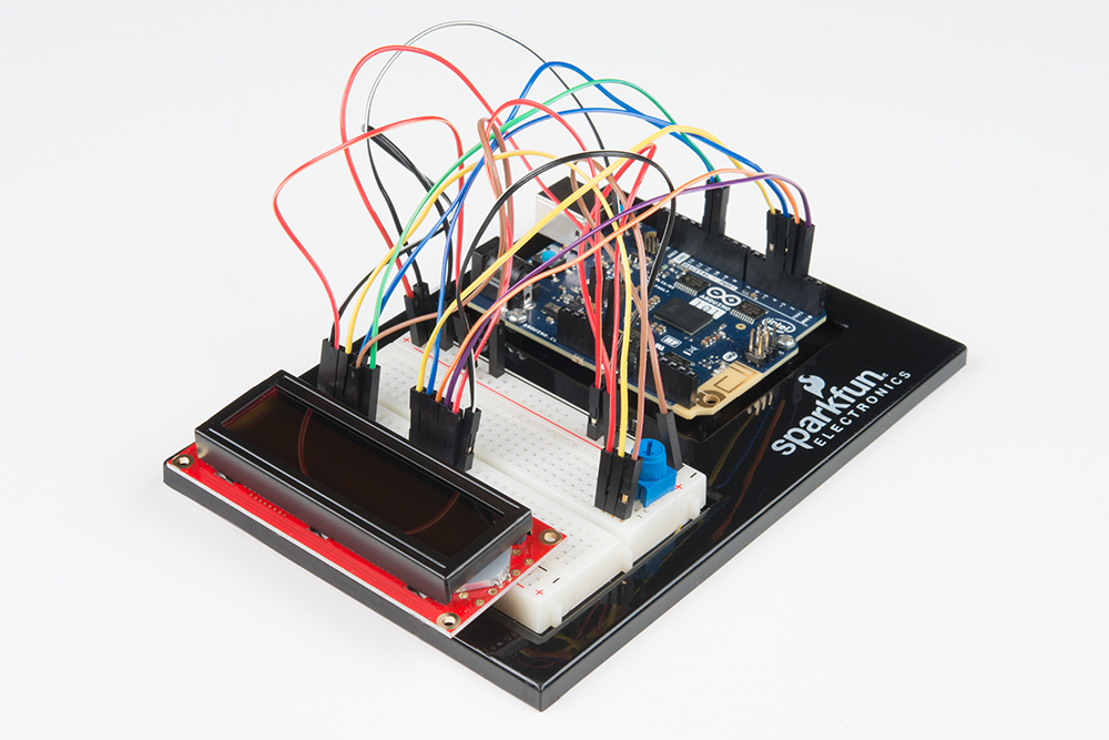
Fiddle with the contrast by twisting the potentiometer. If it’s incorrectly adjusted, you won’t be able to read the text.
Double check the code, specifically that you include the LCD library.
Double check your connections to your breadboard and 101 board.
In Experiment 13, you played around with using different inputs to control a motor's speed and direction. In this experiment you will do something similar but use the on-board accelerometer on the Arduino 101 board as an input.
The accelerometer measures gravitational forces being applied to the sensor in different directions. You can extrapolate a lot of information from accelerometer data if it is being moved around. But it is also handy for figuring out which way is down when it is sitting still! Earth's gravity is an ever-present force that can be measured by the accelerometer. We will use it in this way to determine the orientation of your Arduino 101 board, and from there have your motor drive forward, backward or do nothing. Lets get to it!
You will need the following parts:
If you are conducting this experiment and didn't get the SIK, we suggest using these parts:
You will also need either an Arduino 101 OR Genuino 101 board.
Before continuing with this experiment, we recommend you be familiar with the concepts in the following tutorials:
Accelerometers are devices that measure acceleration, which is the rate of change of the velocity of an object. They measure in meters per second squared (m/s2) or in G-forces (g). A single G-force for us here on planet Earth is equivalent to 9.8 m/s2, but this does vary slightly with elevation (and will be a different value on different planets due to variations in gravitational pull). Accelerometers are useful for sensing vibrations in systems or for orientation applications.
Ready to start hooking everything up? Check out the wiring diagram below to see how everything is connected.
| Polarized Components | Pay special attention to the component’s markings indicating how to place it on the breadboard. Polarized components can only be connected to a circuit in one direction. |
Open the Arduino IDE software on your computer. Coding in the Arduino language will control your circuit. Open the code for Circuit 18 by accessing the “101 SIK Guide Code” you downloaded and placed into your “Examples” folder earlier.
To open the code go to: File > Examples > 101 SIK Guide Code > Circuit_18
You can also copy and paste the following code into the Arduino IDE. Hit upload, and see what happens!
language:cpp
/*
SparkFun Inventor's Kit
Example sketch 18

Controlling a Motor Using an Accelerometer

  Use the on-board accelerometer of the 101 board as an input to control
  a motor based on its orientation in space. If you tilt the 101 to the left,
  the motor spins in one direction; tilted to the right, it spins the opposite direction; and if it
  is flat, the motor stops.

This sketch was written by SparkFun Electronics, and based on the Orientation example
in the CurieIMU Library Examples
This code is completely free for any use.
Visit http://learn.sparkfun.com/products/2 for SIK information.
Visit http://www.arduino.cc to learn more about Arduino.
*/

#include "CurieIMU.h"

const int DIR_A = 4;
const int DIR_B = 5;
const int PWM = 6;

// previous orientation (for comparison). Start at (-1) to start with


void setup()
{
 //set motor control pins to OUTPUT
pinMode(DIR_A, OUTPUT);
pinMode(DIR_B, OUTPUT);
pinMode(PWM, OUTPUT);

 // Start the acceleromter
 CurieIMU.begin();

// Set the accelerometer range to 2G
CurieIMU.setAccelerometerRange(2);
}

void loop()
{
 // read accelerometer:
 int x = CurieIMU.readAccelerometer(X_AXIS);
 int y = CurieIMU.readAccelerometer(Y_AXIS);
 int z = CurieIMU.readAccelerometer(Z_AXIS);

 // calculate the absolute values, to determine the largest
 int absX = abs(x);
 int absY = abs(y);
 int absZ = abs(z);

if ( (absZ > absX) && (absZ > absY))
{
 // base orientation on Z
 if (z > 0)
 {
  brake();
 }
}

 //else if Y is greater than X and Z its on edge
 else if ( (absY > absX) && (absY > absZ))
 {
  // if Y is positive orientation (digital pins up)and is set to 1
  if (y > 0)
  {
    forward();
  }
  //the Y is in the negative orientation (analog pins up) and is set to 2
  else
  {
    reverse();
  }
}
}
//custom function for driving the motor forward
void forward()
{
  digitalWrite(DIR_A, HIGH);
  digitalWrite(DIR_B, LOW);
  digitalWrite(PWM, HIGH);
}

//custom function for driving the motor in reverse
void reverse()
{
  digitalWrite(DIR_A, LOW);
  digitalWrite(DIR_B, HIGH);
  digitalWrite(PWM, HIGH);
}

//custom function for braking the motor
void brake()
{
  digitalWrite(DIR_A, LOW);
  digitalWrite(DIR_B, LOW);
  digitalWrite(PWM, LOW);
}
#include "CurieIMU.h"
The Arduino's serial port can be used to receive as well as send data. Because data could arrive at any time, the Arduino 101 board stores, or "buffers," data coming into the port until you're ready to use it. The Serial.available() command returns the number of characters that the port has received, but haven't been used by your sketch yet. Zero means no data has arrived.
int x = CurieIMU.readAccelerometer(X_AXIS);
We read the accelerometer value by passing the constant of X_AXIS to the readAccelerometer method of the CurieIMU. This will return the real time reading from the sensor. To read other Axis you can pass it the constants of X_AXIS, Y_AXIS and Z_AXIS.
int absX = abs(x);
In this experiment we are not necessarily interested in the positive or negative values. We just want to know which ones are the largest, and we can make a decision from there. We used the 'abs()' function which takes the absolute value of a number (basically removes the (-) sign). We store that in a local variable called 'absX' so that if we ever want to access the raw x value, we can still do that.
language:cpp
//if Z axis is greater than X and Y its facing upright
if ( (absZ > absX) && (absZ > absY))
{
 // base orientation on Z
 if (z > 0)
 {
  brake();
 }
}

 //else if Y is greater than X and Z its on edge
 else if ( (absY > absX) && (absY > absZ))
 {
  // if Y is positive orientation (digital pins up)and is set to 1
  if (y > 0)
  {
    forward();
  }
  //the Y is in the negative orientation (analog pins up) and is set to 2
  else
  {
    reverse();
  }
}
Once we have the accelerometer readings in absolute value, we can compare them using an if() statement. In this example we are only looking to compare the values that have to do with tipping the board to the left and right, but it still takes all three axes to figure that out. For example, if Y is greater than X, the Y axis is pointed down (pointed at the direction of gravity). We then do a final comparison to see if it's greater than 0 to make sure it is in the positive direction. We set the direction of the motor based on those comparisons.
Once the code is uploaded to the 101 board, pick up the 101 and tip it to the left (analog input pins down). The motor should start running in one direction. Now tip it in the opposite direction (digital GPIO pins down), and the motor should run in the opposite direction. When you lay the board flat the motor should stop. If not, see the Troubleshooting section below.
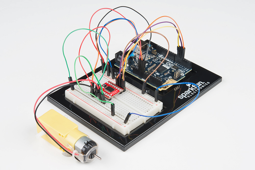
Make sure you have the motor controller wired up correctly. That is a lot of wires!
Double check that your code uploaded to your 101. Sometimes it takes awhile to upload to the 101 board, so be patient!
Sometimes the Arduino will disconnect from the computer. Try unplugging and then replugging it into your USB port.
One of the strengths of the 101 board is that it has some pretty sophisticated technology when it comes to gesture and movement recognition. This is all made possible through the Inertial Measurement Unit (IMU) on the 101 board. The IMU measures both accelerometer (gravitational force) and gyroscope (rotation) data. We played around with the accelerometer in Experiment 18. Let's dig a little deeper and leverage the Curie module, which can make sense of the data to determine if you are taking a step and counting them, detecting if you are tapping on the board and even its orientation in space.
As an example of using the combination of the IMU and the the Curie module, we will create a simple RGB circuit that will blink green twice when you double tap on the top of the 101 board and blink red twice when you double tap on the bottom of the 101 board.
You will need the following parts:
If you are conducting this experiment and didn't get the SIK, we suggest using these parts:
You will also need either an Arduino 101 OR Genuino 101 board.
Before continuing with this experiment, we recommend you be familiar with the concepts in the following tutorials:
An Inertial Measurement Unit (IMU) is a combination of sensors used to determine the sensors' orientation in three-dimensional space. The 101 uses an accelerometer and gyroscope to detect physical orientation (by measuring gravity pulling on the sensor), and a gyroscope to detect rotational motion.
The 101 board can translate the IMU data into certain pre-programmed gestures such as: taking a step, tapping or double tapping on it, or dropping the board. This experiment will focus on detecting taps/double taps, but please play around with the other example code found under File > Examples > CurieIMU.
Note: The 101 board has an IMU populated on the board and is accessed through the Arduino library. There is no wiring required to use the IMU!
Ready to start hooking everything up? Check out the wiring diagram below to see how everything is connected.
| Polarized Components | Pay special attention to the component’s markings indicating how to place it on the breadboard. Polarized components can only be connected to a circuit in one direction. |
Open the Arduino IDE software on your computer. Coding in the Arduino language will control your circuit. Open the code for Circuit 19 by accessing the “101 SIK Guide Code” you downloaded and placed into your “Examples” folder earlier.
To open the code go to: File > Examples > SIK Guide Code > Circuit_19
You can also copy and paste the following code into the Arduino IDE. Hit upload, and see what happens!
language:cpp
/*
SparkFun Inventor's Kit
Example sketch 19

TAP DETECTION

Use the 101 board's on-board IMU to detect a tap and double tap and react accordingly.

This sketch was written by SparkFun Electronics,
with lots of help from the Arduino community.
This code is completely free for any use.
Visit http://learn.sparkfun.com/products/2 for SIK information.
Visit http://www.arduino.cc to learn more about Arduino.
*/

#include "CurieIMU.h"

void setup()
{

 pinMode(5, OUTPUT);
 pinMode(6, OUTPUT);

 // Initialise the IMU
 CurieIMU.begin();
 CurieIMU.attachInterrupt(eventCallback);

 // Increase Accelerometer range to allow detection of stronger taps (< 4g)
 CurieIMU.setAccelerometerRange(3);

 // Reduce threshold to allow detection of weaker taps (>= 750mg)
 CurieIMU.setDetectionThreshold(CURIE_IMU_TAP, 750); // (750mg)

 // Set the time window for 2 taps as a double tap (<= 250 milliseconds)
 CurieIMU.setDetectionDuration(CURIE_IMU_DOUBLE_TAP, 250);

 // Enable Double-Tap detection
 CurieIMU.interrupts(CURIE_IMU_DOUBLE_TAP);
 }

void loop()
{
 // nothing happens in the loop because all the action happens
 // in the callback function.
 }

static void eventCallback()
{
 if (CurieIMU.getInterruptStatus(CURIE_IMU_DOUBLE_TAP)) {
    if (CurieIMU.tapDetected(Z_AXIS, NEGATIVE))
    {
    digitalWrite(5, HIGH);
    digitalWrite(6, LOW);
    delay(250);
    digitalWrite(5, LOW);
    digitalWrite(6, LOW);
    delay(250);
    digitalWrite(5, HIGH);
    digitalWrite(6, LOW);
    delay(250);
    digitalWrite(5, LOW);
    digitalWrite(6, LOW);
    delay(250);
    }
   else if (CurieIMU.tapDetected(Z_AXIS, POSITIVE))
   {
    digitalWrite(5, LOW);
    digitalWrite(6, HIGH);
    delay(250);
    digitalWrite(5, LOW);
    digitalWrite(6, LOW);
    delay(250);
    digitalWrite(5, LOW);
    digitalWrite(6, HIGH);
    delay(250);
    digitalWrite(5, LOW);
    digitalWrite(6, LOW);
    delay(250);
   }
  else
  {
  digitalWrite(5, LOW);
  digitalWrite(6, LOW);
  }
 }
}
CurieIMU.begin();
Initialize or start using the on-board IMU. Without this the 101 board would never register any IMU data.
CurieIMU.attachInterrupt(eventCallback);
Interrupts are events that interrupt the loop and tell the 101 board to do something immediately. The 101 then jumps out of the loop, does that thing, and then gets back into the loop. The interrupt specifies a function to be done when the interrupt is triggered. In this case eventCallback.
 // Reduce threshold to allow detection of weaker taps (>= 750mg)
 CurieIMU.setDetectionThreshold(CURIE_IMU_TAP, 750); // (750mg)

 // Set the time window for 2 taps as a double tap (<= 250 milliseconds)
 CurieIMU.setDetectionDuration(CURIE_IMU_DOUBLE_TAP, 250);
To use the IMU to detect a double tap, some setup is required. You need to set a force threshold for both a hard tap as well as a softer tap. You also need to specify a duration for a double tap so that the Curie can tell the difference between a single tap and a double tap.
CurieIMU.interrupts(CURIE_IMU_DOUBLE_TAP); Finally, we attach the interrupt to the double tap event. So any time a double tap event happens, the 101 board will execute the eventCallback function.
Once the code is uploaded the RGB should be off. Pick up the board and double tap the top of the board with your finger at a rhythm and timing that is similar to a mouse double click. The RGB should blink the color green twice and then turn off again. If you do the same thing with the bottom of the board, it will blink red.
Double check that you have an #include "CurieIMU.h" statement. If you do, make sure the header file name is in quotes and not chevrons.
The 101 is looking for a specific timing range for a double tap. Try speeding up your taps or adjusting the double tap timing in the CurieIMU.setDetectionDuration(CURIE_IMU_DOUBLE_TAP, 250); method.
You can set the sensitivity of the accelerometer. The example is set to 2Gs or twice the amount of gravity we normally experience on Earth. If you make that smaller, it will increase the sensitivity.
Microcontrollers are really good at keeping time in terms of their own timing. What we mean by that is their operational time; they function on an internal clock signal that allows you to keep track of milliseconds and microseconds since being powered up. But microcontrollers don't have any way of knowing real time, which is the time we all base our days and schedules around.
In this experiment you will set the clock and then display the date and time on the LCD screen you learned how to use in Experiment 17.
Note: The 101 board doesn't have a backup battery for the RTC (Real Time Clock), so if you unplug the board or your batteries die, you will have to reset the RTC in code or develop a circuit that allows you to adjust the time.
You will need the following parts:
If you are conducting this experiment and didn't get the SIK, we suggest using these parts:
You will also need either an Arduino 101 OR Genuino 101 board.
Before continuing with this experiment, we recommend you be familiar with the concepts in the following tutorial:
A microcontroller performs well at keeping operational time, the timing required to do its job. Microcontrollers generally keep track of milliseconds since being powered on. However, they do a terrible job of keeping track of the time on which we, as human beings, function ("real time"). Microcontrollers use a Real Time Clock (RTC) to keep track of a set beginning and time moving forward.
The RTC keeps track of the hours, minutes and seconds of a clock as well as the day, month and year of the calendar. On the 101 board, this requires you to set the time and date when you first power it up. From that point forward it should keep accurate time. You can then use the time to trigger events to happen at a specific time or day, or even use it as a time stamp to log data.
Note: If the 101 board loses power, you will need to reset the clock in your code. Also, the RTC is an on-board component of the 101 board and requires no further wiring.
Ready to start hooking everything up? Check out the wiring diagram below to see how everything is connected.
| Polarized Components | Pay special attention to the component’s markings indicating how to place it on the breadboard. Polarized components can only be connected to a circuit in one direction. |
Open the Arduino IDE software on your computer. Coding in the Arduino language will control your circuit. Open the code for Circuit 20 by accessing the “101 SIK Guide Code” you downloaded and placed into your “Examples” folder earlier.
To open the code go to: File > Examples > 101 SIK Guide Code > Circuit_20
You can also copy and paste the following code into the Arduino IDE. Hit upload, and see what happens!
language:cpp
/*
SparkFun Inventor's Kit
Example sketch 20

DISPLAYING THE DATE AND TIME

This sketch reads the RTC data and prints it on the LCD screen

This sketch was written by SparkFun Electronics,
with lots of help from the Arduino community.
This code is completely free for any use.
Visit http://learn.sparkfun.com/products/2 for SIK information.
Visit http://www.arduino.cc to learn more about Arduino.
*/

//include the CurieTime Library
#include <CurieTime.h>
#include <LiquidCrystal.h>

//instantiate the lcd
LiquidCrystal lcd(12, 11, 5, 4, 3, 2);

void setup()
{
  //start lcd at 16 x 2
  lcd.begin(16, 2);

  //clear the lcd
  lcd.clear();

  //set time to 1:35:24 on April 4th, 2016. Please change to your time / date
  setTime(1, 35, 24, 4, 10, 2016);
}

void loop()
{
 //create a character array of 16 characters for the time
 char clockTime[16];
 //use sprintf to create a time string of the hour, minte and seconds
 sprintf(clockTime, "    %2d:%2d:%2d    ", hour(), minute(), second());

 //create a character array of 15 characters for the date
 char dateTime[16];
 //use sprintf to create a date string from month, day and year
 sprintf(dateTime, "   %2d/%2d/%4d   ", month(), day(), year());

 //set cursor to column 0, row 0
 lcd.setCursor(0, 0);
 //print the date string over lcd
 lcd.print(dateTime);
 //set cursor to column 0, row 1
 lcd.setCursor(0, 1);
 //print the time string over lcd
 lcd.print(clockTime);
}
setTime(1,35,00,4,10,2016);
The RTC on the 101 board has to be set when you power it up. You do this by using the setTime() function. You pass setTime() 6 parameters in order of hour, minute, seconds, month, day, year. If your 101 board loses power for some reason, you will have to reset it using this function.
sprintf(dateTime, " %2d/%2d/%4d ", month(), day(), year()); sprintf() is a string-building function. It is a simple way to build strings by taking data and placing them in a character array, which in Arduino is basically a string. The funny %2d and %4d things are where the data is inserted with the number of digits specified, so %4d is 4 digits. Finally you pass the data you want to insert into the string as parameters. In this case month(), day(), and year().
Once the code is completely uploaded you should see two lines of text show up on your LCD screen. The first line should be the date (which should only change once a day), and the second line should be the current time, which you should see actively counting up. If not, see the Troubleshooting section below.
Fiddle with the contrast by twisting the potentiometer. If it’s incorrectly adjusted, you won’t be able to read the text.
Double check the code, specifically that you included the LCD library.
Double check your code. You probably have to update the setTime() function.
Here we are at the final experiment, and you have come full circle back to a single LED. This time the experiment has a twist! Instead of just blinking this lonely LED, you will control it through your phone or tablet!
The 101 board has Bluetooth Low Energy (BLE) built in. What that means for you is that you can start to control the 101 board from your phone. BLE uses a service/property-based approach to device communication. This approach makes developing across multiple devices easier in the long run, but if you are new to it, it can be quite daunting. This experiment covers loading an app to your device that will help with the communication, and we will go through an example sketch that uses BLE.
This is your final experiment, but in no way are you done learning about the 101 board. We highly recommend checking out the Arduino website for more information on the 101 board and how the supporting materials evolve and improve.
You will need the following parts:
If you are conducting this experiment and didn't get the SIK, we suggest using these parts:
You will also need either an Arduino 101 OR Genuino 101 board.
Before continuing with this experiment, we recommend you be familiar with the concepts in the following tutorials:
Bluetooth Low Energy (BLE) is a relatively newer communication protocol using Bluetooth. BLE is increasingly employed in wearable and Internet of Things (IoT) applications where power management is a concern, and your device needs to be able to communicate with a broad range of devices such as phones, cars and other BLE devices.
To standardize the communication protocol with a multitude of devices, BLE uses a General Attribute (GATT)-based system, which uses a hierarchy of what are called services based on the device function. For example, a Fitbit may have a heart rate service as well as a pedometer service. Each service can be assigned attributes. These attributes hold the raw data for the service.
An example attribute would be to communicate information about the device that it is communicating with as well as what data is important for a given service. In the example of a Fitbit, the number of steps or your pulse may be an attribute. The big idea is that there are services that allow devices to know what to expect from each other and to get on the same page so they can share attributes back and forth. In its simplest form, GATT allows devices to make assumptions about one another and get down to the important stuff ... sharing information you are trying to communicate.
**Note: BLE is built into the Curie module on the 101 board, and there is no wiring required beyond connecting what you want to control through BLE. **
Ready to start hooking everything up? Check out the wiring diagram below to see how everything is connected.
| Polarized Components | Pay special attention to the component’s markings indicating how to place it on the breadboard. Polarized components can only be connected to a circuit in one direction. |
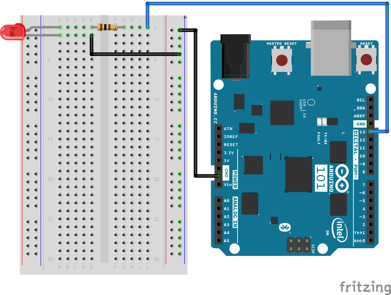
To get you up and running with using BLE with the Arduino 101 we recommend using the nRF Master Control Panel App. It is available for both Android and iOS devices, and the best part is that it's free!
To download the app go to either the Google Play store or the Apple App store and search for nRF. There are a number of other tools by nRF that we highly recommend you play with after getting BLE up and running, but for now we just need the Master Control Panel. Search, download and install the app -- then you're ready to go!
Open the Arduino IDE software on your computer. Coding in the Arduino language will control your circuit. Open the code for Circuit 21 by accessing the “101 SIK Guide Code” you downloaded and placed into your “Examples” folder earlier.
To open the code go to: File > Examples > 101 SIK Guide Code > Circuit_21
You can also copy and paste the following code into the Arduino IDE. Hit upload, and see what happens!
language:cpp
/*
SparkFun Inventor's Kit
Example sketch 21

BASIC BLE CONTROL

Turn an LED on and off using BLE and either a phone or tablet. Android and iOS devices only!

Based off of the BLE LED example written by Intel Corporation and included with the Curie BLE Arduino Library.

*/

 #include <CurieBLE.h>

BLEPeripheral blePeripheral;  // BLE Peripheral Device (the board you're programming)
BLEService ledService("19B10000-E8F2-537E-4F6C-D104768A1214"); // BLE LED Service


//set BLE characteristic
       BLEUnsignedCharCharacteristic switchCharacteristic("19B10001-E8F2-537E-4F6C-D104768A1214", BLERead | BLEWrite);

const int ledPin = 13; // pin to use for the LED

 void setup()
{
 // set LED pin to output mode
  pinMode(ledPin, OUTPUT);

  // set advertised local name and service UUID:
  blePeripheral.setLocalName("101 Board");
  blePeripheral.setAdvertisedServiceUuid(ledService.uuid());

  // add service and characteristic:
   blePeripheral.addAttribute(ledService);
   blePeripheral.addAttribute(switchCharacteristic);

   // set the initial value for the characeristic:
    switchCharacteristic.setValue(0);

   // begin advertising BLE service:
   blePeripheral.begin();
 }

void loop()
{
  // listen for BLE peripherals to connect:
 BLECentral central = blePeripheral.central();

 // if a central is connected to peripheral:
  if (central)
  {
   // while the central is still connected to peripheral:
    while (central.connected())
    {
      // if the remote device wrote to the characteristic,
      // use the value to control the LED:
      if (switchCharacteristic.written())
      {
          // any value other than 0, turn on the LED
         if (switchCharacteristic.value())
         {
         digitalWrite(ledPin, HIGH);
         }
      //else turn the LED off
       else
      {
      digitalWrite(ledPin, LOW);
      }
      }
     }
    }
  }
BLEService ledService("19B10000-E8F2-537E-4F6C-D104768A1214");
BLE is service based, and a number of services are predefined with a custom string called a Universally Unique Identifier (UUID). This string is 16 bytes long and, as the name states, is universally unique. This is instantiating the BLEService object ledService with a specific UUID.
switchCharacteristic("19B10001-E8F2-537E-4F6C-D104768A1214", BLERead | BLEWrite);
Characteristics and attributes are bundled underneath services. You can create characteristics with their own UUIDs and set them to readable, writable, or both. We opted for both. Notice that the characteristic UUID is one digit different from the Service UUID.
blePeripheral.setLocalName("101 Board");
You can name your 101 by using the setLocalName() method. You pass it a string in quotes. We recommend making this something that you can easily identify as yours, especially if you are using the 101 in the classroom.
   blePeripheral.setAdvertisedServiceUuid(ledService.uuid());

   // add service and characteristic:
   blePeripheral.addAttribute(ledService);
   blePeripheral.addAttribute(switchCharacteristic);

   // set the initial value for the characeristic:
   switchCharacteristic.setValue(0);

   // begin advertising BLE service:
   blePeripheral.begin();
In this chunk of code we add a service to our peripheral, then bind or add attributes to the peripheral. We add the ledService and control it through the switchCharacteristics. We finally set the starting value of the switchCharacteristics to 0 and start up the peripheral.
From there in the loop function we make sure there is a connection between our peripheral and a central device (a phone). While we have a connection, we check if there is a characteristic present and if it has been written to. If there is a value other than 0, we turn the LED on; if there is no value, or the value is 0, the LED is turned off.
Open up your Bluetooth connections on your device and start the Master Control Panel app. Scan for devices, select your 101, and connect to it.

Once it connects, open up the unknown service and select the switchvalue. Click on the upload logo (arrow pointing up). This will bring up a dialog box. Enter a number other than 0 and click send.
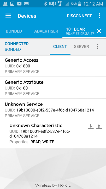
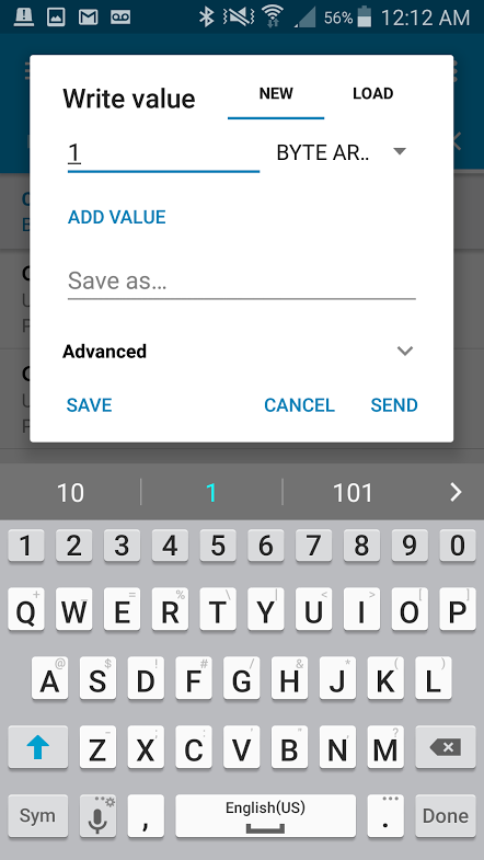
The LED should turn on! Bring up the same dialog box, enter the number 0 and click send. The LED should turn off.
You know the drill: check your wiring, check to see if the LED is inserted backward.
Make sure that your sketch uploaded! You have to upload the sketch for the BLE signal to be broadcast from the 101 board.
Try restarting your phone's or tablet's Bluetooth and scanning for local devices again.
The Arduino 101 board add-on only seems to work with Arduino IDE version 1.6.x. Make sure to use a previous version of the Arduino IDE if you are having problems installing the Arduino 101 board add-on. We were unable to get it to install on Arduino IDE v1.8.x.
For those trying to use the BLE on Arduino 101, make sure to use the Intel Curie Boards by Intel with v1.0.7 . The latest version (2.0.2) does not work as expected for certain examples like the BLE example. The Arduino forums even say that the board version is broken. Code will compile in the Arduino IDE but the experiments will not work as expected.
If you have already uploaded to the board, you can roll back to the previous version by following the instructions listed in the upload error:
Starting download script...
!! BLE firmware version is not in sync with CurieBLE library !!
* Set Programmer to "Arduino/Genuino 101 Firmware Updater"
* Update it using "Burn Bootloader" menu
An error occurred while uploading the sketch
You can use Arduino IDE v1.8.2 or v1.8.3 and selecting Tools>Programmer:Arduino/Genuino 101 Firmware Updater". You will then need to click on Tools>Burn Bootloader . And yes, you do not need a programmer when rolling back to the previous board definition. Just have the Arduino 101 connected to their computer via USB and the correct board definition/COM port selected.
After uploading with the correct board definition, the experiments with the BLE should work as expected.
If you are trying to roll back the Arduino 101 to a previous board version and see this error:
Reset the board before proceeding...
find: sensor: No such file or directory
find: sensor: No such file or directory
find: sensor: No such file or directory
.
.
.
Error while burning bootloader
, it is because the computer is not able to find a certain file on your computer due to the way that the Arduino 101 board definitions were installed. You can try re-installing, deleting temporary files, and reinstalling the Arduino IDE version. If you are still having issues, try a different computer. A technical support representative had to use a known good Mac [ OSX Lion v10.7.5 ] to roll back. One thing to note is that the Mac was not able to upload to the Arduino 101 but a different Windows computer was able to do it using the previous board version.
There are tons of sensors and shields that you can hook up to your Arduino 101 board to help take your projects to the next level. Here is some further reading that may help you along in learning more about the world of electronics.
For more info on Arduino, check out these tutorials:
For more hardware-related tutorials, give these a read:
learn.sparkfun.com | CC BY-SA 3.0 | SparkFun Electronics | Niwot, Colorado