SIK Experiment Guide for the Arduino 101/Genuino 101 Board (Spanish)
This Tutorial is Retired!
This tutorial covers concepts or technologies that are no longer current. It's still here for you to read and enjoy, but may not be as useful as our newest tutorials.
 D___Run___
 Experimento 16: Usar un registro de desplazamientos
Introducción
Ahora vamos a entrar en el mundo de los IC (circuitos integrados) sin procesar. En este experimento, aprenderá a usar un registro de desplazamiento. El registro de desplazamiento le proporcionará a la placa 101 ocho salidas adicionales y utilizará solo tres pines de la placa. Para este experimento, usará un registro de desplazamiento para controlar ocho LED. Dos LED más que en el experimento 4.
Elementos necesarios
Necesitará los siguientes elementos:
- 1 placa de pruebas
- 1 placa Arduino 101 o Genuino 101
- 8 LED
- 8 resistencias de 330 Ω
- 1 registro de desplazamiento de 8 bits 74HC595
- 19 cables puente
¿No tiene el SIK?
Si está realizando este experimento y no dispone del SIK, le sugerimos que use estos elementos:


También necesitará una placa Arduino 101 O Genuino 101.

Arduino 101
DEV-13787
Genuino 101
DEV-13984Lectura sugerida
Antes de continuar con este experimento, le recomendamos que se familiarice con los conceptos en los siguientes tutoriales:
Presentación del registro de desplazamiento
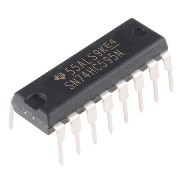
El registro de desplazamiento es un circuito integrado (IC). Los IC son diminutos conjuntos cerrados de plástico que albergan los circuitos más populares y que se usan con más frecuencia. Los IC actúan como componentes individuales que realizan un trabajo específico y simplifican lo que solía ser un diseño de circuito que requería mucho espacio y tiempo.
El registro de desplazamiento básicamente le permite controlar hasta ocho salidas mientras solo usa tres pines en la placa 101. Permite controlar más salidas con menos pines en comparación con el experimento 4, donde usó seis pines para seis salidas individuales.
Piénselo de esta manera: los datos que entran en el registro de desplazamiento serían como un tren de ocho vagones diferentes. Si un vagón está repleto de carga, los datos representan un 1. Si el vagón está vacío, los datos representan un 0. Cuando todo el tren entra en el registro de desplazamiento, se separa y cada vagón se dirige hacia su propia vía. Estas vías se pueden traducir en los ochos pines de entrada del registro de desplazamiento. Si el vagón está lleno (1), el pin que está activado tendrá el valor ALTO; si el vagón está vacío (0), el pin tendrá el valor BAJO. Si envía de manera constante un tren detrás de otro al registro de desplazamiento, puede encender los LED o controlar algo como una pantalla de 7 segmentos para contar hacia atrás o incluso una gran cantidad de motores que se encienden en momentos diferentes. Todo esto sucede simplemente enviando trenes al registro de desplazamiento con diferentes patrones de 1 y 0.
Para obtener más información acerca de trenes registros de desplazamiento, eche un vistazo a nuestro tutorial de registros de desplazamiento.
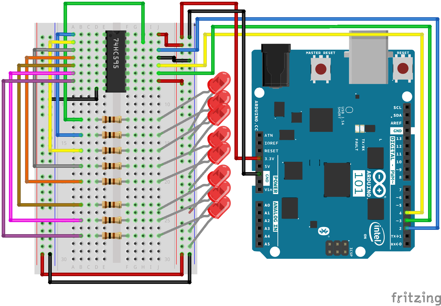
Conexión del hardware
¿Está preparado para comenzar a conectar todo? Consulte el diagrama de cableado siguiente para ver cómo está conectado todo.
| Componentes polarizados | Preste especial atención a las marcas de los componentes que indican cómo colocarlo en la placa de pruebas. Los componentes polarizados solo se pueden conectar a un circuito en una sola dirección. |
Diagrama de cableado del experimento
Abrir el boceto
Abra el software IDE de Arduino en su ordenador. La codificación en el lenguaje de Arduino controlará el circuito. Abra el código del circuito 16; para ello, acceda a "101 SIK Guide Code" (Guía de códigos de SIK 101) que ha descargado y guardado en la carpeta "Examples" (Ejemplos) anteriormente.
Para abrir el código vaya a: File > Examples > 101 SIK Guide Code > Circuit_16 (Archivo > Ejemplos > Guía de códigos de SIK 101 > Circuito_16)
También puede copiar y pegar el siguiente código en el IDE de Arduino. Cárguelo y vea qué es lo que ocurre.
language:cpp
/*
SparkFun Inventor's Kit
Example sketch 16

SHIFT REGISTER

  Use a shift register to turn three pins into eight (or more!)
  outputs

This sketch was written by SparkFun Electronics,
with lots of help from the Arduino community.
This code is completely free for any use.
Visit http://learn.sparkfun.com/products/2 for SIK information.
Visit http://www.arduino.cc to learn more about Arduino.
*/

// Pin definitions:
// The 74HC595 uses a type of serial connection called SPI
// (Serial Peripheral Interface) that requires three pins:

int datapin = 2;
int clockpin = 3;
int latchpin = 4;

// We'll also declare a global variable for the data we're
// sending to the shift register:

byte data = 0;

void setup()
{
  // Set the three SPI pins to be outputs:

  pinMode(datapin, OUTPUT);
  pinMode(clockpin, OUTPUT);
  pinMode(latchpin, OUTPUT);
}

void loop()
{
  // We're going to use the same functions we played with back
  // in circuit 04, "Multiple LEDs," we've just replaced
  // digitalWrite() with a new function called shiftWrite()
  // (see below). We also have a new function that demonstrates
  // binary counting.

  // To try the different functions below, uncomment the one
  // you want to run, and comment out the remaining ones to
  // disable them from running.

  oneAfterAnother();      // All on, all off

  //oneOnAtATime();       // Scroll down the line

  //pingPong();           // Like above, but back and forth

  //randomLED();          // Blink random LEDs

  //marquee();

  //binaryCount();        // Bit patterns from 0 to 255
}

void shiftWrite(int desiredPin, boolean desiredState)

// This function lets you make the shift register outputs
// HIGH or LOW in exactly the same way that you use digitalWrite().

// Like digitalWrite(), this function takes two parameters:

//    "desiredPin" is the shift register output pin
//    you want to affect (0-7)

//    "desiredState" is whether you want that output
//    to be HIGH or LOW

// Inside the Arduino, numbers are stored as arrays of "bits,"
// each of which is a single 1 or 0 value. Because a "byte" type
// is also eight bits, we'll use a byte (which we named "data"
// at the top of this sketch) to send data to the shift register.
// If a bit in the byte is "1," the output will be HIGH. If the bit
// is "0," the output will be LOW.

// To turn the individual bits in "data" on and off, we'll use
// a new Arduino commands called bitWrite(), which can make
// individual bits in a number 1 or 0.
{
  // First we'll alter the global variable "data," changing the
  // desired bit to 1 or 0:

  bitWrite(data,desiredPin,desiredState);

  // Now we'll actually send that data to the shift register.
  // The shiftOut() function does all the hard work of
  // manipulating the data and clock pins to move the data
  // into the shift register:

  shiftOut(datapin, clockpin, MSBFIRST, data);

  // Once the data is in the shift register, we still need to
  // make it appear at the outputs. We'll toggle the state of
  // the latchPin, which will signal the shift register to "latch"
  // the data to the outputs. (Latch activates on the high-to
  // -low transition).

  digitalWrite(latchpin, HIGH);
  digitalWrite(latchpin, LOW);
}

/*
oneAfterAnother()

This function will light one LED, delay for delayTime, then light
the next LED, and repeat until all the LEDs are on. It will then
turn them off in the reverse order.
*/

void oneAfterAnother()
{
  int index;
  int delayTime = 100; // Time (milliseconds) to pause between LEDs
                       // Make this smaller for faster switching

  // Turn all the LEDs on:

  // This for() loop will step index from 0 to 7
  // (putting "++" after a variable means add one to it)
  // and will then use digitalWrite() to turn that LED on.

  for(index = 0; index <= 7; index++)
  {
    shiftWrite(index, HIGH);
    delay(delayTime);
  }

  // Turn all the LEDs off:

  // This for() loop will step index from 7 to 0
  // (putting "--" after a variable means subtract one from it)
  // and will then use digitalWrite() to turn that LED off.

  for(index = 7; index >= 0; index--)
  {
    shiftWrite(index, LOW);
    delay(delayTime);
  }
}

/*
oneOnAtATime()

This function will step through the LEDs, lighting one at at time.
*/

void oneOnAtATime()
{
  int index;
  int delayTime = 100; // Time (milliseconds) to pause between LEDs
                       // Make this smaller for faster switching

  // step through the LEDs, from 0 to 7

  for(index = 0; index <= 7; index++)
  {
    shiftWrite(index, HIGH);    // turn LED on
    delay(delayTime);       // pause to slow down the sequence
    shiftWrite(index, LOW); // turn LED off
  }
}

/*
pingPong()

This function will step through the LEDs, lighting one at at time,
in both directions.
*/

void pingPong()
{
  int index;
  int delayTime = 100; // time (milliseconds) to pause between LEDs
                       // make this smaller for faster switching

  // step through the LEDs, from 0 to 7

  for(index = 0; index <= 7; index++)
  {
    shiftWrite(index, HIGH);    // turn LED on
    delay(delayTime);       // pause to slow down the sequence
    shiftWrite(index, LOW); // turn LED off
  }

  // step through the LEDs, from 7 to 0

  for(index = 7; index >= 0; index--)
  {
    shiftWrite(index, HIGH);    // turn LED on
    delay(delayTime);       // pause to slow down the sequence
    shiftWrite(index, LOW); // turn LED off
  }
}

/*
randomLED()

This function will turn on random LEDs. Can you modify it so it
also lights them for random times?
*/

void randomLED()
{
  int index;
  int delayTime = 100; // time (milliseconds) to pause between LEDs
                       // make this smaller for faster switching

  // The random() function will return a semi-random number each
  // time it is called. See http://arduino.cc/en/Reference/Random
  // for tips on how to make random() more random.

  index = random(8);    // pick a random number between 0 and 7

  shiftWrite(index, HIGH);  // turn LED on
  delay(delayTime);     // pause to slow down the sequence
  shiftWrite(index, LOW);   // turn LED off
}

/*
marquee()

This function will mimic "chase lights" like those around signs.
*/

void marquee()
{
  int index;
  int delayTime = 200; // Time (milliseconds) to pause between LEDs
                       // Make this smaller for faster switching

  // Step through the first four LEDs
  // (We'll light up one in the lower 4 and one in the upper 4)

  for(index = 0; index <= 3; index++)
  {
    shiftWrite(index, HIGH);    // Turn a LED on
    shiftWrite(index+4, HIGH);  // Skip four, and turn that LED on
    delay(delayTime);       // Pause to slow down the sequence
    shiftWrite(index, LOW); // Turn both LEDs off
    shiftWrite(index+4, LOW);
  }
}

/*
binaryCount()

Numbers are stored internally in the Arduino as arrays of "bits,"
each of which is a 1 or 0\. Just like the base-10 numbers we use
every day, The position of the bit affects the magnitude of its
contribution to the total number:

Bit position   Contribution
0              1
1              2
2              4
3              8
4              16
5              32
6              64
7              128

To build any number from 0 to 255 from the above 8 bits, just
select the contributions you need to make. The bits will then be
1 if you use that contribution, and 0 if you don't.

This function will increment the "data" variable from 0 to 255
and repeat. When we send this value to the shift register and LEDs,
you can see the on-off pattern of the eight bits that make up the
byte. See http://www.arduino.cc/playground/Code/BitMath for more
information on binary numbers.
*/

void binaryCount()
{
  int delayTime = 1000; // time (milliseconds) to pause between LEDs
                        // make this smaller for faster switching

  // Send the data byte to the shift register:

  shiftOut(datapin, clockpin, MSBFIRST, data);

  // Toggle the latch pin to make the data appear at the outputs:

  digitalWrite(latchpin, HIGH);
  digitalWrite(latchpin, LOW);

  // Add one to data, and repeat!
  // (Because a byte type can only store numbers from 0 to 255,
  // if we add more than that, it will "roll around" back to 0
  // and start over).

  data++;

  // Delay so you can see what's going on:

  delay(delayTime);
}
Código a tener en cuenta
shiftOut(datapin, clockpin, MSBFIRST, data);
Podrá comunicarse con el registro de desplazamiento (y muchos otros elementos) con la SPI. Esta interfaz utiliza una línea de datos y una línea de reloj independiente que funcionan conjuntamente para enviar y recibir datos en la placa 101 a alta velocidad. El parámetro MSBFIRST especifica el orden en el que se envían los bits individuales; en este caso, primero enviaremos el bit más significativo.
bitWrite(data, desiredPin, desiredState);
Los bits son los fragmentos más pequeños de memoria en un ordenador; cada uno puede almacenar un valor: "1" o "0". Los números más grandes se almacenan como matrices de bits. A veces queremos manipular estos bits directamente; por ejemplo, ahora vamos a enviar ocho bits al registro de desplazamiento y queremos convertirlos en 1 o 0 para activar o desactivar los LED. Arduino tiene varios comandos, como bitWrite(), que nos permite hacer esto de manera fácil.
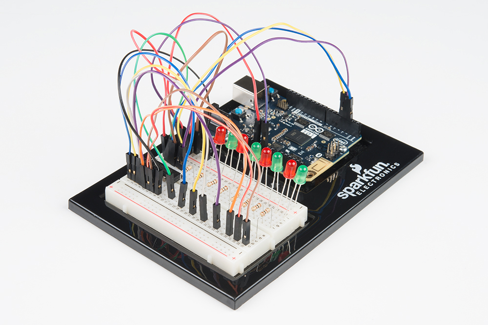
Lo que debería ver
Debería ver que los LED se encienden de manera similar al experimento 4 (pero esta vez, está utilizando un registro de desplazamiento). Si no es así, asegúrese de que ha montado el circuito correctamente y ha verificado y cargado código en la placa. Consulte la sección Solución de problemas.
Solución de problemas
El LED de alimentación de Arduino se apaga
Esto nos ha pasado varias veces. Esto ocurre cuando el chip se inserta al revés. Si lo soluciona rápido, nada se romperá.
No funciona bien
Sentimos parecer un disco rayado, pero probablemente es algo tan sencillo como un cable mal conectado.