Si4707 Hookup Guide
 jimblom
Firmware Upload
Click here to download our Si4707 I2C example code. You can also grab the code from the product's github repository.
This example code comes with three different files:
- si4707_example_code_i2c.ino - The main Arduino file. This is where
setup()andloop()are defined, as well as a few other global variables and useful functions. Mess with this one as you please. - si4707_system_functions.ino - This is where an array of "system" functions--nitty-gritty functions that create commands, and receive responses--are kept. It should be safe to ignore this file.
- si4707_definitions.h - This file defines all of the Si4707's register and property addresses. Don't change these definitions.
Open up si4707_example_code_i2c.ino, and head down to line 62. There's just one global variable that needs editing before you upload the sketch:
language:c
// Put the WB frequency you'd like to tune to here:
// The value should be in kHz, so 162475 equates to 162.475 MHz
// The sketch will attempt to tune to this frequency when it starts.
// Find your frequency here: http://www.nws.noaa.gov/nwr/indexnw.htm
unsigned long tuneFrequency = 162475; // 162.475 MHz
Edit the tuneFrequency variable to match the frequency of your nearest weather-band station. If you're not sure what that is, consult NOAA's Station Listing page. That variable should be your station's frequency in kHz. For example, if your local weather station is found at 162.500 MHz, set that variable to 162500.
With that, go ahead and upload your sketch. Then, open up the serial monitor, and make sure the baud rate is set to 9600 bps.
Upon reset, the Arduino will attempt to tune to your weather band station. Have a listen to your headphones. You should at least hear static, if not a weather station.
A configuration menu should also be printed out to the serial monitor:
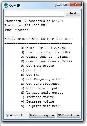
Try interacting with the config menu. If the volume is too loud, send a few -'s. Or just mute the volume by sending a lowercase m (an uppercase M will un-mute). You can also get the received signal strength (RSSI) and signal-to-noise ratio (SNR) of the received signal by sending r and S. Knowing those, you can try tuning up or down finely (u or d) or coarsely (U or D) to optimize the signal.
Understanding the Sketch
There are a few functions in the main example sketch that might come in handy, so we'll give a quick overview of them here.
Each of these functions has reliance on definitions in the other two files (si4707_definitions.h and si4707_system_functions.ino). Make sure each of those files are in the same directory as the main sketch and #include the definitions file near the top of the sketch. Wire.h should also be included:
language:c
#include "si4707_definitions.h"
#include <Wire.h>
initSi4707()
This function definition begins on line 194. Its purpose is to initiate communication with the Si4707 and to power up the device. This should be called at the beginning of any sketch that uses the IC.
language:C
// initSi4707 performs the following functions, in sequence:
//  * Initialize all pins connected to Si4707 (SEN, SCLK, SDIO, and RST)
//  * Starts up the Wire class - used for two-wire communication
//  * Applies a reset signal to the Si4707
//  * Sends the Power Up command to the Si4707
//  * Sends the GET REV command to verify communication, returns the final
//    two digits of the Part Number (should be 7)
byte initSi4707()
{
  // Set initial pin value: RST (Active-low reset)
  pinMode(rstPin, OUTPUT);  // Reset
  digitalWrite(rstPin, LOW);  // Keep the SI4707 in reset

  // Set initial pin value: SEN (I2C Address select)
  pinMode(senPin, OUTPUT);  // Serial enable
  if (SEN_ADDRESS)
    digitalWrite(senPin, HIGH);
  else
    digitalWrite(senPin, LOW);

  // Set initial pin values: SDIO and SCLK (serial data and clock lines)
  // Wire.begin() will take care of this
  Wire.begin();
  delay(1);  // Short delay before we take reset up

  // Raise RST, SCLK must not rise within 300ns before RST rises
  digitalWrite(rstPin, HIGH);
  delay(1);  // Give Si4707 a little time to reset

  // First, send the POWER UP command to turn on the Si4707.
  // The Si4707 must be powered up before sending any further commands.
  powerUp();

  // See Si4707_system_functions.ino for info on command_Get_Rev
  return command_Get_Rev(1);
}
setWBFrequency() and tuneWBFrequency()
These two functions can be used to change the received frequency of the Si4707. setWBFrequency(long freq) (definition begins on line 227) should be used to set the Si4707 to a specific WB frequency. The given parameter should be the desired frequency in kHz.
Directly below that function definition is one for tuneWBFrequency(signed char increment). This function can be used to change the radio's frequency in relation to the currently tuned station. The increment parameter can be a positive or negative number, telling the IC how many 2.5kHz increments you'd like to travel from the current frequency.
language:C
// Ths function sets the Si4707 to the freq it receives.
// freq should represent the frequency desired in kHz.
// e.g. 162400 will tune the radio to 162.400 MHz.
byte setWBFrequency(long freq)
{
  // Keep tuned frequency between valid limits (162.4 - 162.55 MHz)
  long freqKhz = constrain(freq, 162400, 162550);;

  Serial.print("Tuning to: ");
  Serial.print((float) freqKhz / 1000.0, 4);
  Serial.println(" MHz");

  // See si4707_system_functions.ino for info on command_Tune_Freq
  return command_Tune_Freq((freqKhz * 10)/25);
}

// This function does incremental tunes on the Si4707. Send a
// signed value representing how many increments you'd like to go
// (up is positive, down is negative). Each increment is 2.5kHz.
void tuneWBFrequency(signed char increment)
{
  unsigned int freq = getWBFrequency();
  freq += increment;
  freq = constrain(freq, 64960, 65020);

  Serial.print("Tuning to: ");
  Serial.print((float) freq * 0.0025, 4);
  Serial.println(" MHz");

  // See si4707_system_functions.ino for info on command_Tune_Freq
  command_Tune_Freq(freq);
}
setMuteVolume() and setVolume()
These two functions are useful if you want to implement a volume knob of some sort. setMuteVolume(boolean mute) either turns the mute on or off. If the boolean parameter is 1, the Si4707 audio output is muted, 0 turns audio back on.
The setVolume(int vol) function sets the volume to any value between 0 (muted) and 63 (max volume).
language:c
// Depending on the value of the mute boolean, this function will either
//  mute (mute=1) or un-mute (mute=0) the Si4707's audio output.
void setMuteVolume(boolean mute)
{
  // Mute left (bit 1) and right (bit 0) channels
  setProperty(PROPERTY_RX_HARD_MUTE, (mute<<1) | (mute<<0));
}

// This functionn interacts with the RX_VOLUME property of the Si4707.
//  Send a volume value (vol) between 0 (mute) and 63 (max volume).
void setVolume(int vol)
{
  vol = constrain(vol, 0, 63); // vol should be between 0 and 63
  setProperty(PROPERTY_RX_VOLUME, vol);
}