Si4707 Hookup Guide
 jimblom
Hardware Hookup
In this section we'll go from soldering up the Si4707 breakout to wiring it up to your Arduino. After that, on the next page, we'll get into programming the Arduino to interact with the weather band radio chip.
Soldering Headers
Soldering headers to the Si4707 will create a solid physical and electrical connection to the board. If you've never soldered before, don't worry! We've got a tutorial for that. These solder points are among the easier you'll ever have to make.
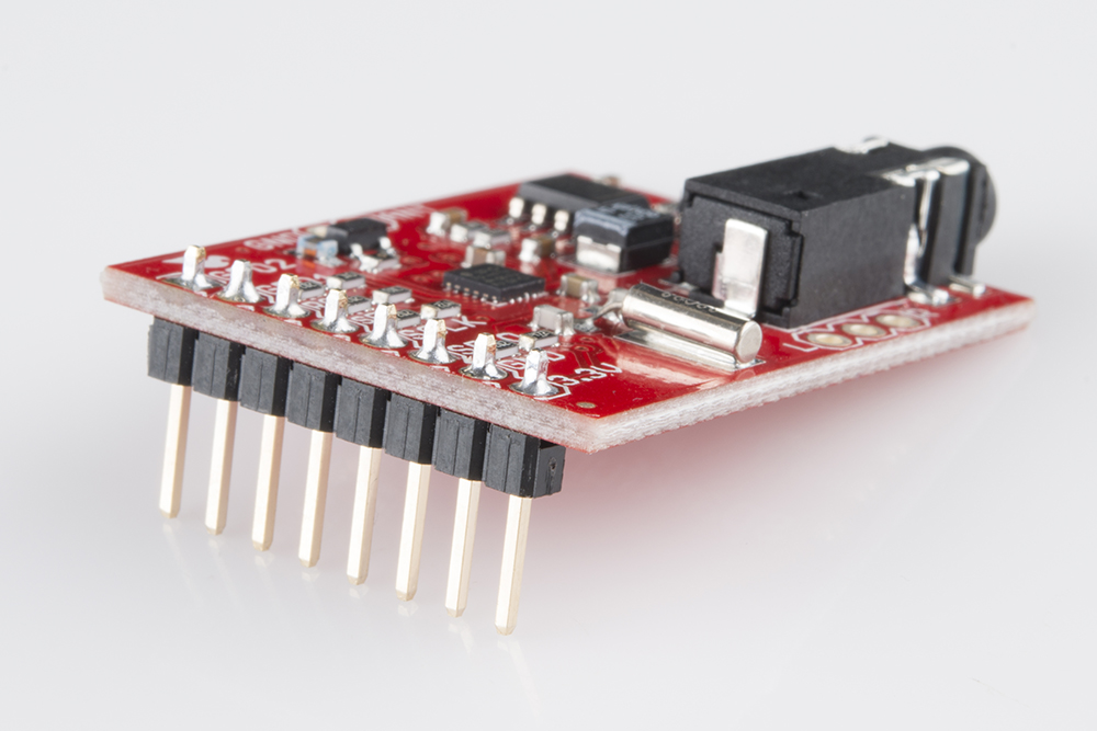
After soldering some headers into the breakout board, it should look a little something like this:
Connecting to the Arduino
We'll be using the Si4707's I2C interface for communication between the Arduino and Si4707. This interface requires connecting to the SDIO and SCLK pins to send data and a clock signal, respectively. Having control over the Si4707's reset pin (RST) is also helpful. Aside from that, all we need is 3.3V and ground. Here's a schematic:
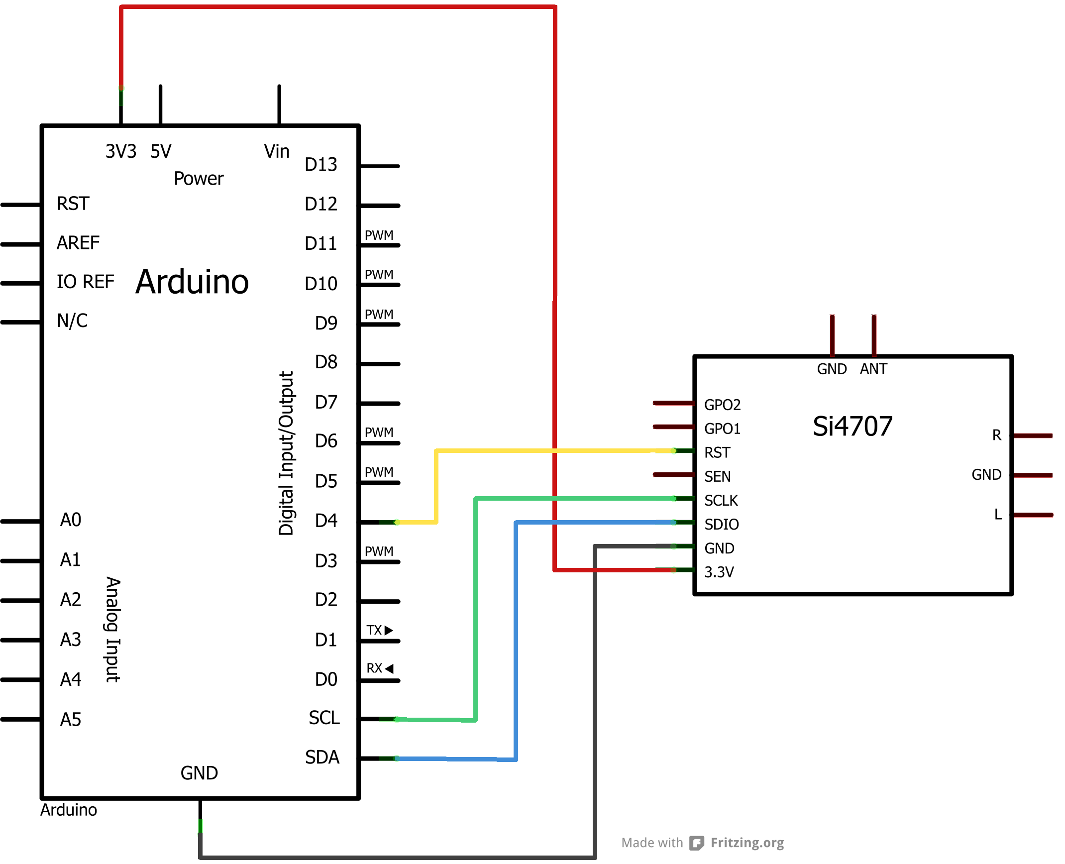
Or, for the more visually inclined, a Fritzing diagram:

The SDA and SCL pins should be present on most Arduinos. Older, pre-rev3 Arduinos might not have SCL and SDA pins. In that case, connect SDIO to A4 and SCLK to A5.
Plug In Headphones/Speakers
No doubt you want to pick up what the weather radio station is putting down! The Si4707 Breakout has an on-board 3.5mm stereo jack, plug some headphones, or your favorite powered speakers, into that jack.

The breakout board comes configured to use the headphone cord as an antenna. So it helps to have headphones or speakers with about 1.5-3ft long, untangled wires.
Once the connections have been made, you can move on to programming the Arduino!