Satellite Transceiver Breakout - Swarm M138 - Hookup Guide
This Tutorial is Retired!
This tutorial has been retired; the satellite service for this product will be terminated at the end of December 2024.
Hardware Assembly
Assembling the M138 modem onto the Breakout is very easy:
- Remove the two M2.5 screws from the standoffs
- We recommend the classic SparkFun reversible mini-screw driver, MicroMod Screwdriver, or the fancier pocket screw driver set but any #00, #0, or #1 Phillip's head driver will work.
- Align the slot of the modem's mPCIe connection with the key of the Breakout connector
- Insert the modem at an angle into the connector
- The modem will stick up at a shallow angle
- Gently hold the modem down and secure with the two M2.5 screws
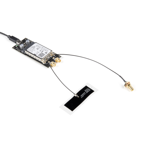
You can connect the Swarm and GNSS antennas directly to the modem:
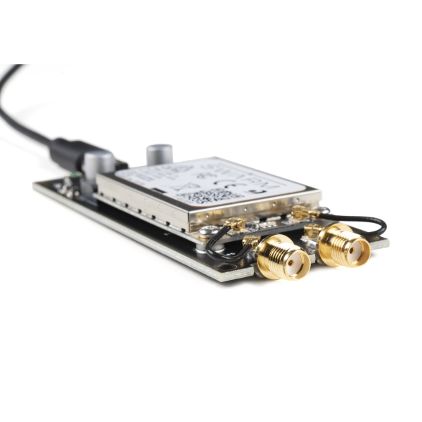
Or you may prefer to use the supplied u.FL cables to connect via the robust SMA connectors:
Either way, you may find it useful to read this tutorial first:
Three Quick Tips About Using U.FL
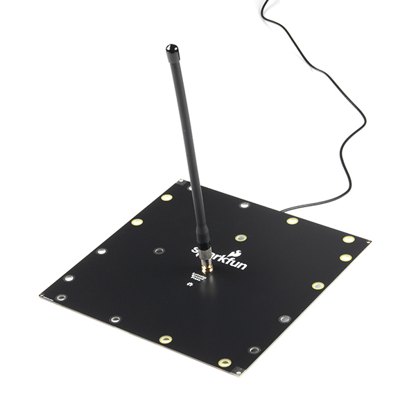
The Swarm antenna requires a ground plane for correct operation. That's why we included one in the box! Pass the female SMA connector through the hole in the ground plane and secure with the shakeproof washer and nut. Screw the Swarm antenna on top.
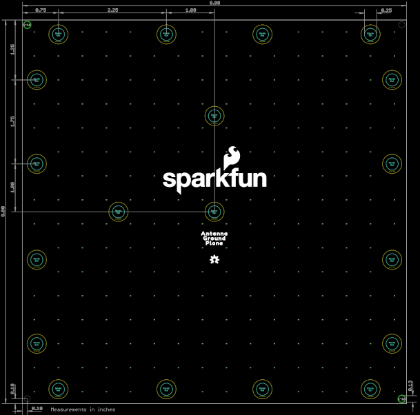
The ground plane has both grounded holes (holes with exposed tinned copper surround and through-hole plate) and plain through-holes (isolated). This allows you to connect the ground plane to any surrounding metalwork, or not, depending on your needs.
For best results, place the VHF antenna and ground plane at least 1m above the ground, or any solid surfaces.
The exposed finish is standard lead-free Hot Air Solder Levelled (HASL) plating. It will tarnish over time. You may wish to lacquer the board, with standard automotive spray lacquer, for longevity.
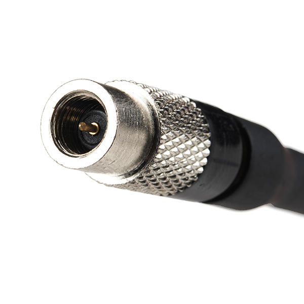
If you are using your own cables, check the SMA connector polarity. The Swarm antenna is standard polarity, not "RP" (Reverse Polarity):
