RETIRED - Raspberry gPIo
This Tutorial is Retired!
This tutorial covers concepts or technologies that are no longer current. It's still here for you to read and enjoy, but may not be as useful as our newest tutorials.
View the updated tutorial: Raspberry gPIo
Introduction
The Raspberry Pi is unique in the world of embedded electronics. Relative to its size, it's a powerhorse of a computer -- it can drive HDMI displays, process mouse, keyboard, and camera inputs, connect to the Internet, and run full-featured Linux distributions. But it's more than just a small computer, it's a hardware prototyping tool! The Pi has 17 bi-directional I/O pins, which you can use to drive LEDs, spin motors, or read button presses.
Driving the Raspberry Pi's I/O lines requires a bit of programming. Programming in what language? Take your pick! A quick glance at the Raspberry Pi GPIO examples shows that there are dozens of programming-language-choices. We've pared that list down, and ended up with two really solid, easy tools for driving I/O: Python and C (using the WiringPi library).
If you've never driven an LED or read in a button press using the Raspberry Pi, this tutorial should help to get you started. Whether you're a fan of the easily-readable, interpretive scripting language Python or more of a die-hard C programmer, you'll find a programming option that suits our needs.
Covered In This Tutorial
In this tutorial we'll show two different approaches to reading and driving the Raspberry Pi's GPIO pins: python and C. Here's a quick overview of what's covered:
- GPIO Pinout -- An overview of the Pi's 26-pin GPIO header.
- Python API and Examples
- RPi.GPIO API -- An overview of the Python functions you can use to drive GPIO.
- RPi.GPIO Example -- An example Python script that shows off both input and output functionality.
- C (and WiringPi) API and Examples
- WiringPi Setup and Test -- How to install WiringPi and then take it for a test drive on the command line.
- WiringPi API -- An overview of the basic functions provided by the WiringPi library.
- WiringPi Example -- A simple example program that shows off WiringPi's input and output capabilities.
- Using an IDE -- How to download and install Geany. Our favorite IDE for programming on the Raspberry Pi.
Each programming language has it's share of pros and cons. Python is easy (especially if your a programming novice) and doesn't require any compilation. C is faster and may be easier for those familiar with the old standby.
What You'll Need
Here's a wishlist-full of everything we used for this tutorial.
Some further notes on that bill of materials:
- Your Raspberry Pi should have an SD card with Raspbian installed on it. Check out our How to Install Raspbian tutorial for help with that.
- We're also assuming you have the necessary mouse, keyboard and display hooked up to your Pi.
- Your Pi will need an Internet connection to download WiringPi. You can use either Ethernet or WiFi (check out our Raspberry Pi WiFi tutorial for help with that.
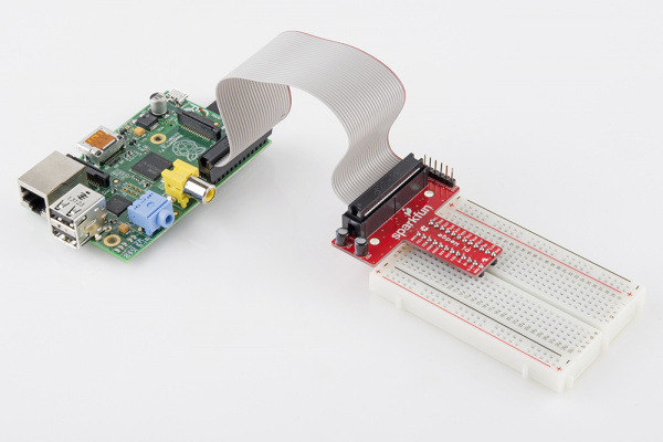
- The Pi Wedge isn't quite required, but it does make life a lot easier. If you want to skip the breakout, you can instead use Male-to-Female jumpers to connect from Pi to breadboard.
- Of course, feel free to swap in your preferred button and LEDs.
Suggested Reading
This tutorial will assume you have Raspbian installed on your Raspberry Pi. Raspbian is the most popular, well-supported Linux distribution available for the Pi. If you don't have Raspbian set up, check out our Setting Up Raspbian tutorial before continuing down this rabbit hole.
Other, more general purpose tutorials you might be interested in reading include:
- Pulse-Width Modulation -- You can use PWM to dim LEDs or send signals to servo motors. The RPi has a single PWM-capable pin.
- Light-Emitting Diodes (LEDs) -- To test the output capabilities of the Pi, we'll be driving a lot of LEDs.
- Switch Basics -- And to test inputs to the Pi, we'll be using buttons and switches.
- Pull-Up Resistors -- The Pi has internal pull-up (and pull-down) resistors. These are very handy when you're interfacing buttons with the little computer.
Suggested Viewing
Check out our Raspberry Pi video tutorials if you want a more visual introduction to the Pi!
GPIO Pinout
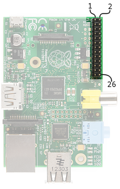
The majority of I/O pins on the Raspberry Pi exist on the 26-pin header labeled "P1". It's over in the corner of the board, adjacent to the composite video connector.
If you're coming to the Raspberry Pi as an Arduino user, you're probably used to referencing pins with a single, unique number. Programming the Pi's hardware works much the same, each pin has its own number...and then some.
There are (at least) two, different numbering schemes you may encounter when referencing Pi pin numbers: (1) Broadcom chip-specific pin numbers and (2) P1 physical pin numbers. You're usually free to use either number-system, but many programs require that you declare which scheme you're using at the very beginning of your program.
Here's a table showing all 26 pins on the P1 header, including any special function they may have, and their dual numbers:
| Broadcom Pin | Function | P1 Pin | P1 Pin | Function | Broadcom Pin | |
|---|---|---|---|---|---|---|
| 3.3V | 1 | 2 | 5V | |||
| 2 | SDA | 3 | 4 | 5V | ||
| 3 | SCL | 5 | 6 | GND | ||
| 4 | 7 | 8 | TX | 14 | ||
| GND | 9 | 10 | RX | 15 | ||
| 17 | 11 | 12 | PWM | 18 | ||
| 27 | 13 | 14 | GND | |||
| 22 | 15 | 16 | 23 | |||
| 3.3V | 17 | 18 | 24 | |||
| 10 | MOSI | 19 | 20 | GND | ||
| 9 | MISO | 21 | 22 | 25 | ||
| 11 | SCLK | 23 | 24 | CE0 | 8 | |
| GND | 25 | 26 | CE1 | 7 |
| Legend: | 5V | 3.3V | GND | I2C | SPI | PWM |
|---|
Note: The Broadcom pin numbers above relate to Rev2 of the Raspberry Pi only. If you have an older Rev1 Pi, check out this link for your Broadcom pin numbers.
As you can see, the Pi not only gives you access to 17 bi-directional I/O pins, but also Serial (UART), I2C, SPI, and even some PWM ("analog output").
Hardware Setup
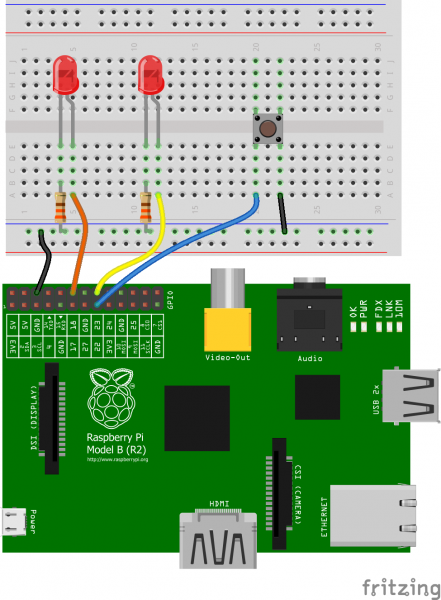
To get a head start you can assemble the circuit now. We'll use this setup for both the C and Python examples. We'll use two LEDs to test the output functionality (digital and PWM), and a button to test the input.
Our two LEDs are connected to the Pi's pins 18 and 23 -- those are the Broadcom chip-specific numbers. If you're basing your wiring off the P1 connector pin numbers, that'd be pins 12 and 16.
The button is connected to Broadcom pin 22, aka P1 pin 15.
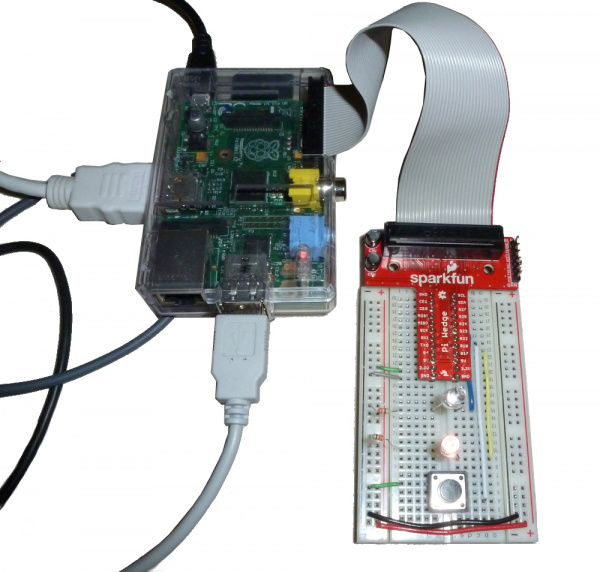
If you have Pi Wedge, the hookup should be pretty straight-forward. It'll look a little something like this when you're done:
If you don't have a Pi Wedge, male-to-female jumper wires help to make an easy transition from Pi to breadboard.
Python (RPi.GPIO) API
We'll use the RPi.GPIO module as the driving force behind our Python examples. This set of Python files and source is included with Raspbian, so assuming you're running that most popular Linux distribution, you don't need to download anything to get started.
On this page we'll provide an overview of the basic function calls you can make using this module.
Setup Stuff
In order to us RPi.GPIO throughout the rest of your Python script, you need to put this statement at the top of your file:
language:Python
import RPi.GPIO as GPIO
That statement "includes" the RPi.GPIO module, and goes a step further by providing a local name -- GPIO -- which we'll call to reference the module from here on.
Pin Numbering Declaration
After you've included the RPi.GPIO module, the next step is to determine which of the two pin-numbering schemes you want to use:
GPIO.BOARD-- Board numbering scheme. The pin numbers follow the pin numbers on header P1.GPIO.BCM-- Broadcom chip-specific pin numbers. These pin numbers follow the lower-level numbering system defined by the Raspberry Pi's Broadcom-chip brain.
If you're using the Pi Wedge, we recommend using the GPIO.BCM definition -- those are the numbers silkscreened on the PCB. The GPIO.BOARD may be easier if you're wiring directly to the header.
To specify in your code which number-system is being used, use the GPIO.setmode() function. For example...
language:Python
GPIO.setmode(GPIO.BCM)
...will activate the Broadcom-chip specific pin numbers.
Both the import and setmode lines of code are required, if you want to use Python.
Setting a Pin Mode
If you've used Arduino, you're probably familiar with the fact that you have to declare a "pin mode" before you can use it as either an input or output. To set a pin mode, use the setup([pin], [GPIO.IN, GPIO.OUT] function. So, if you want to set pin 18 as an output, for example, write:
language:Python
GPIO.setup(18, GPIO.OUT)
Remember that the pin number will change if you're using the board numbering system (instead of 18, it'd be 12).
Outputs
Digital Output
To write a pin high or low, use the GPIO.output([pin], [GPIO.LOW, GPIO.HIGH]) function. For example, if you want to set pin 18 high, write:
language:Python
GPIO.output(18, GPIO.HIGH)
Writing a pin to GPIO.HIGH will drive it to 3.3V, and GPIO.LOW will set it to 0V. For the lazy, alternative to GPIO.HIGH and GPIO.LOW, you can use either 1, True, 0 or False to set a pin value.
PWM ("Analog") Output
PWM on the Raspberry Pi is about as limited as can be -- one, single pin is capable of it: 18 (i.e. board pin 12).
To initialize PWM, use GPIO.PWM([pin], [frequency]) function. To make the rest of your script-writing easier you can assign that instance to a variable. Then use pwm.start([duty cycle]) function to set an initial value. For example...
language:Python
pwm = GPIO.PWM(18, 1000)
pwm.start(50)
...will set our PWM pin up with a frequency of 1kHz, and set that output to a 50% duty cycle.
To adjust the value of the PWM output, use the pwm.ChangeDutyCycle([duty cycle]) function. [duty cycle] can be any value between 0 (i.e 0%/LOW) and 100 (ie.e 100%/HIGH). So to set a pin to 75% on, for example, you could write:
language:Python
pwm.ChangeDutyCycle(75)
To turn PWM on that pin off, use the pwm.stop() command.
Simple enough! Just don't forget to set the pin as an output before you use it for PWM.
Inputs
If a pin is configured as an input, you can use the GPIO.input([pin]) function to read its value. The input() function will return either a True or False indicating whether the pin is HIGH or LOW. You can use an if statement to test this, for example...
language:Python
if GPIO.input(22):
    print("Pin 2 is HIGH")
else:
    print("Pin 2 is LOW")
...will read pin 22 and print whether it's being read as HIGH or LOW.
Pull-Up/Down Resistors
Remember back to the GPIO.setup() function where we declared whether a pin was an input or output? There's an optional third parameter to that function, which you can use to set pull-up or pull-down resistors. To use a pull-up resistor on a pin, add pull_up_down=GPIO.PUD_UP as a third parameter in GPIO.setup. Or, if you need a pull-down resistor, instead use pull_up_down=GPIO.PUD_DOWN.
For example, to use a pull-up resistor on pin 22, write this into your setup:
language:Python
GPIO.setup(22, GPIO.IN, pull_up_down=GPIO.PUD_UP)
If nothing is declared in that third value, both pull-resistors will be disabled.
Etc.
Delays
If you need to slow your Python script down, you can add delays. To incorporate delays into your script, you'll need to include another module: time. This line, at the top of your script, will do it for you:
language:Python
include time
Then, throughout the rest of your script, you can use time.sleep([seconds]) to give your script a rest. You can use decimals to precisely set your delay. For example, to delay 250 milliseconds, write:
language:Python
time.sleep(0.25)
The time module includes all sorts of useful functions, on top of sleep. Check out the reference here.
Garbage Collecting
Once your script has run its course, be kind to the next process that might use your GPIOs by cleaning up after yourself. Use the GPIO.cleanup() command at the end of your script to release any resources your script may be using.
Your Pi will survive if you forget to add this command, but it is good practice to include wherever you can.
Now then. Lets incorporate everything we learned here into an example script to try everything out.
Python (RPi.GPIO) Example
Follow along as we use the basic RPi.GPIO functions from the last page to create a simple example GPIO script.
1. Create a File
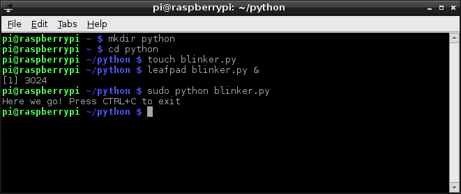
To begin, we need to create a Python file. You can do this through the GUI-based file explorer. Or, if you want a terminal-based solution, open up LXTerminal, and navigate to a folder you'd like the file to live (or create one). And create a new folder with these commands:
pi@raspberrypi ~/code $ mkdir python
pi@raspberrypi ~/code $ cd python
Create a file -- we'll call ours "blinker" -- and terminate it with a .py extension. Then open it up in your favorite text editor. Nano works, as does Pi's default GUI text editor, Leafpad.
pi@raspberrypi ~/code/python $ touch blinker.py
pi@raspberrypi ~/code/python $ leafpad blinker.py &
That'll open up a blank text file (the "&" will open it in the background, leaving the terminal in place for future use). Time for some code!
2. Codify
Here's an example sketch that incorporates everything we learned on the last page. It does a little input and output, and even handles some PWM. This assumes you've set up the circuit as arranged on the Hardware Setup page.
language:Python
# External module imports
import RPi.GPIO as GPIO
import time

# Pin Definitons:
pwmPin = 18 # Broadcom pin 18 (P1 pin 12)
ledPin = 23 # Broadcom pin 23 (P1 pin 16)
butPin = 22 # Broadcom pin 22 (P1 pin 15)

dc = 95 # duty cycle (0-100) for PWM pin

# Pin Setup:
GPIO.setmode(GPIO.BCM) # Broadcom pin-numbering scheme
GPIO.setup(ledPin, GPIO.OUT) # LED pin set as output
GPIO.setup(pwmPin, GPIO.OUT) # PWM pin set as output
pwm = GPIO.PWM(pwmPin, 50)  # Initialize PWM on pwmPin 100Hz frequency
GPIO.setup(butPin, GPIO.IN, pull_up_down=GPIO.PUD_UP) # Button pin set as input w/ pull-up

# Initial state for LEDs:
GPIO.output(ledPin, GPIO.LOW)
pwm.start(dc)

print("Here we go! Press CTRL+C to exit")
try:
    while 1:
        if GPIO.input(butPin): # button is released
            pwm.ChangeDutyCycle(dc)
            GPIO.output(ledPin, GPIO.LOW)
        else: # button is pressed:
            pwm.ChangeDutyCycle(100-dc)
            GPIO.output(ledPin, GPIO.HIGH)
            time.sleep(0.075)
            GPIO.output(ledPin, GPIO.LOW)
            time.sleep(0.075)
except KeyboardInterrupt: # If CTRL+C is pressed, exit cleanly:
    pwm.stop() # stop PWM
    GPIO.cleanup() # cleanup all GPIO
After you've typed all of that in (don't forget your whitespace!) save.
Running the Script
The RPi.GPIO module requires administrator privileges, so you'll need to tag a sudo on to the front of your Python script call. To run your "blinker.py" script, type:
pi@raspberrypi ~/code/python $ sudo python blinker.py
With the code running, press the button to turn on the digital LED. The PWM-ing LED will invert its brightness when you press the button as well.
Press CTRL+C to cleanly exit the script.
C (WiringPi) Setup
Python is a great GPIO-driving option, especially if you're used to it. But if you're a rickety old programmer, unfamiliar with the whitespace-driven scripting language, and would rather live within the happy confines of C, then let me introduce the WiringPi library.
1) Install Wiring Pi
git://git.drogon.net/wiringPi" is not available.
Wiring Pi is previously not included with early versions of Raspbian. This required users to download and install it. Luckily, Wiring Pi is included in standard Raspbian systems. If you are looking to update using a mirrored Wiring Pi with small updates to support newer hardware, we recommend checking out this GitHub repository.
You'll need git (may be installed by default). If git is not installed, enter the following into the command line.
pi@raspberrypi ~/code $ sudo apt-get install git-core
We highly recommend using Git to download the latest version. To check what version you have, enter the following command.
pi@raspberrypi ~/code $ gpio -v
If you receive an output similar to to the following with the Unknown17, you'll want to update WiringPi on a Raspberry Pi 4 or above.
language:bash
gpio version: 2.50
Copyright (c) 2012-2018 Gordon Henderson
This is free software with ABSOLUTELY NO WARRANTY.
For details type: gpio -warranty

Raspberry Pi Details:
  Type: Unknown17, Revision: 02, Memory: 0MB, Maker: Sony
    * Device tree is enabled.
    * --> Raspberry Pi 4 Model B Rev 1.2
    * This Raspberry Pi supports user-level GPIO access.
Enter the following to remove the wiringPi and configuration files. Then use the hash command for the Pi to remove all locations that remember wiringPi.
pi@raspberrypi ~/code $ sudo apt-get purge wiringpi
pi@raspberrypi ~/code $ hash -r
As long as you have Git installed, these commands should be all you need to download and install Wiring Pi:
pi@raspberrypi ~/code $ git clone https://github.com/WiringPi/WiringPi.git
pi@raspberrypi ~/code $ cd WiringPi
pi@raspberrypi ~/code/WiringPi $ git pull origin
pi@raspberrypi ~/code/WiringPi $ ./build
2) Test Wiring Pi
WiringPi is awesome because it's actually more than just a C library, it includes a command-line utility as well! You can test your installation of WiringPi with the gpio utility.
Open up a terminal, and try some of these system calls:
pi@raspberrypi ~/code $ gpio -g mode 18 output
pi@raspberrypi ~/code $ gpio -g write 18 1
pi@raspberrypi ~/code $ gpio -g write 18 0
As long as your LED is still connected to pin 18 it should blink on and off following the last two commands.
Or, to test the button, type:
pi@raspberrypi ~/code $ gpio -g mode 22 up
pi@raspberrypi ~/code $ gpio -g read 22
Either 0 or 1 will be returned, depending on whether the button is pressed or not. Try typing that last line again while pressing the button.
The gpio utility, as stated in the manual, is a "swiss army knife" command-line tool. We highly recommend checking out the man page (type man gpio) to discover everything it can do.
If you're ready to get on with some C-style programming, head over to the next page. We'll overview some of the most useful functions provided by the WiringPi library.
C (WiringPi) API
On this page we'll discuss some of the most useful functions provided by the WiringPi library. It's tailored to look a lot like Arduino, so if you've done any Arduino programming some of this may look familiar.
Setup Stuff
To begin, you'll need to include the library. At the beginning of your program, type:
language:c
#include <wiringPi.h>
After you've included the library, your first steps should be to initialize it. This step also determines which pin numbering scheme you'll be using throughout the rest of your program. Pick one of these function calls to initialize the library:
language:c
wiringPiSetup(); // Initializes wiringPi using wiringPi's simlified number system.
wiringPiSetupGpio(); // Initializes wiringPi using the Broadcom GPIO pin numbers
WiringPi's simplified number system introduces a third pin-numbering scheme. We didn't show it in the table earlier, if you want to use this scheme, check out their pins page for an overview.
Pin Mode Declaration
To set a pin as either an input or output, use the pinMode([pin], [mode]) function. Mode can be either INPUT, OUTPUT, or PWM_OUTPUT.
For example, to set pin 22 as an input, 23 as an output, and 18 as a PWM, write:
language:c
wiringPiSetupGpio()
pinMode(22, INPUT);
pinMode(23, OUTPUT);
pinMode(18, PWM_OUTPUT);
Keep in mind that the above example uses the Broadcom GPIO pin-numbering scheme.
Digital Output
The digitalWrite([pin], [HIGH/LOW]) function can be used to set an output pin either HIGH or LOW. Easy enough, if you're an Arduino user.
To set pin 23 as HIGH, for example, simply call:
language:c
digitalWrite(23, HIGH);
PWM ("Analog") Output
For the lone PWM pin, you can use pwmWrite([pin], [0-1023]) to set it to a value between 0 and 1024. As an example...
language:c
pwmWrite(18, 723);
...will set pin 18 to a duty cycle around 70%.
Digital Input
If you're an Arduino veteran, you probably know what comes next. To read the digital state of a pin, digitalRead([pin]) is your function. For example...
language:c
if (digitalRead(22))
    printf("Pin 22 is HIGH\n");
else
    printf("Pin 22 is LOW\n");
...will print the status of pin 22. The digitalRead() function returns 1 if the pin is HIGH and 0 if it's LOW.
Pull-Up/Down Resistors
Need some pull-up or pull-down resistors on your digital input? Use the pullUpDnControl([pin], [PUD_OFF, PUD_DOWN, PUD_UP]) function to pull your pin.
For example, if you have a button on pin 22 and need some help pulling it up, write:
language:c
pullUpDnControl(22, PUD_UP);
That comes in handy if your button pulls low when it's pressed.
Delays
Slowing down those blinking LEDs is always useful -- assuming you actually want to differentiate between on and off. WiringPi includes two delay functions to choose from: delay([milliseconds]) and delayMicroseconds([microseconds]).
The standard delay will halt the program flow for a specified number of milliseconds. If you want to delay for 2 seconds, for example, write:
language:c
delay(2000);
Or you can use delayMicroseconds() to get a more precise, microsecond-level delay.
Now that you know the basics, let's apply them to an example piece of code.
C (WiringPi) Example
The intention of WiringPi is to make your I/O code look as Arduino-ified as possible. However keep in mind that we're no longer existing in the comfy confines of Arduino -- there's no loop() or setup(), just int main(void).
Follow along here as we create an example C file, incorporate the WiringPi library, and compile and run that program.
Create blinker.c
Using the terminal, navigate to a folder of your choice and create a new file -- "blinker.c". Then open that file in a text editor (Nano or Leafpad are included with Raspbian).
pi@raspberrypi ~/code $ mkdir c_example
pi@raspberrypi ~/code $ cd c_example
pi@raspberrypi ~/code/c_example $ touch blinker.c
pi@raspberrypi ~/code/c_example $ leafpad blinker.c &
The commands above will open your "blinker.c" file in Leafpad, while leaving your terminal functioning -- in-directory -- in the background.
Program!
Here's an example program that includes a little bit of everything we talked about on the last page. Copy and paste, or write it yourself to get some extra reinforcement.
language:c
#include <stdio.h>    // Used for printf() statements
#include <wiringPi.h> // Include WiringPi library!

// Pin number declarations. We're using the Broadcom chip pin numbers.
const int pwmPin = 18; // PWM LED - Broadcom pin 18, P1 pin 12
const int ledPin = 23; // Regular LED - Broadcom pin 23, P1 pin 16
const int butPin = 22; // Active-low button - Broadcom pin 22, P1 pin 15

const int pwmValue = 75; // Use this to set an LED brightness

int main(void)
{
    // Setup stuff:
    wiringPiSetupGpio(); // Initialize wiringPi -- using Broadcom pin numbers

    pinMode(pwmPin, PWM_OUTPUT); // Set PWM LED as PWM output
    pinMode(ledPin, OUTPUT);     // Set regular LED as output
    pinMode(butPin, INPUT);      // Set button as INPUT
    pullUpDnControl(butPin, PUD_UP); // Enable pull-up resistor on button

    printf("blinker is running! Press CTRL+C to quit.");

    // Loop (while(1)):
    while(1)
    {
        if (digitalRead(butPin)) // Button is released if this returns 1
        {
            pwmWrite(pwmPin, pwmValue); // PWM LED at bright setting
            digitalWrite(ledPin, LOW);     // Regular LED off
        }
        else // If digitalRead returns 0, button is pressed
        {
            pwmWrite(pwmPin, 1024 - pwmValue); // PWM LED at dim setting
            // Do some blinking on the ledPin:
            digitalWrite(ledPin, HIGH); // Turn LED ON
            delay(75); // Wait 75ms
            digitalWrite(ledPin, LOW); // Turn LED OFF
            delay(75); // Wait 75ms again
        }
    }

    return 0;
}
Once you've finished, Save and return to your terminal.
Compile and Execute!
Unlike Python, which is an interpreted language, before we can run our C program, we need to build it.
To compile our program, we'll invoke gcc. Enter this into your terminal, and wait a second for it to finish compiling:
pi@raspberrypi ~/code/c_example $ gcc -o blinker blinker.c -l wiringPi
That command will create an executable file -- "blinker". The "-l wiringPi" part is important, it loads the wiringPi library. A successful compilation won't produce any messages; if you got any errors, try to use the messages to track them down.
Type this to execute your program:
pi@raspberrypi ~/code/c_example $ sudo ./blinker
The blinker program should begin doing it's thing. Make sure you've set up the circuit just as modeled on the hardware setup page. Press the button to blink the LED, release to have it turn off. The PWM-ing LED will be brightest when the button is released, and dim when the button is pressed.
If typing all of that code in a bland, black-and-white, non-highlighting editor hurt your brain, check out the next page where we introduce a simple IDE that makes your programming more efficient.
Using an IDE!
Thus far we've been using simple text-editors -- Leafpad or Nano -- to write our Python and C programs. So seasoned programmers are probably missing a whole lot of features assumed of even the most basic editors: auto-tabbing, context-highlighting, even automated building. If you want to incorporate any of those features, we recommend using an IDE (integrated development environment). One of our favorite Pi IDE's is Geany, here's how to get it up and running.
Download and Install Geany
Geany isn't included with Raspbian, so you'll need an Internet connection to download it. You can use the magical apt-get utility to install it with this command:
pi@raspberrypi ~/code $ sudo apt-get update
pi@raspberrypi ~/code $ sudo apt-get install geany
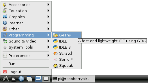
Once installed, you can run Geany by going to the "Start" menu, and looking under the "Programming" tab.
Or, from the terminal, you can type sudo geany. You can even open a file in Geany, directly from the command line. To open our previous C file, for example, type sudo geany blinker.c.
Using Geany...
Once Geany is running, you can create a new file by going to File > New. Saving the file as either ".c" or ".py" (or any other common language file extension) will immediately inform Geany what kind of language you're working with, so it can start highlighting your text.
Geany can be used with most languages, including the Python and C examples we've just examined. Some tweaks to the default IDE options are necessary, though. Here's an overview of using Geany with each language.
...with C and WiringPi
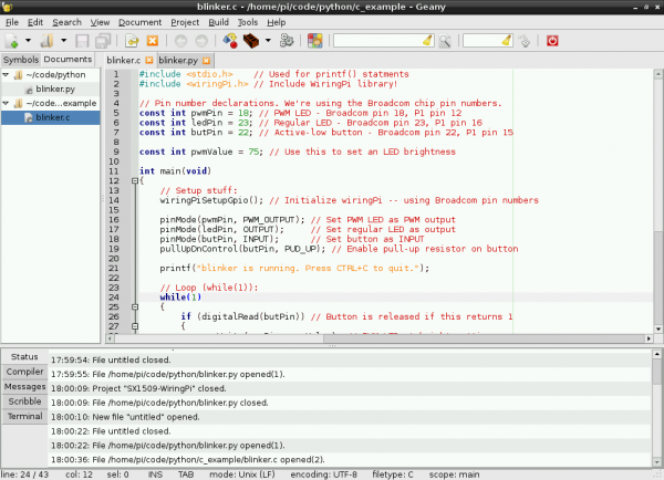
Let's recreate our WiringPi Example with Geany. Open the "blinker.c" created earlier within the confines of Geany. You should immediately be presented with some very pleasant color-coding.
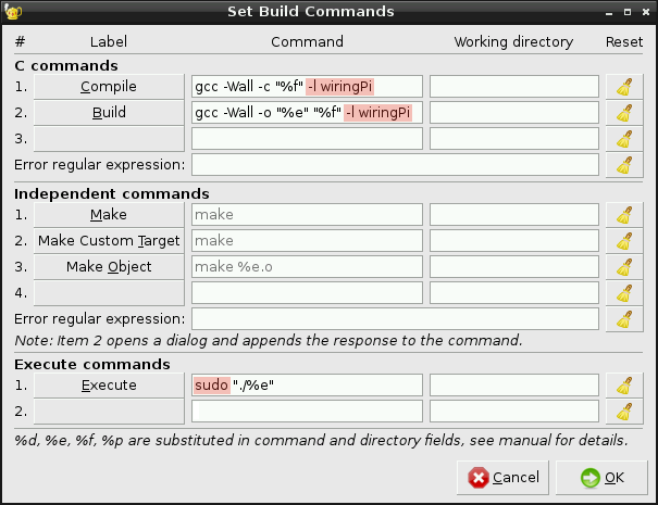
Before trying to compile the code, though, you'll need to tweak some of the build options. Go up to Build and Set Build Commands. Inside the "Compile" and "Build" text blocks, tack this on to the end of the default command: -l wiringPi. That will load the wiringPi library.
While you're here, add "sudo" to the beginning of your execute command. Make sure your build commands look like the window above and click "OK".
Once you've adjusted that setting, you should be ready to go. Click the Build menu, then click Build (or click the red cinder-block-looking icon up top). Upon building, the IDE will switch focus to the bottom "Compiler" tab, and relay the results of your compilation. If the build was successful, go ahead and run with it.
To run your built file, click Build > Execute (or click the gear icon up top). Executing will bring up a new terminal window, and start your program running. You can stop the program by pressing CTRL+C in the terminal window.
...with Python
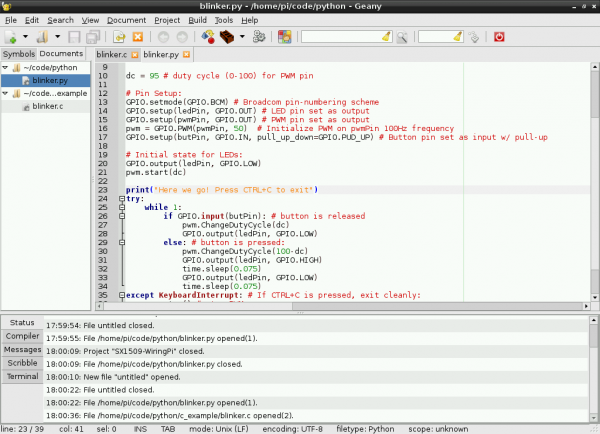
You can also use Geany with Python. To test it out, go ahead an open up the "blinker.py" file we created earlier. As with the C file, you'll be greeted with some pleasnt context highlighting.
No building required with Python! Once you're script is written, simply click the "Execute" gear up top. Again, running will produce a separate terminal to pop up. To exit, simply press CTRL+C.
Geany has tons of features beyond what we've covered here. Check out the tabs at the bottom. Check out the menus up top. Experiment and see how the IDE can make your programming life easier!
Resources and Going Further
Now that you know how to blink your Pi's LEDs, check out some of these resources for going further:
- RPi Low-level peripherals -- A Wiki with tons of details on using the Raspberry Pi's GPIO peripherals.
- WiringPi Hompeage -- The home of WiringPi and a variety of other Raspberry-Pi-related tools. Check it out!
- RPi.GPIO Homepage -- Home of the Raspberry Pi GPIO python module. Great source for API and documentation.
If you're looking for some project inspiration, here are some more SparkFun tutorials where you'll be able to leverage your newfound Pi programming skills:
- Raspberry Pi Twitter Monitor -- How to use a Raspberry Pi to monitor Twitter for hashtags and blink an LED.
- Getting Started with the BrickPi -- How to connect your Raspberry Pi to Mindstorms, using the BrickPi.
- pcDuino 2 Hookup Guide -- An introduction to the pcDuino -- an equally (if not more) powerful single board computer.
