RedBot Assembly Guide
This Tutorial is Retired!
This tutorial covers concepts or technologies that are no longer current. It's still here for you to read and enjoy, but may not be as useful as our newest tutorials.
 SFUptownMaker,
  HelloTechie
**Adding the Bumpers**
In this section, you will need to screw the Mechanical Bumpers into place on the front end of your RedBot chassis.
Locate the following:
- 2x 4-40 1/4" Phillips Screw
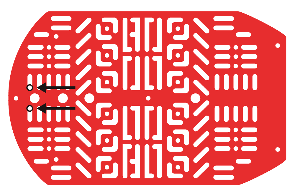
Locate the two positions on the top chassis piece.
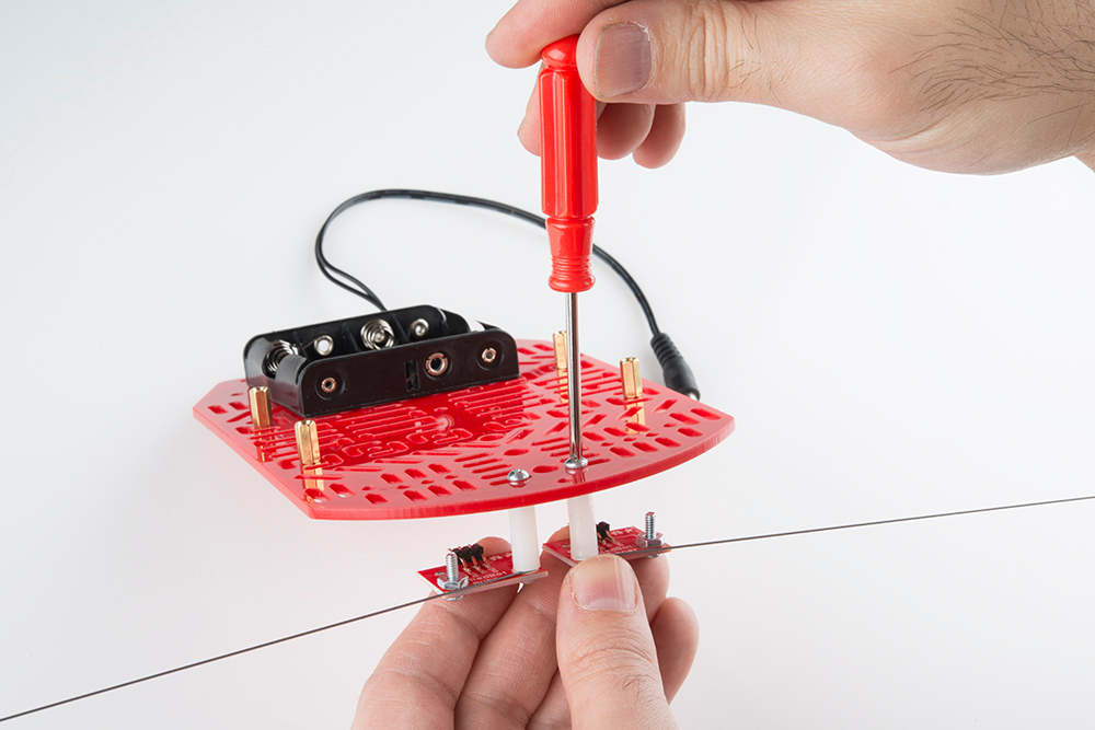
Using two 4-40 1/4" screws, tighten down the Mechanical Bumpers, with the two wires pointing in opposite directions, on the bottom side of the top chassis piece. The Mechanical Bumpers' header pins should be pointing towards the chassis piece.
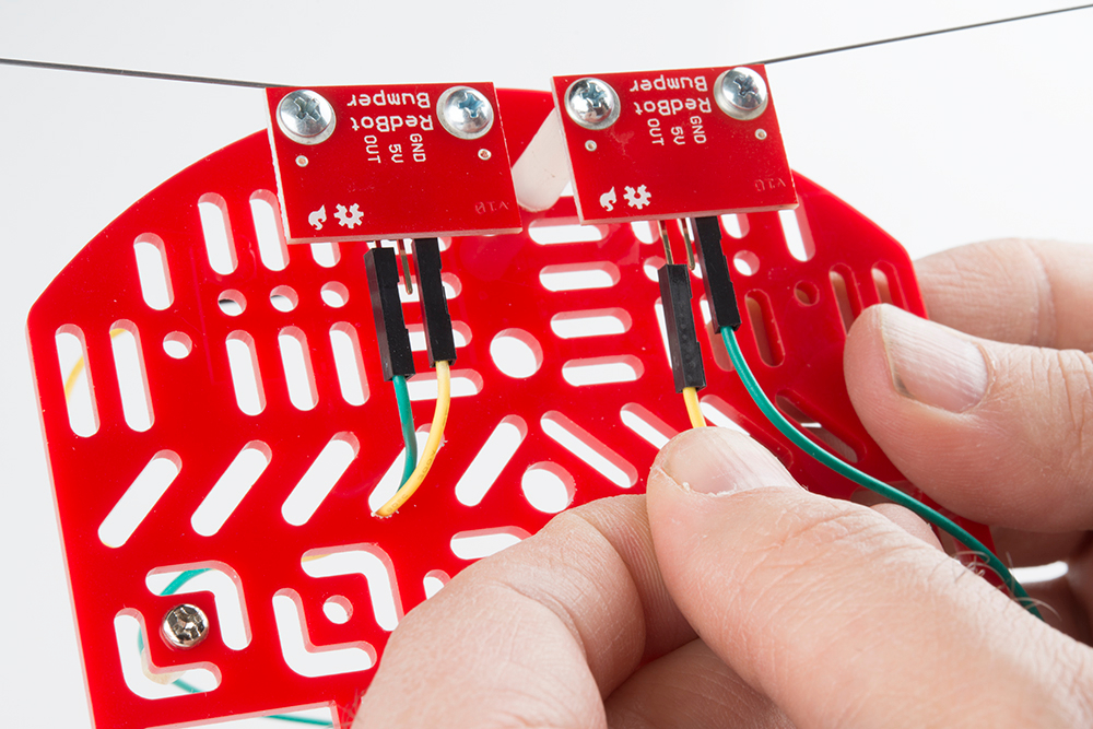
Add jumper wires to the GND and OUT pins on both of the Mechanical Bumpers. You will not add jumper wires to the 5V pins. Again, which color jumper wires you choose does not matter, but it might be helpful to follow along with this assembly guide.
Left RedBot Sensor - Mechanical Bumper → RedBot Mainboard
- GND → Green
- OUT → Yellow
Right RedBot Sensor - Mechanical Bumper → RedBot Mainboard
- GND → Yellow
- OUT → Green
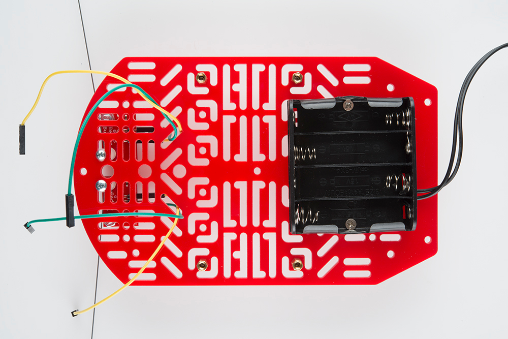
Put the other ends of the jumper wires through the top chassis piece.
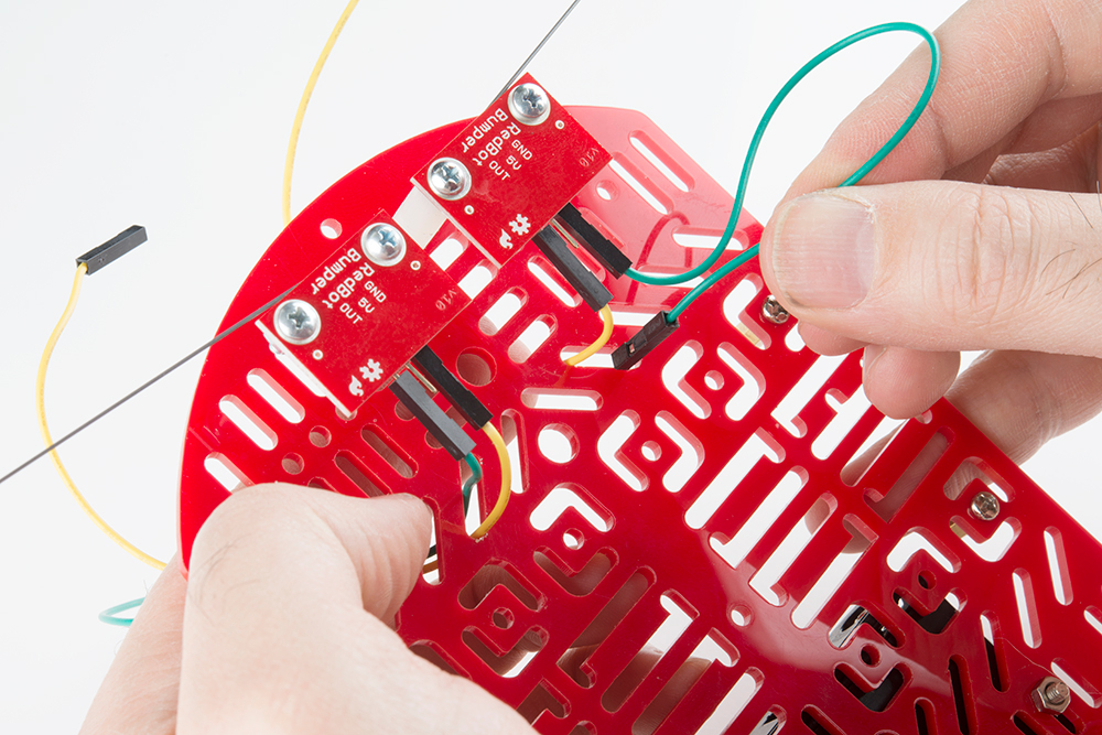
Make sure the jumper wires are all the way through.