Qwiic GRID-Eye Infrared Array (AMG88xx) Hookup Guide
Introduction
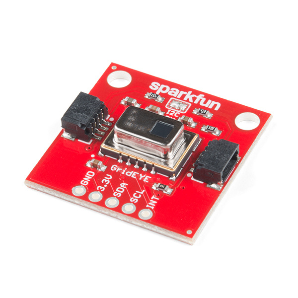
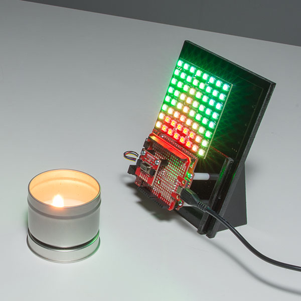
The Grid-EYE from Panasonic is an 8x8 thermopile array. This means you have a square array of 64 pixels each capable of independent temperature detection. It’s like having thermal camera (or Predator’s vision), just in really low resolution. It's part of SparkFun's Qwiic system, so it is easier to connect to get your low-resolution infrared image.
In this hookup guide, we'll connect our sensor up to our microcontroller of choice and read the array simply as 0's and 1's in an Arduino Serial Monitor. We'll also read the interrupt array to find out which pixels are detecting a value higher than a certain threshold. We'll go over how to check the temperature of the chip itself using the built in thermistor. Once we figure out how to interface with the GRID-Eye in our Arduino IDE, we'll move over to Processing to get some neat visuals from our pixel array, and actually get a nice looking thermal camera.
Required Materials
To get started, you'll need a microcontroller to control everything in your project.
Particle Photon (Headers)
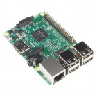
WRL-13774Raspberry Pi 3
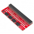
DEV-13825Now to get your microcontroller into the Qwiic ecosystem, the key will be one of the following Qwiic shields to match your preference of microcontroller:
SparkFun Qwiic Shield for Photon
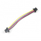
DEV-14477You will also need a Qwiic cable to connect the shield to your GRID-Eye, choose a length that suits your needs.
Qwiic Cable - 100mm
PRT-14427Qwiic Cable - 50mm
PRT-14426Qwiic Cable - 200mm
PRT-14428Qwiic Cable - 500mm
PRT-14429Suggested Reading
If you aren't familiar with our new Qwiic system, we recommend reading here for an overview. We would also recommend taking a look at the hookup guide for the Qwiic Shield if you haven't already. Brushing up on your skills in I2C is also recommended, as all Qwiic sensors are I2C. Since we'll also be using Processing in one of these demos, we'd recommend looking up the tutorial on hooking your Arduino up to Processing.
Connecting Arduino to Processing
I2C
Qwiic Shield for Arduino & Photon Hookup Guide
Hardware Overview
Let's look over a few characteristics of the Qwiic Grid-EYE so we know a bit more about how it behaves.
| Characteristic | Range |
|---|---|
| Operating Voltage(Startup) | 1.6V - 3.6V |
| Operating Voltage(Timekeeping) | 1.5V - 3.6V |
| Operating Temperature | -40°C - 85°C |
| Time Accuracy | ±2.0 ppm |
| Temperature Accuracy | ±2.5°C |
| Current Consumption | 4.5 mA |
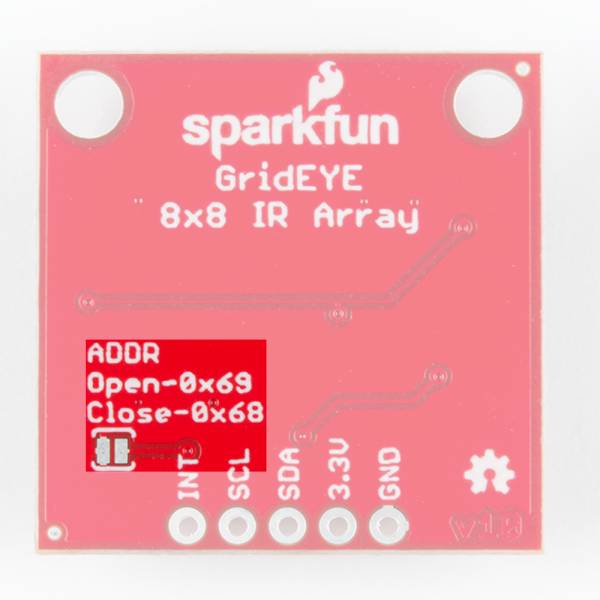
| I2C Address | 0x69 (open jumper, default) or 0x68 (closed jumper) |
Pins
The characteristics of the available pins on the Grid-EYE are outlined in the table below.
| Pin Label | Pin Function | Input/Output | Notes |
|---|---|---|---|
| 3.3V | Power Supply | Input | Should be between 1.95 - 3.6V |
| SDA | I2C Data Signal | Bi-directional | Bi-directional data line. Voltage should not exceed power supply (e.g. 3.3V). |
| SCL | I2C Clock Signal | Input | Master-controlled clock signal. Voltage should not exceed power supply (e.g. 3.3V). |
| INT | Interrupt | Output | Interrupt pin, digital output. |
| GND | Ground | Input | 0V/common voltage. |
Optional Features
Pull-Up Resistors
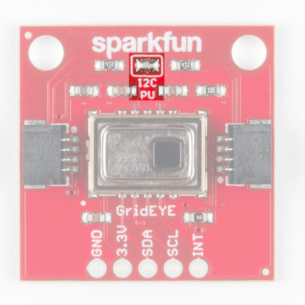
The Qwiic GRID-Eye has onboard I2C pull-up resistors; if multiple sensors are connected to the bus with the pull-up resistors enabled, the parallel equivalent resistance will create too strong of a pull-up for the bus to operate correctly. As a general rule of thumb, disable all but one pair of pull-up resistors if multiple devices are connected to the bus. If you need to disconnect the pull up resistors they can be removed by removing the solder on the corresponding jumpers highlighted below.
I2C Address
There is an additional jumper on the back of the board that allows the I2C to be changed from the default 0x69 to 0x68 if you have multiple GRID-Eye cameras on the same I2C bus. Normally open, the jumper sets the I2C address to 0x69. Closing the jumper with solder will give an I2C address of 0x68. However, if you have more than 2 GRID-Eye's, you'll need the Qwiic Mux to have them all on the same I2C bus. The jumper is highlighted below.
Hardware Assembly
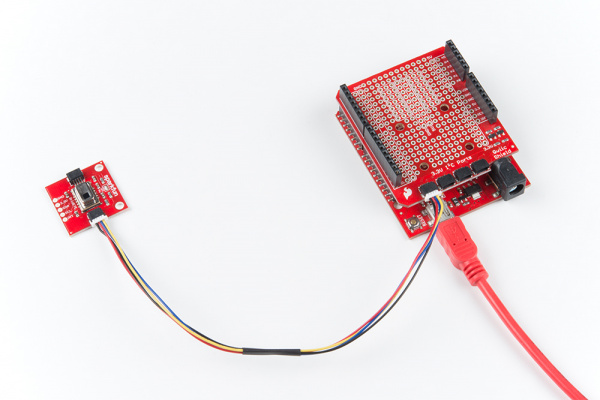
If you haven't yet assembled your Qwiic Shield, now would be the time to head on over to that tutorial. With the shield assembled, Sparkfun's new Qwiic environment means that connecting the sensor could not be easier. Just plug one end of the Qwiic cable into the GRID-Eye breakout, the other into the Qwiic Shield of your choice and you'll be ready to upload a sketch and figure out how far away you are from that thing over there. It seems like it's too easy too use, but that's why we made it that way!
Arduino Example Code
Note: This example assumes you are using the latest version of the Arduino IDE on your desktop. If this is your first time using Arduino, please review our tutorial on installing the Arduino IDE. If you have not previously installed an Arduino library, please check out our installation guide.
SparkFun has written a library to control the Qwiic GRID-Eye. You can obtain these libraries through the Arduino Library Manager. Search for SparkFun GridEYE AMG88 Library and you should be able to install the latest version. If you prefer downloading the libraries manually you can grab them from the GitHub repository:
Example 1 - Serial Visualizer
Once you've installed the Grid-EYE library, restart Arduino. Then go to File > Examples > SparkFun GridEYE AMG88 Library > Example1-SerialVisualizer to open the example sketch.
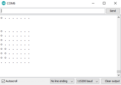
Once you've set your Board and Serial Port, upload the sketch to your Arduino. Then open the serial monitor. You'll begin to see an 8x8 array of numbers between 0 and 3. The Arduino is mapping the values in between the temperatures between HOT and COLD to values between 0 and 3, these values are then represented by a . for 0, o for 1, 0for 2, and O for 3. Try moving in front of the camera and see if any values change. Play around with the values of HOT and COLD as well to see different ranges of temperatures mapped from 0 to 3. Notice how we use the function grideye.getPixelTemperature(i) to get the temperature of pixel i, where i is between 0 and 64. With these temperatures mapped to a grid, the output should look something like the below image.
Example 2 - Using Interrupts
To pull up the next example, go to File > Examples > SparkFun GridEYE AMG88 Library > Example2-UsingInterrupts to open the example sketch.
Once you've loaded this example up to your microcontroller, go ahead and check out the void setup() loop. We set up how the Interrupts are triggered with the following code.
language:c
grideye.setInterruptModeAbsolute();
grideye.setUpperInterruptValue(UPPER_LIMIT);
grideye.setLowerInterruptValue(LOWER_LIMIT);
grideye.setInterruptHysteresis(HYSTERESIS);
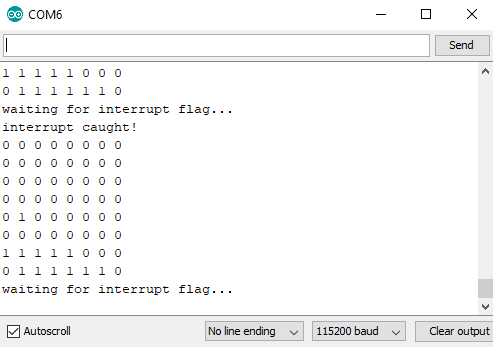
Where UPPER_LIMIT, LOWER_LIMIT, and HYSTERESIS are declared above. Opening the serial monitor will display a table of which interrupts have been fired, if any. Play around with the values of UPPER_LIMIT, LOWER_LIMIT, and HYSTERESIS and observe their effect on the firing of interrupts. The interrupt table should look similar to the below image, obviously with different interrupts firing depending on what the Grid-EYE is looking at.
Example 3 - Device Temperature
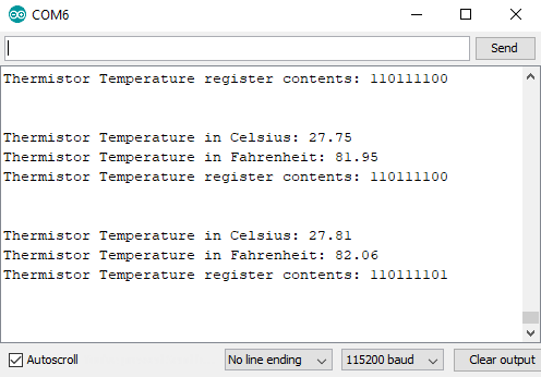
To pull up the next example, go to File > Examples > SparkFun GridEYE AMG88 Library > Example3-DeviceTemperature to open the example sketch. This example is relatively simple, and merely checks the devices temperature. To get device temperature, there are 3 functions we can use, getDeviceTemperature(), which returns our temperature in Celsius, getDeviceTemperatureFahrenheit(), which returns our temperature in Fahrenheit getDeviceTemperatureRaw() returns the raw binary content of the thermistor register. Opening the serial monitor should yield an image similar to the one below.
Example 4 - Processing Heat Cam
Note: Processing is a software that enables visual representation of data, among other things. If you've never dealt with Processing before, we recommend you also check out the Arduino to Processing tutorial. Follow the below button to go ahead and download and install Processing.
This next example involves the Processing IDE. Processing listens for serial data, so we'll need to get our Arduino producing serial data that makes sense to Processing. To pull up the next example, go to File > Examples > SparkFun GridEYE AMG88 Library > Example4-ProcessingHeatCam to open the example sketch. This sketch simply prints a comma separated list of our temperatures over serial for Processing to listen to.
Once this sketch is uploaded, we need to tell Processing how to turn this data into a visualization. The Processing sketch to do this is located in the same folder as Example 4. So go to Documents > Arduino > SparkFun_GridEYE_AMG88_Library > examples > Example4-ProcessingHeatCam > HeatCam and open the HeatCam file in Processing. Attempting to run the sketch will show us available serial ports in the debug window.
Identify which serial port your Arduino is on, for instance, my RedBoard is on COM6, which corresponds to [1] in the above image, so I will need to change 0 to 1 in the following line to ensure Processing is listening in the right location.
language:c
myPort = new Serial(this, Serial.list()[0], 115200);
Once I've done this, we should be able to run the Processing sketch and it will give us a nice visualization of the pixels on our Grid-EYE. Move your face or hand in front of the sensor and see what it looks like on the screen. The output should look similar to the below image, which is output from the Grid-EYE being pointed at a glass of ice water and a lava lamp.
Example 5 - Hot Pixel
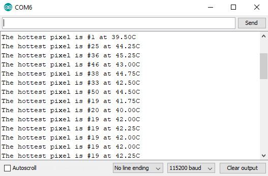
To pull up the next example, go to File > Examples > SparkFun GridEYE AMG88 Library > Example5-HotPixel to open the example sketch. This example runs through each pixel and finds the hottest one, then outputs the location and temperature of that pixel. It does this by comparing the current hotPixelValue temperature to the temperature of the current pixel. If the current pixel is hotter, its value is stored in hotPixelValue. The output of this sketch should look something like the below image.
Resources and Going Further
Thanks for reading! Now that you've successfully got your Grid-EYE up and running, it's time to incorporate it into your own project! We're excited to see what you build with the Grid-EYE. If you're left needing more Grid-EYE-related documentation, check out some of these resources:
- Schematic (PDF) -- PDF schematic of the Grid-EYE Breakout board.
- Eagle Files (ZIP) -- PCB design files for the Grid-EYE Breakout.
- Datasheet (PDF) -- Loads of information about the Grid-EYE's electrical characteristics, registers, communication specifications, and more.
- Qwiic Landing Page
- GitHub Repos
- Product Repo -- Design files and example code all related to the Grid-EYE.
- Library Repo -- Arduino Library
- SFE Product Showcase
Need some inspiration for your next project? Check out some of these related tutorials:
FLIR Lepton Hookup Guide
MLX90614 IR Thermometer Hookup Guide
Or maybe mirror heat signatures with addressable WS2812 LEDs:
Or check out this blog post for more ideas!
