MLX90614 IR Thermometer Hookup Guide
 jimblom
 Introduction
Is your IC too hot to touch? (Too scared to even chance it?) Need to monitor for temperature transients so you can flip a fan on or off? Just want to create your own, hackable non-contact thermometer? Sounds like a job for the Melexis MX90614 Infrared Thermometer!
Or if you want an IR thermometer integrated into an Arduino-compatible evaluation board, check out the SparkFun IR Thermometer Evaluation Board.
The IR Thermometer Evaluation Board is equipped with an MLX90614-ABB -- a simple-to-use, but very powerful single-zone infrared thermometer, capable of sensing object temperatures between -70 and 380°C. Using SMBus -- an I2C-like interface -- to communicate with the chip means you only need to devote two wires from your microcontroller to interface with it.
Covered In This Tutorial
This tutorial aims to quickly familiarize you with the MLX90614 IR thermometer and demonstrate how to interface it with an Arduino. It covers hookup of both the bare sensor (to an Arduino) and the SparkFun MLX90614 Evaluation Board. It dips into theory, paraphrases some datasheet tables, demonstrates example circuits, and introduces a new Arduino library.
The tutorial is split into the following sections:
- MLX90614 Overview -- A brief introduction to IR thermometer theory and the MLX90614's specifications and interfaces.
- Evaluation Board Overview -- A quick rundown of the evaluation board's features.
- Hardware Hookup -- How to create a circuit around the bare sensor and/or interface with the evaluation board.
- MLX90614 Arduino Library -- Installing and using the SparkFunMLX90614 infrared thermometer library.
Suggested Reading
This tutorial builds on a few lower-level concepts. If you're unfamiliar with these topics, consider checking out those tutorials first:
What is an Arduino?
Pulse Width Modulation
Integrated Circuits
I2C
MLX90614 Overview
Internally, the MLX90614 is a pairing of two devices: an infrared thermopile detector and a signal-conditioning application processor.
Per the Stefan-Boltzman law, any object that isn't below absolute zero (0°K) emits (non-human-eye-visible) light in the infrared spectrum that is directly proportional to its temperature. The special infrared thermopile inside the MLX90614 senses how much infrared energy is being emitted by materials in its field of view, and produces an electrical signal proportional to that.
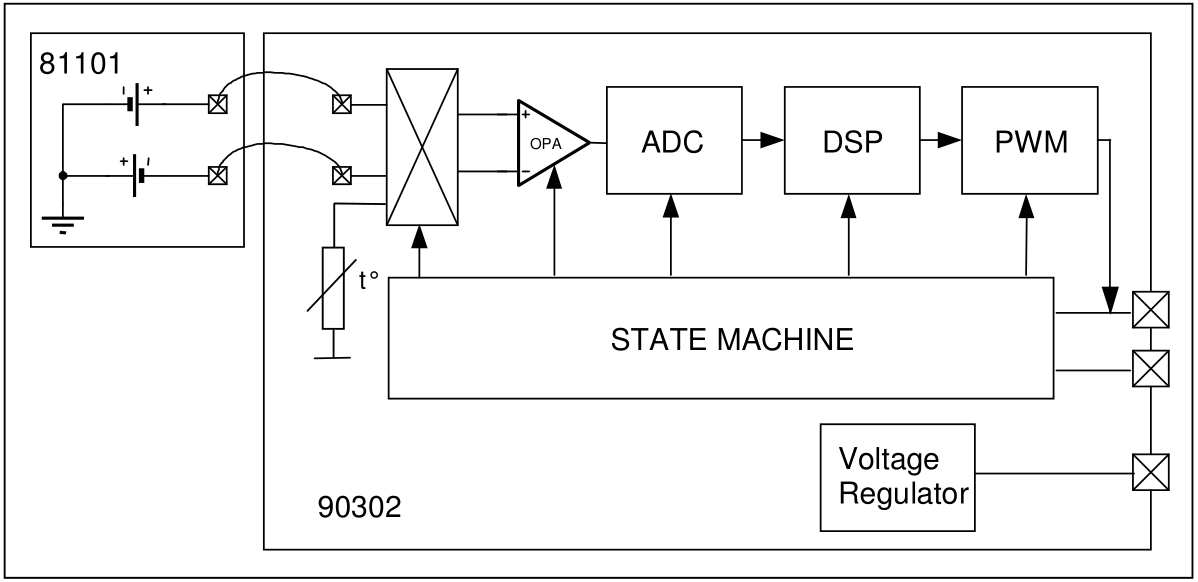
That voltage produced by the thermopile is picked up by the application processor's 17-bit ADC, then conditioned before being passed over to a microcontroller.
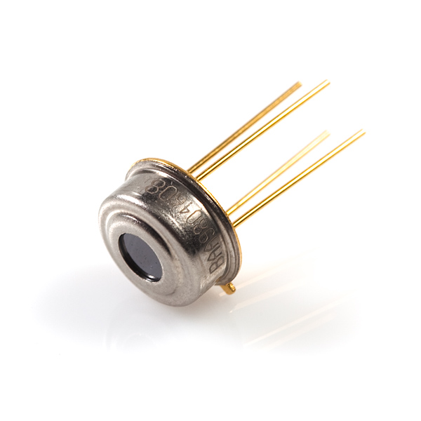
MLX90614 Pinout
The MLX90614 comes in a TO-39 "can" package with four legs: two for power, and two for the SMBus interface. A "notch" on the package helps to indicate which pin is which.

Capabilities
The MLX90614 produces two temperature measurements: an object and an ambient reading. The object temperature is the non-contact measurement you'd expect from the sensor, while the ambient temperature measures the temperature on the die of the sensor. The ambient can be useful to calibrate the data, but the real meat of our readings will come from the object temperature measurement.
The object temperature measurements can range from -70 to 382.2 °C (-94 to 719.96 °F), while the ambient temperature reading ranges from -40 to 125 °C.
Both the ambient temperature and object temperatures have a resolution of 0.02 °C.
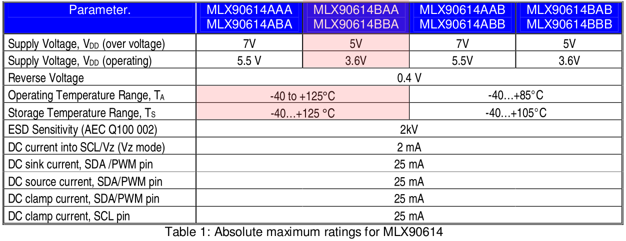
MLX90614BAA
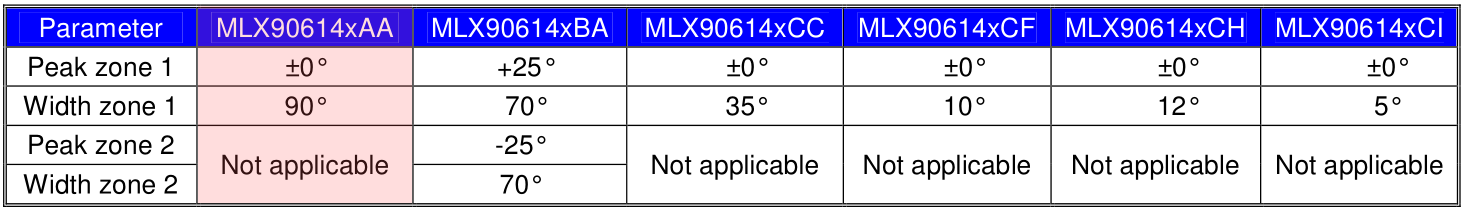
There are many varieties of the MLX90614 out there, each suffixed with three letters. The different sensor options vary by operating voltage, number of IR thermopiles, and whether they filter inside our outside the sensor. We're carrying the MLX90614BAA, which is rated for a 3V operating voltage with a single infrared sensor and an internal filter.
The variant also determines the field of view, which on the MLX90614BAA is 90°.
Speaking of which...
Field of View -- Distance vs. Spot Diameter
An IR thermometer's field-of-view (FOV) is a critical property to be aware of. It determines the relationship between the distance from an object and the area of space being observed. The MLX90614's field of view is cone-shaped -- its sensing area is very narrow if it's near the object, but gets increasingly wider as it moves farther away.
The MLX90614BAA has a relatively wide field-of-view angle: 90°. That means for every 1cm you move away from an object, the sensing area grows by 2cm. If you're one foot away from an object (30.48cm), the sensing area will be two feet (60.96cm).
Output Interfaces
The MLX90614 supports two interfaces -- though you'll need one to access the other. The two-wire SMBus interface is the primary means for communicating with the IR sensor. Once you've set up an SMBus interface, you can later configure the MLX90614 to produce a pulse-width modulated (PWM) signal representing the measured temperature(s).
SMBus (I2C)
The sensor is configured and read from over a 2-wire SMBus interface -- very similar, and nearly functionally equivalent to I2C. The two signals -- SDA and SCL -- carry the data and clock signals respectively. A master device controls the clock, while the data signal is bi-directionally controlled.
Every MLX90614 has a default I2C address of 0x5A, but that address can be re-written -- one of the major features supported by the device. By reconfiguring the address of an MLX90614, you can add multiple devices (up to 127!) to the same bus to get a larger temperature map.
One last bit to note about the SMBus interface -- every read or write transmission should be completed with an 8-bit CRC (CRC-8-CCITT) check using a x8+x2+x1+x0 polynomial -- handy for that extra bit of data-confidence.
PWM & "Thermal Relay"
The MLX90614's data can also be read via a PWM interface. In this use case just one wire is required to read from the sensor: SDA. To use the PWM interface, the MLX90614 has to be configured over the SMBus to produce it.
The PWM output can be difficult to use with a microcontroller, but it is very powerful if you want to use the MLX90614 to directly control a relay or other externally triggered device.
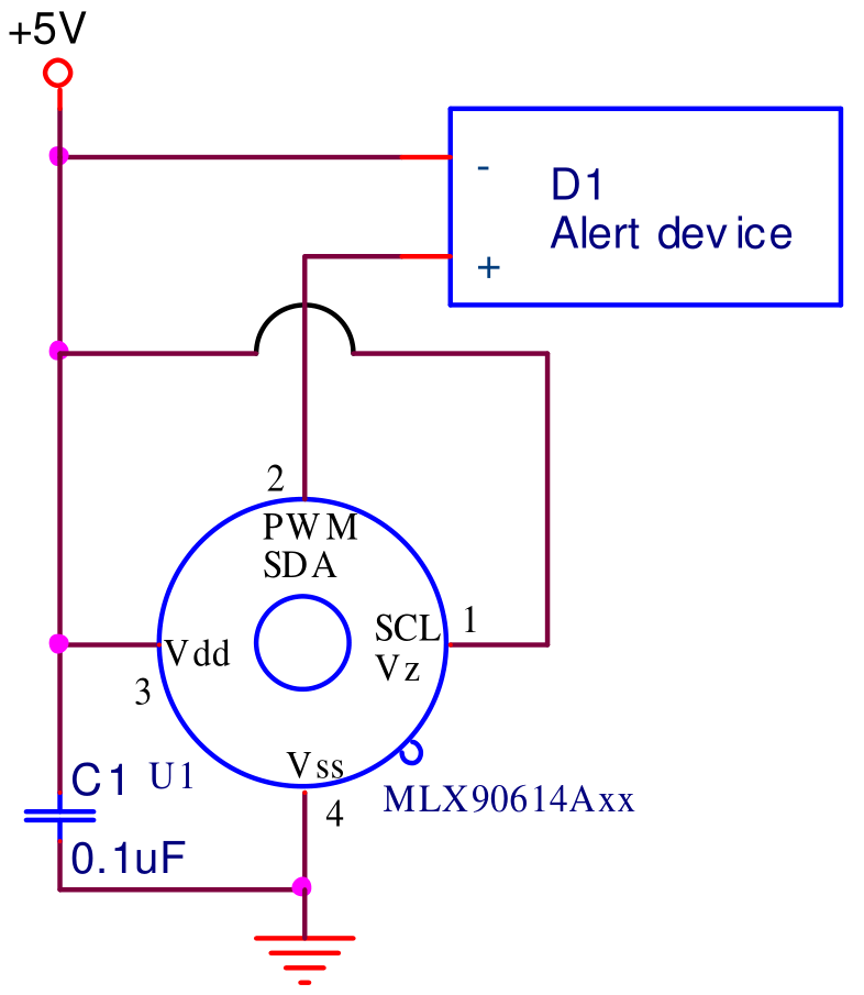
By configuring the sensor's range -- setting minimum and/or maximum temperature values -- the PWM output can be turned into a "thermal relay" signal. The PWM signal will be low unless the the object temperature exceeds the set threshold.
For a more exhaustive overview of the MLX90614, check out the datasheet.
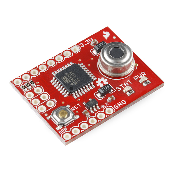
Evaluation Board Overview
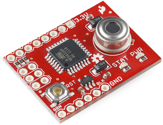
The SparkFun IR Thermometer Evaluation Board wires the MLX90614 up to an ATmega328 microprocessor so you can quickly begin developing with the sensor instead of fussing with wires and breadboards.
The ATmega328 on the Evaluation Board comes pre-programmed with UART-based example code, and an Arduino bootloader. After monitoring the temperature over the serial interface, you can use that same serial port to upload code of your own!
The Pinout
A pair of headers on opposite sides of the evaluation board break out a handful of microprocessor signals and power busses, and the ATmega's SPI interface is available on the ICSP header:
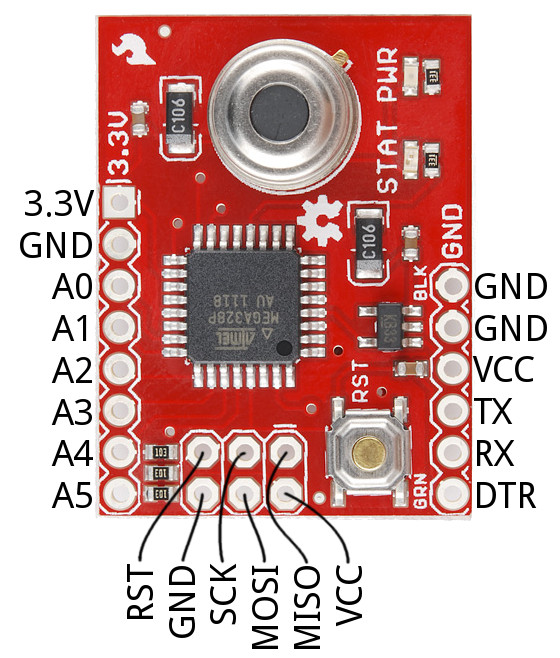
The pins are all labeled on the bottom side of the board, in case you don't want to refer back to this picture.
| Pin Label | Equivalent Arduino Pin | Notes |
|---|---|---|
| Serial Programming/Interface Header | ||
| GND | Ground (0v) | |
| GND | Ground (0v) | |
| VCC | Voltage supply input | |
| TX | 1 | UART input |
| RX | 0 | UART output |
| DTR | Auto-reset control from FTDI programmer | |
| GPIO/Power Header | ||
| 3.3V | 3.3V | 3.3V supply (regulated from the VCC input) |
| GND | GND | Ground (0v) |
| PC0 | A0 | Analog input and/or digital in/out |
| PC1 | A1 | Analog input and/or digital in/out |
| PC2 | A2 | Analog input and/or digital in/out |
| PC3 | A3 | Analog input and/or digital in/out |
| SDA | A4 | Serial data line to MLX90614 – more devices can be added to I2C bus. |
| SCL | A5 | Serial clock to MLX90614 – more devices can be added to I2C bus. |
| ICSP Header | ||
| RST | Reset | Arduino active-low reset |
| GND | GND | Ground (0v) |
| SCK | 13 | SPI clock and/or digital in/out |
| MOSI | 11 | SPI master-out/slave-in and/or digital in/out |
| MISO | 12 | SPI master-in/slave-out and/or digital in/out |
| VCC | 3.3V | 3.3V supply (regulated from the VCC input) |
The extra GPIO allow you to build the "Evaluation Board" into a project centerpiece. With seven unused GPIO you can hookup Serial 7-Segment Displays, LCDs, or many other components. Plus, the I2C can be expanded with additional senors -- whether it's a light sensor or a motion sensor.
LED Indicators
The evaluation board has a green LED wired up to digital pin 8 (PB0). The LED is active-low, so writing the pin LOW will turn the LED on, and HIGH will turn it off.
The nearby red power LED should illuminate whenever the board is powered.
Hardware Hookup
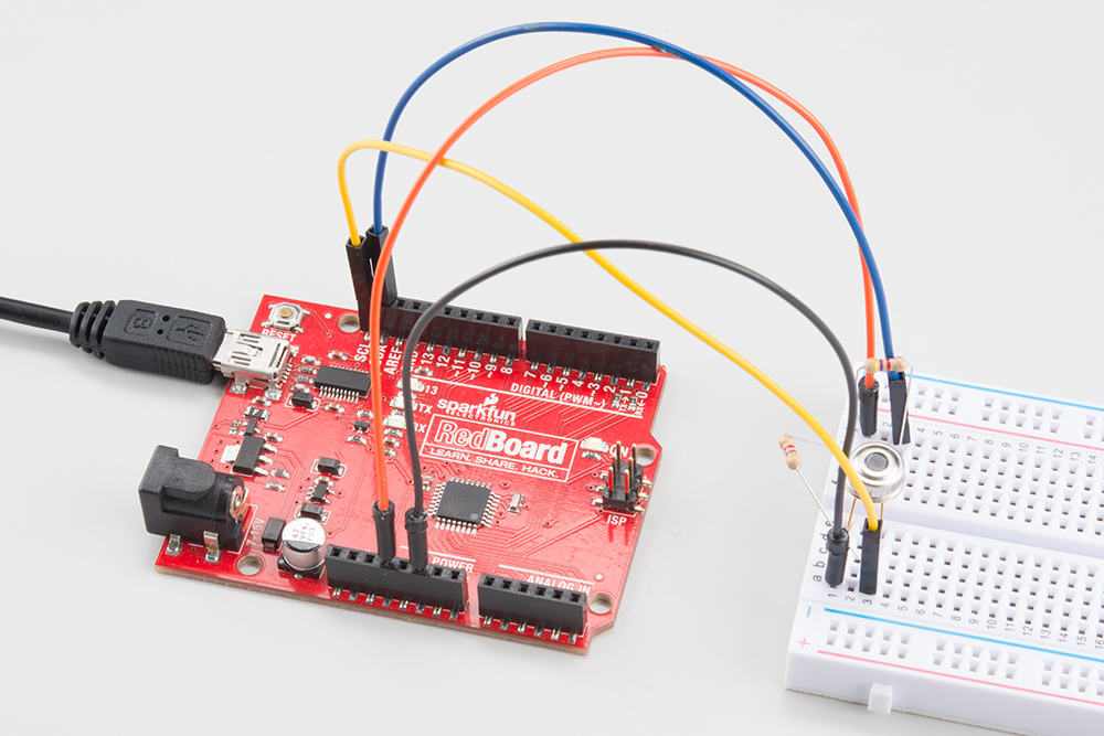
Hooking up the MLX90614
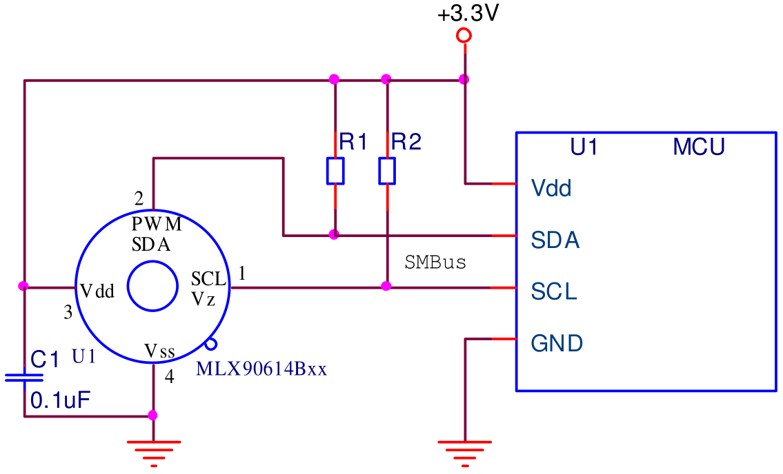
If you're not using the SparkFun Evaluation Board, you can wire the MLX90614 up to just about any Arduino-compatible microcontroller (or, really, any µC with an I2C interface). Power the sensor using the 3.3V rail, wire up SDA-to-SDA and SCL-to-SCL, and add 4.7kΩ pull-up resistors to the two I2C signals.
| MLX90614 Pin | Arduino Pin | Note |
|---|---|---|
| VDD | 3.3V | Nearby 0.1µF decoupling capacitor |
| VSS | 0V | Nearby 0.1µF decoupling capacitor |
| SDA/PWM | SDA (A4) | Pulled up to 3.3V via a 4.7kΩ Resistor |
| SCL | SCL (A5) | Pulled up to 3.3V via a 4.7kΩ Resistor |
Use the "notch" on the sensor to help identify which pin is which.
Hooking Up the IR Thermometer Evaluation Board
To use the evaluation board, you'll need to solder something to at least the 6-pin serial header. We like right-angle male headers for this purpose, but straight headers may also work.
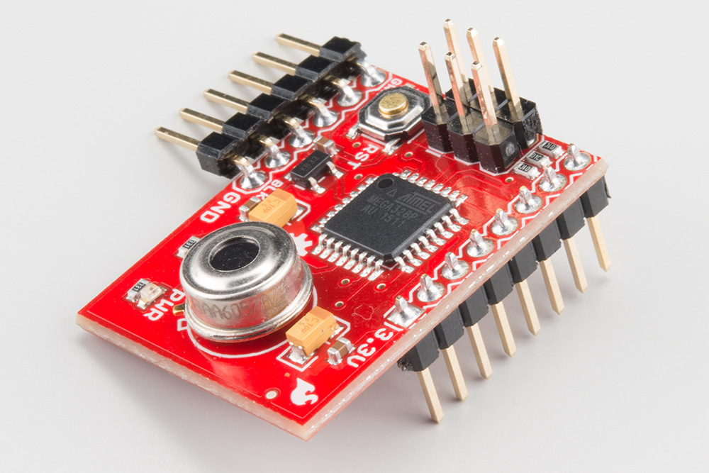
While you're at it, you may also want to solder headers to the GPIO header and/or the ICSP header -- just in case you want to interface with the SPI interface or analog inputs.
Connecting an FTDI Basic
The easiest way to interact with the MLX90614 Evaluation Board is via a 3.3V FTDI Basic Breakout or a 3.3V I/O FTDI Cable, which both provide power and set up a serial interface between the eval board and your computer.
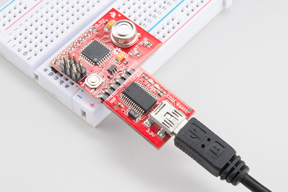
Take care to match up the "GRN" and "BLK" labels (or the green and black wires of the FTDI cable) between the two devices! Also note that the FTDI can supply, at most, about 50mA. That'll be enough for this board, but if you add more devices to the circuit, you may need to add a separate power source.
The FTDI also sets up a programming interface -- using the pre-programmed serial bootloader and the Arduino IDE.
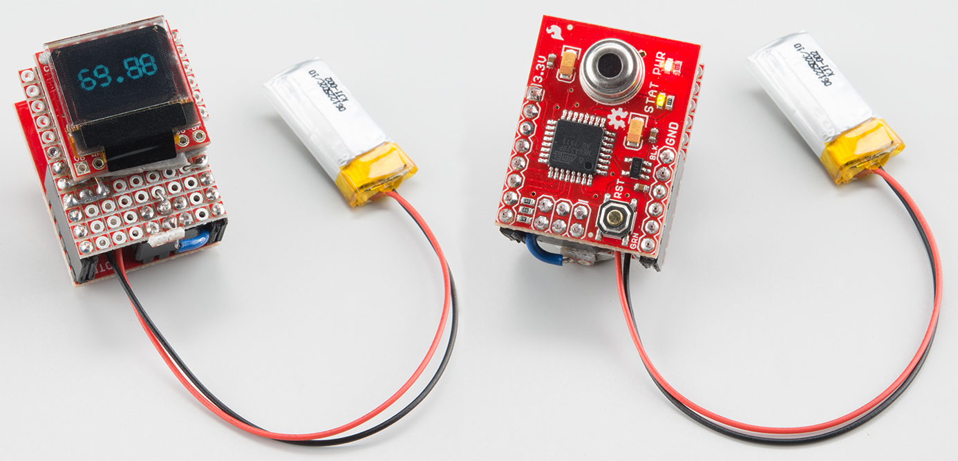
Using the Pre-Programmed Firmware
The IR Thermometer Breakout board ships with simple example code, allowing you to quickly test the functionality of the MLX90614. The demo code outputs the ambient and object temperatures over the serial interface at 38400 bps.
To view the output, open a serial terminal of your choice (if you don't already have one, check out our Serial Terminal Basics tutorial for suggestions). And set the baud rate to 38400 bps (8 data bits, no parity, 1 stop bit). You should see the object temperature readings stream by every second-or-so.
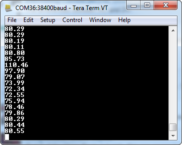
The "STAT" LED should also blink every time new data is produced.
Once you've gotten a handle on that, check out the next section to start writing your own IR thermometer-interfacing code!
MLX90614 Arduino Library
Using an Arduino to interact with the sensor is almost as easy as hooking it up, thanks to our IR Thermometer Arduino library.
Download and Install the Arduino Library
Download the library from our GitHub repository, or click the button below to download a ZIP file.
To add the library to your Arduino sketchbook, open the IDE, navigate to Sketch > Include Library > Add .ZIP Library... and select the ZIP folder you just downloaded.
If you're using an older version of the IDE, or need help installing the library, check out our How To Install an Arduino Library tutorial.
Setting Up the Evaluation Board in Arduino
If you're using the SparkFun IR Thermometer Evaluation Board, set the Arduino board to Arduino Pro or Pro Mini, ATmega328 (3.3V, 8MHz).
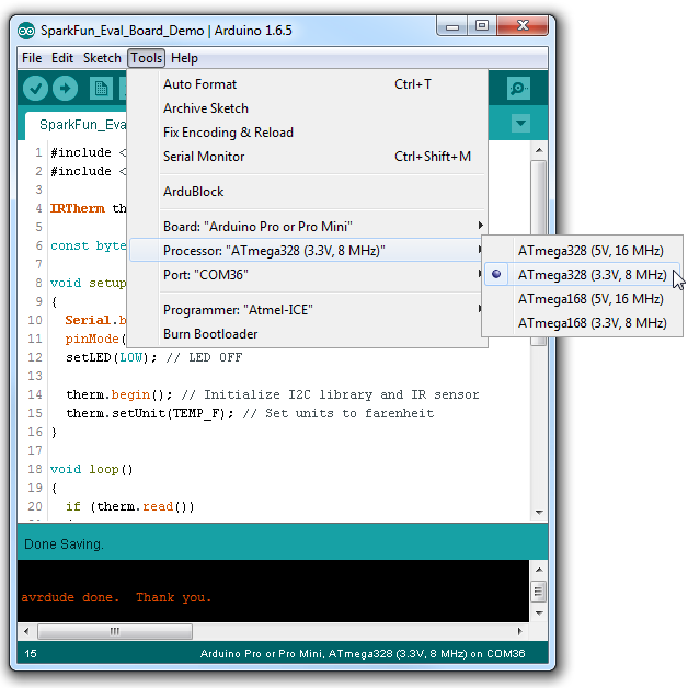
First, navigate to the Tools > Board and select Arduino Pro or Pro Mini. Then go to Tools > Processor and select ATmega328 (3.3V, 8MHz).
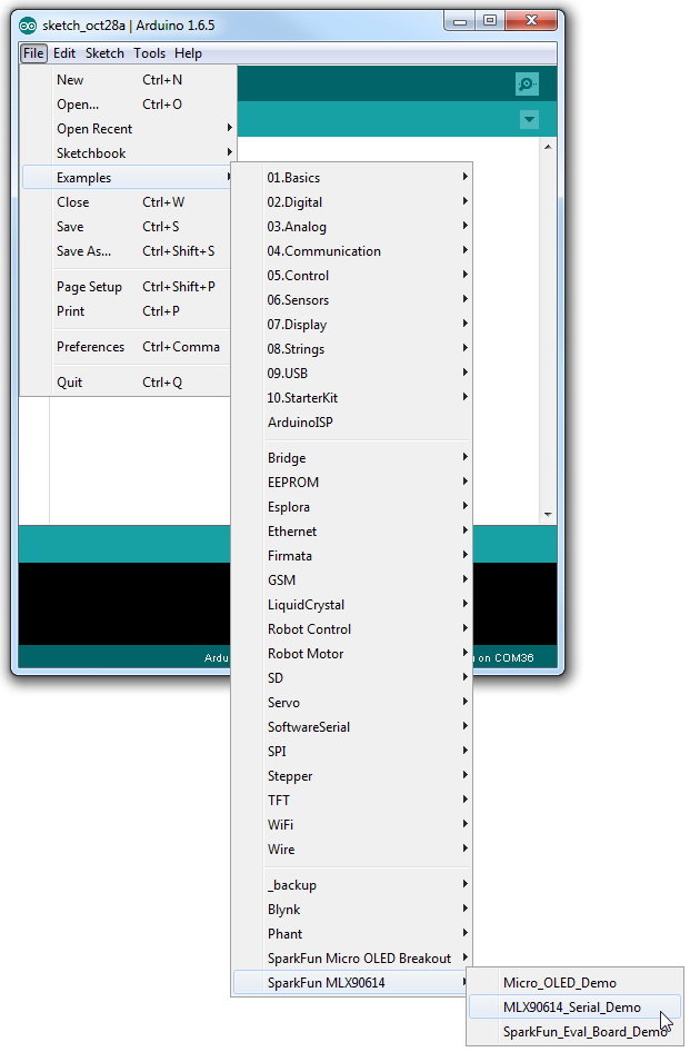
Run the MLX90614_Serial_Demo Example
The SparkFun MLX90614 Arduino includes a handful examples, which demonstrate everything from reading the sensor's values to adjusting emissivity, to modifying the 7-bit address.
Open the most basic example by navigating to File > Examples > SparkFun MLX90614 > MLX90614_Serial_Demo.
Upload the sketch, then open your serial monitor, setting the baud rate to 9600 bps. You should see both the ambient temperature and the object temperature begin to stream by.
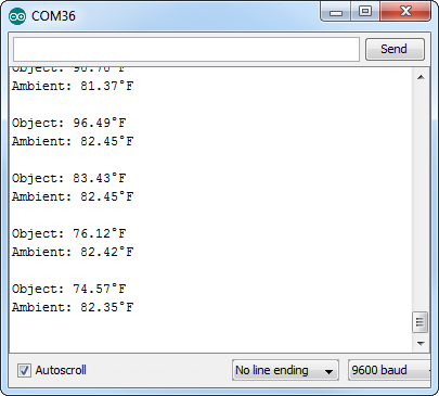
Try aiming the sensor at objects you have lying around. How hot is that soldering iron? Or shine it in your ear to make sure you don't have a fever!

Using the MLX90614 Library
There are a few lines of code you'll probably stick in every MLX90614-interfacing code you'll write. To begin, include the SparkFunMLX90614 library and Wire. In that same global area, you may want to define an IRTherm object to be used throughout the rest of the sketch.
language:c
#include <Wire.h> // Include Wire.h - Arduino I2C library
#include <SparkFunMLX90614.h> // Include IR thermometer library

IRTherm temp; // Create an IRTherm object called temp
Then, usually in the setup() function, initialize the sensor by calling begin(). This function optionally takes a parameter -- the 7-bit address of your sensor -- but if left empty it assumes the address is set to the default (0x5A). Unless you want to use the default units of Celsius, also consider calling the setUnit() function to change the units to either Kelvin or Farenheit.
language:c
temp.begin(); // Initialize I2C library and the MLX90614
temp.setUnit(TEMP_F); // Set units to Farenheit (alternatively TEMP_C or TEMP_K)
Getting values out of the sensor is a two-step process: read from the sensor then get the updated values. To read from the sensor, call the read() function, which will return 1 on success (or 0 if it fails). If the read() function succeeds, you can grab the updated ambient and object temperatures using the ambient() and object() functions:
language:c
if (temp.read()) // Read from the sensor
{ // If the read is successful:
  float ambientT = temp.ambient(); // Get updated ambient temperature
  float objectT = temp.object(); // Get updated object temperature
  Serial.println("Ambient: " + String(ambientT));
  Serial.println("Object: " + String(objectT));
  Serial.println();
}
These values will already be converted to the units you set using the setUnit() function.
To find out more about the SparkFunMLX90614 library, check out some of the other examples in the library! Or read through the (exhaustive) comments in the header file
Resources and Going Further
Here are a few resources you may find handy as you continue building your IR thermometer-based project:
- SparkFun IR Thermometer Evaluation Board - MLX90614 GitHub Repo -- The PCB design files and the firmware we program onto our IR Thermometer Evaluation Boards (beware pre-Arduino code lives here!).
- SparkFun MLX90614 Arduino Library GitHub Repo -- The GitHub home for our MLX90614 Arduino library.
- MLX90614 Datasheet
- Melexis' MLX90614 Product Page -- Good source for documentation and other product information.
- Infrared Temperature Measurement Theory and Application -- Excellent overview of the theory behind IR thermometers.
If you want to continue your SparkFun tutorial-reading journey, here are a few related tutorials you may enjoy:
Or check out this blog post for ideas: