Qwiic dToF Imager (TMF882X) Hookup Guide
 bboyho,
  Elias The Sparkiest
Arduino Examples
Below are a few examples that are highlighted from the Arduino library.
Example 1: Basic
The following example uses the RedBoard Artemis. However, you could also use any Arduino-compatible microcontroller listed earlier in this tutorial if it has enough memory.

After installing the library, open the sketch in Arduino: File > Examples > SparkFun Qwiic TMF882X Arduino Library > Example-01_Basic. The following code was copied from the Arduino Library for your convenience. If you have not already, select your Board (in this case the RedBoard Artemis), and associated COM port. Upload the code to the board.
language:c
/*

  Example-01_Basic.ino

  This demo shows a basic use of a TMF882X device. The device is connected to,
  and a single reading is taken for each loop iteration.

  Supported Boards:

   SparkFun Qwiic dToF Imager - TMF8820        https://www.sparkfun.com/products/19036
   SparkFun Qwiic Mini dToF Imager - TMF8820   https://www.sparkfun.com/products/19218
   SparkFun Qwiic Mini dToF Imager - TMF8821   https://www.sparkfun.com/products/19451
   SparkFun Qwiic dToF Imager - TMF8821        https://www.sparkfun.com/products/19037

  Written by Kirk Benell @ SparkFun Electronics, April 2022

  Repository:
     https://github.com/sparkfun/SparkFun_Qwiic_TMF882X_Arduino_Library

  Documentation:
     https://sparkfun.github.io/SparkFun_Qwiic_TMF882X_Arduino_Library/

  SparkFun code, firmware, and software is released under the MIT License(http://opensource.org/licenses/MIT).
*/

#include "SparkFun_TMF882X_Library.h" //http://librarymanager/All#SparkFun_Qwiic_TMPF882X

SparkFun_TMF882X  myTMF882X;

// Structure to hold the measurement results - this is defined by the TMF882X SDK.

static struct tmf882x_msg_meas_results myResults;

void setup()
{

    delay(1000);
    Serial.begin(115200);
    Serial.println("");

    Serial.println("In setup");
    Serial.println("==============================");

    // Initialize the TMF882X device
    if(!myTMF882X.begin())
    {
        Serial.println("Error - The TMF882X failed to initialize - is the board connected?");
        while(1);
    }else
        Serial.println("TMF882X started.");

    // The device is now ready for operations
}

void loop()
{
    delay(2000);

    // get a Measurement
    if(myTMF882X.startMeasuring(myResults))
    {
        // print out results
        Serial.println("Measurement:");
        Serial.print("     Result Number: "); Serial.print(myResults.result_num);
        Serial.print("  Number of Results: "); Serial.println(myResults.num_results);

        for (int i = 0; i < myResults.num_results; ++i)
        {
            Serial.print("       conf: "); Serial.print(myResults.results[i].confidence);
            Serial.print(" distance mm: "); Serial.print(myResults.results[i].distance_mm);
            Serial.print(" channel: "); Serial.print(myResults.results[i].channel);
            Serial.print(" sub_capture: "); Serial.println(myResults.results[i].sub_capture);

        }
        Serial.print("     photon: "); Serial.print(myResults.photon_count);
        Serial.print(" ref photon: "); Serial.print(myResults.ref_photon_count);
        Serial.print(" ALS: "); Serial.println(myResults.ambient_light); Serial.println();

    }

}
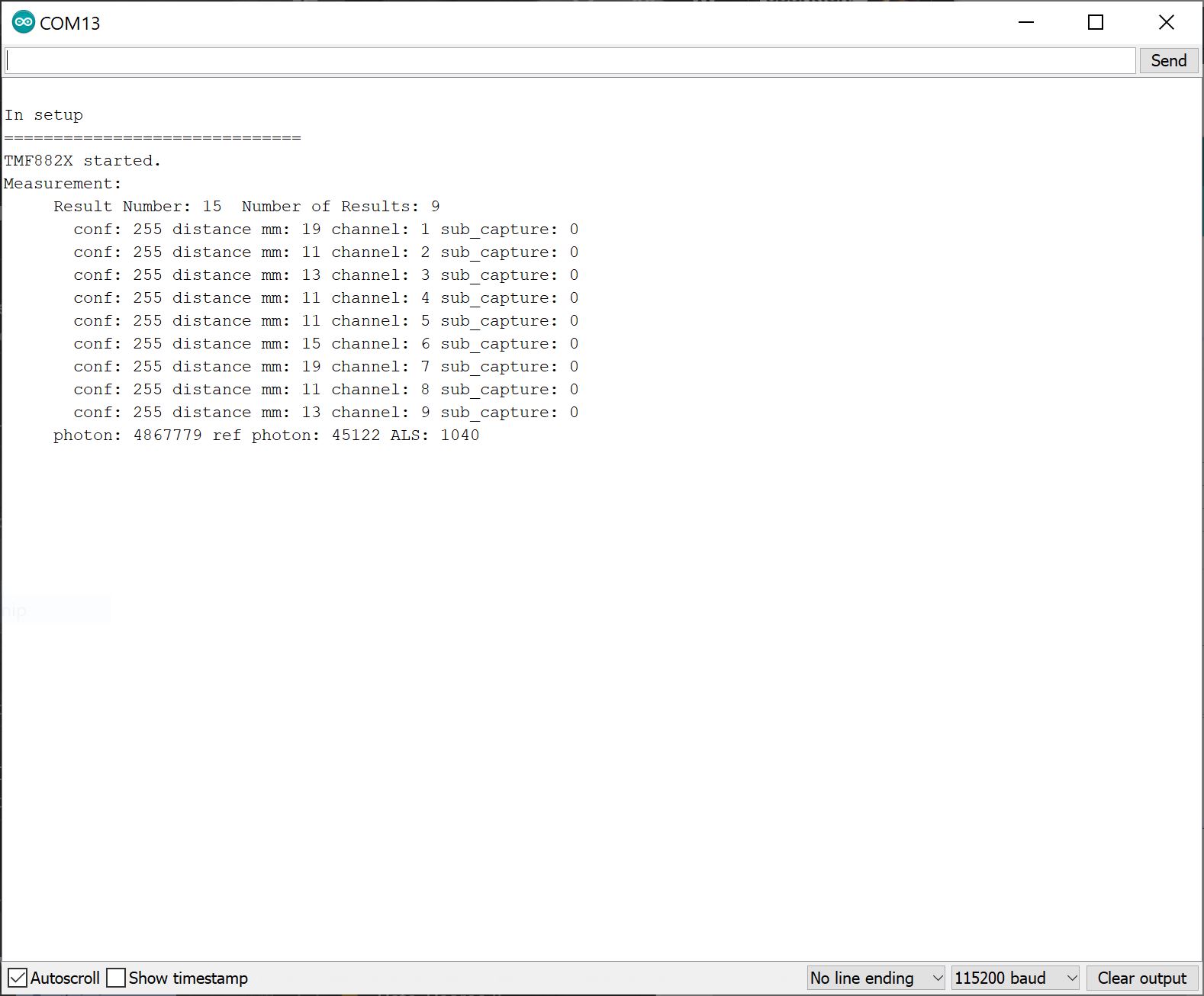
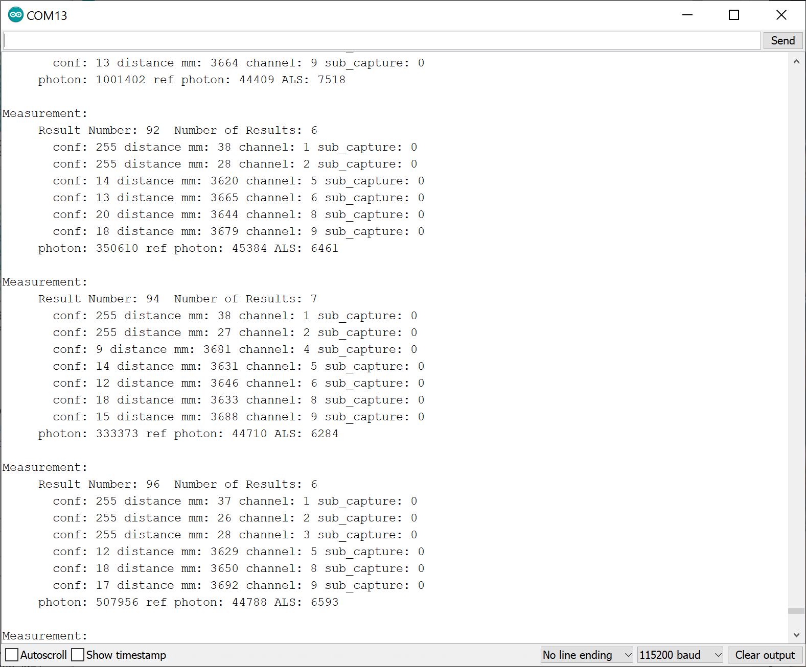
Open the Arduino Serial Monitor set to 115200 baud. Place an object like your finger or a flat, rigid object in front of the dToF Imager's IC. You should see something similar in the output below. The readings show a high confidence value [.confidence values are between 0 and 255, with 255 being the highest] and the distance measurements in millimeters [.distance_mm] for each channel [.channel]. The output also provides information about the total photons received [.photon_count], reference photon [.ref_photon_count], and tutorial ambient light [.ambient_light]received by the channels.
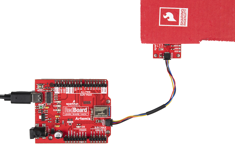
Try positioning the object so that channel 1 through 3 is covered and close to the TMF8820/TMF8821. In this case, we used a piece of cardboard to partially cover the sensor. Make sure to orient the board with respect to the SPADs as shown in the image below to easily view the changes in the output.
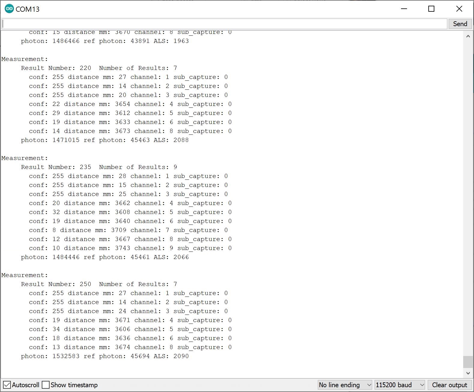
With the Serial Monitor still open, you should see something similar to the output below. You will notice that the sensor was able to detect an object over channels 1 through 3 with a high confidence. The values for the other channels that were not covered by the cardboard showed a low confidence and longer distance values, which were close to the distance between the top of my desk and the ceiling (i.e. 12 feet). The TMF8820/TMF8821 may not display a result if the SPAD does not receive a reflected pulse.
Example 5: Verbose
With the library installed, open the sketch in Arduino: File > Examples > SparkFun Qwiic TMF882X Arduino Library > Example-05_Verbose. The following code was copied from the Arduino Library for your convenience. If you have not already, select your Board (in this case the RedBoard Artemis), and associated COM port. Upload the code to the board.
language:c
/*

  Example-05_Verbose.ino

  The TMF882X Arduino library uses the TMF882X Software Development Kit (SDK) from
  AMS to interface with the sensor.

  The AMS SDK is able to print out informational messages during normal operation, as
  well as debug messages. This example shows how to enable those messages and direct
  them to a Serial device for output.

  Supported Boards:

   SparkFun Qwiic dToF Imager - TMF8820        https://www.sparkfun.com/products/19036
   SparkFun Qwiic Mini dToF Imager - TMF8820   https://www.sparkfun.com/products/19218
   SparkFun Qwiic Mini dToF Imager - TMF8821   https://www.sparkfun.com/products/19451
   SparkFun Qwiic dToF Imager - TMF8821        https://www.sparkfun.com/products/19037

  Written by Kirk Benell @ SparkFun Electronics, April 2022

  Repository:
     https://github.com/sparkfun/SparkFun_Qwiic_TMF882X_Arduino_Library

  Documentation:
     https://sparkfun.github.io/SparkFun_Qwiic_TMF882X_Arduino_Library/

  SparkFun code, firmware, and software is released under the MIT License(http://opensource.org/licenses/MIT).
*/

#include "SparkFun_TMF882X_Library.h"    //http://librarymanager/All#SparkFun_Qwiic_TMPF882X

SparkFun_TMF882X  myTMF882X;

static struct tmf882x_msg_meas_results myResults;

void setup()
{

    delay(1000);
    Serial.begin(115200);
    Serial.println("");

    Serial.println("In setup");
    Serial.println("==============================");

    // The underlying TMF882X SDK can output a wide variety of information during
    // normal operation. It's very verbose.
    //
    // Enable this output as part of this demo.
    //
    // Pass in our output device - Serial

    myTMF882X.setOutputDevice(Serial);

    // Enable Info messages
    myTMF882X.setInfoMessages(true);

    // Enable Debug mode. Set this before calling begin to get initialization debug
    // information.

    myTMF882X.setDebug(true);

    if(!myTMF882X.begin())
    {
        Serial.println("Error - The TMF882X failed to initialize - is the board connected?");
        while(1);
    }else
        Serial.println("TMF882X started.");


}

void loop()
{
    delay(2000);

    // get a myResultsurment
    if(myTMF882X.startMeasuring(myResults))
    {
        // print out results
        Serial.println("Measurement:");
        Serial.print("     Result Number: "); Serial.print(myResults.result_num);
        Serial.print("  Number of Results: "); Serial.println(myResults.num_results);

        for (uint32_t i = 0; i < myResults.num_results; ++i)
        {
            Serial.print("       conf: "); Serial.print(myResults.results[i].confidence);
            Serial.print(" distance mm: "); Serial.print(myResults.results[i].distance_mm);
            Serial.print(" channel: "); Serial.print(myResults.results[i].channel);
            Serial.print(" sub_capture: "); Serial.println(myResults.results[i].sub_capture);

        }
        Serial.print("     photon: "); Serial.print(myResults.photon_count);
        Serial.print(" ref photon: "); Serial.print(myResults.ref_photon_count);
        Serial.print(" ALS: "); Serial.println(myResults.ambient_light); Serial.println();

    }

}
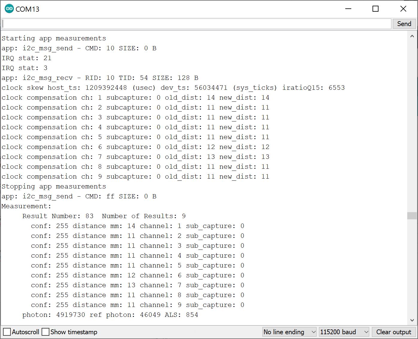
Open the Arduino Serial Monitor set to 115200 baud. The output is similar to the Basic example. However, there is additional information displayed. This information is useful for those debugging with the TMF8820 or TMF8821. The measurements were taken when an object was covering the IC completely.
Example 8: Factory Calibration
This example is suggested when placing the TMF8820 and TMF8821 its final application and when adjusting the SPAD mask selection. As suggested in the datasheet under 7.3 Calibration, "the calibration test shall be done in a housing with minimal ambient light and no target within 40 cm in field of view of the TMF8820/21."
With the library installed, open the sketch in Arduino: File > Examples > SparkFun Qwiic TMF882X Arduino Library > Example-08_FactoryCal. The following code was copied from the Arduino Library for your convenience. If you have not already, select your Board (in this case the RedBoard Artemis), and associated COM port. Upload the code to the board.
language:c
/*

  Example-08_FactoryCal.ino

  This example shows how to peform a Factory Calibration on the connected
  TMF882X device. Details on the calibration and it's use are contained in
  the TMF882X datasheet.

  Supported Boards:

   SparkFun Qwiic dToF Imager - TMF8820        https://www.sparkfun.com/products/19036
   SparkFun Qwiic Mini dToF Imager - TMF8820   https://www.sparkfun.com/products/19218
   SparkFun Qwiic Mini dToF Imager - TMF8821   https://www.sparkfun.com/products/19451
   SparkFun Qwiic dToF Imager - TMF8821        https://www.sparkfun.com/products/19037

  Written by Kirk Benell @ SparkFun Electronics, April 2022

  Repository:
     https://github.com/sparkfun/SparkFun_Qwiic_TMF882X_Arduino_Library

  Documentation:
     https://sparkfun.github.io/SparkFun_Qwiic_TMF882X_Arduino_Library/

  SparkFun code, firmware, and software is released under the MIT License(http://opensource.org/licenses/MIT).
*/


#include <SparkFun_TMF882X_Library.h>    //http://librarymanager/All#SparkFun_Qwiic_TMPF882X

SparkFun_TMF882X  myTMF882X;

void setup()
{

    delay(1000);
    Serial.begin(115200);
    Serial.println("");

    Serial.println("In setup");
    Serial.println("==============================");

    if(!myTMF882X.begin())
    {
        Serial.println("Error - The TMF882X failed to initialize - is the board connected?");
        while(1){}
    }else
        Serial.println("TMF882X started.");


    Serial.println();
    Serial.println("Performing a Factory Calibration.");
    Serial.println();
    // Perform a factory calibration of the connected device.

    // First set some config parameters to support the calibration
    struct tmf882x_mode_app_config tofConfig;
    if (!myTMF882X.getTMF882XConfig(tofConfig))
    {
        Serial.println("Error - unable to get device configuration.");
        while(1){}
    }

    // Change the APP configuration
    //  - set the reporting period to 500 milliseconds
    //  - set the iterations to 4,000,000 (4M) to perform factory calibration
    tofConfig.report_period_ms = 500;
    tofConfig.kilo_iterations = 4000;

    if (!myTMF882X.setTMF882XConfig(tofConfig))
    {
        Serial.println("Error - unable to set device configuration.");
        while(1){}
    }

    struct tmf882x_mode_app_calib factoryCal;

    // Peform the calibration
    if (!myTMF882X.factoryCalibration(factoryCal))
    {
        Serial.println("Error - Factory Calibration Failed.");
        while(1){}
    }

    // Output the calibration
    Serial.println("Calibration Complete");
    Serial.println();
    Serial.print("Calibration Data Length: ");
    Serial.println(factoryCal.calib_len);

    Serial.println("Calibration Data:");
    for (int i = 0; i < factoryCal.calib_len; i++)
    {
        Serial.print("   "); Serial.print(factoryCal.data[i]);

        if ( (i + 1) % 16 == 0 )
            Serial.println();
    }
    Serial.println();

}

void loop()
{
    delay(2000);

    // Nothing - just here for the calibration example
}
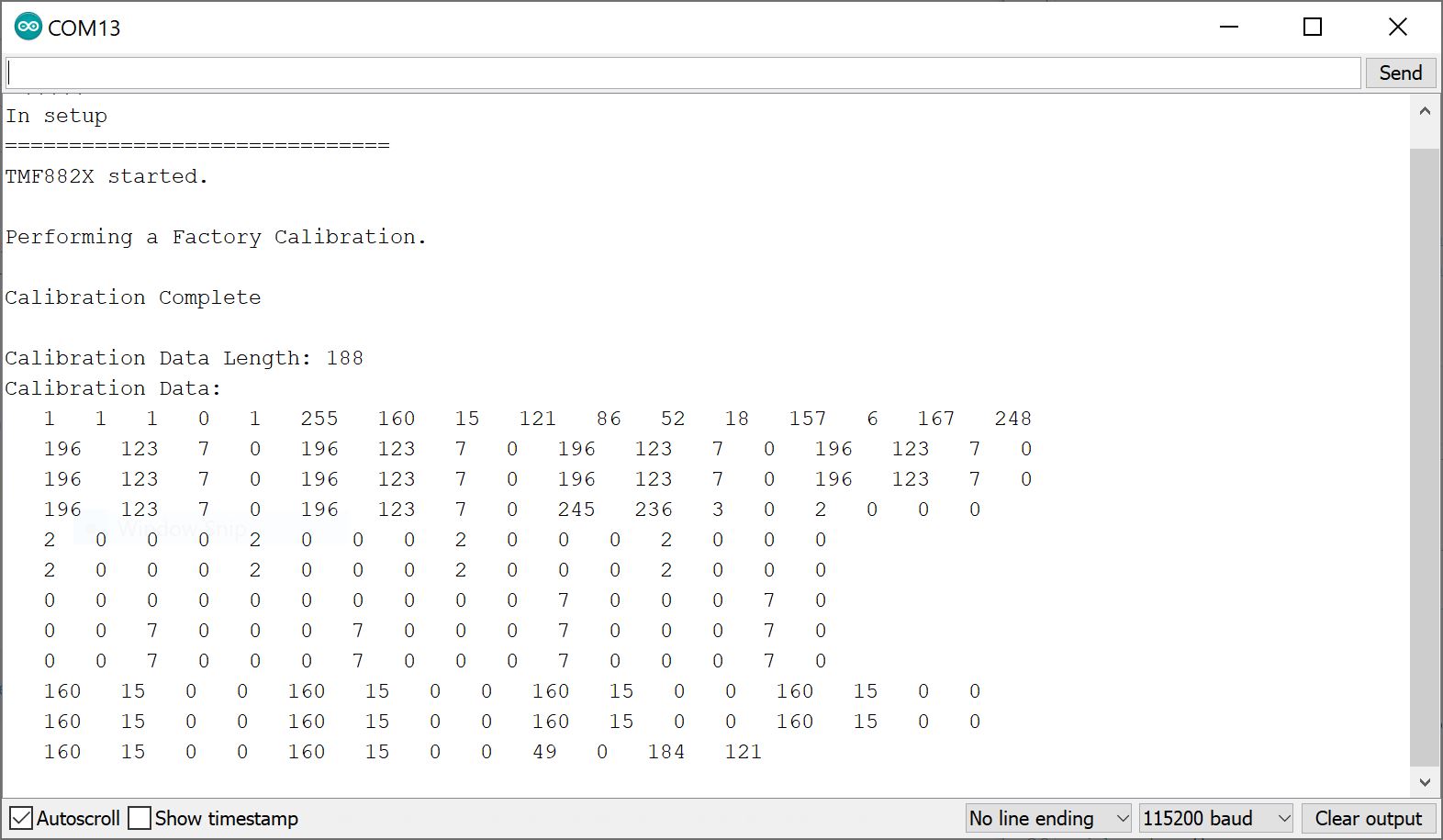
Open the Arduino Serial Monitor set to 115200 baud. You will see an output similar to the image below. You will need to follow the datasheet to calibrate the sensor properly.
Example 9: SPAD Map
SPAD_MAP_ID each time the TMF8820/TMF8821 is powered up. Make sure to also calibrate the sensor after adjusting the SPAD map.
With the library installed, open the sketch in Arduino: File > Examples > SparkFun Qwiic TMF882X Arduino Library > Example-09_SPADMap. The following code was copied from the Arduino Library for your convenience. If you have not already, select your Board (in this case the RedBoard Artemis), and associated COM port. Upload the code to the board.
language:c
/*

  Example-09_SPADMap.ino

  The Optical performance of the TMF882X is controled by a SPAD (Single Photon
  Avalanche Photodiode) Map.

  SPAD Maps are set using a SPAD Map ID, which are detailed in the TMF882X datasheet.

  This example shows how to determine the current SPAD Map on the device and change
  it to a desired map.

  Supported Boards:

   SparkFun Qwiic dToF Imager - TMF8820        https://www.sparkfun.com/products/19036
   SparkFun Qwiic Mini dToF Imager - TMF8820   https://www.sparkfun.com/products/19218
   SparkFun Qwiic Mini dToF Imager - TMF8821   https://www.sparkfun.com/products/19451
   SparkFun Qwiic dToF Imager - TMF8821        https://www.sparkfun.com/products/19037

  Written by Kirk Benell @ SparkFun Electronics, April 2022

  Repository:
     https://github.com/sparkfun/SparkFun_Qwiic_TMF882X_Arduino_Library

  Documentation:
     https://sparkfun.github.io/SparkFun_Qwiic_TMF882X_Arduino_Library/

  SparkFun code, firmware, and software is released under the MIT License(http://opensource.org/licenses/MIT).
*/

#include <SparkFun_TMF882X_Library.h>    //http://librarymanager/All#SparkFun_Qwiic_TMPF882X

static struct tmf882x_msg_meas_results myResults;


SparkFun_TMF882X  myTMF882X;

// What SPAD map to change to

#define NEW_SPAD_MAP 2

void setup()
{

    delay(1000);
    Serial.begin(115200);
    Serial.println("");

    Serial.println("In setup");
    Serial.println("==============================");

    if(!myTMF882X.begin())
    {
        Serial.println("Error - The TMF882X failed to initialize - is the board connected?");
        while(1){}
    }else
        Serial.println("TMF882X started.");


    // Let's change the SPAD map in use on this device.
    //
    // Get the current SPAD Map ID
    int spadMap =  myTMF882X.getCurrentSPADMap();
    Serial.println();
    Serial.print("Current SPAD Map ID: ");
    Serial.println(spadMap);

    // Now switch
    Serial.println("Switching SPAD Map to ID 2 - 3x3 Macro 1 off center");
    Serial.println();

    if (!myTMF882X.setCurrentSPADMap(NEW_SPAD_MAP))
    {
        Serial.println("Error -  Failed to set the SPAD Map - halting");
        while(1){}
    }

    // Let's make sure it worked
    spadMap =  myTMF882X.getCurrentSPADMap();

    if(spadMap != NEW_SPAD_MAP)
    {
        Serial.println("Error -  Failed to set the SPAD Map - halting");
        while(1){}
    }

    Serial.print("The new SPAD Map ID: ");
    Serial.println(spadMap);

    // Now set some config parameters to support the spad map
    struct tmf882x_mode_app_config tofConfig;

    if (!myTMF882X.getTMF882XConfig(tofConfig))
    {
        Serial.println("Error - unable to get device configuration.");
        while(1){}
    }

    // Change the APP configuration
    //  - set the reporting period to 500 milliseconds
    tofConfig.report_period_ms = 500;

    if (!myTMF882X.setTMF882XConfig(tofConfig))
    {
        Serial.println("Error - unable to set device configuration.");
        while(1){}
    }

}

void loop()
{
    delay(2000);

    // get a myResultsurment
    if(myTMF882X.startMeasuring(myResults))
    {
        // print out results
        Serial.println("Measurement:");
        Serial.print("     Result Number: "); Serial.print(myResults.result_num);
        Serial.print("  Number of Results: "); Serial.println(myResults.num_results);

        for (int i = 0; i < myResults.num_results; ++i)
        {
            Serial.print("       conf: "); Serial.print(myResults.results[i].confidence);
            Serial.print(" distance mm: "); Serial.print(myResults.results[i].distance_mm);
            Serial.print(" channel: "); Serial.print(myResults.results[i].channel);
            Serial.print(" sub_capture: "); Serial.println(myResults.results[i].sub_capture);

        }
        Serial.print("     photon: "); Serial.print(myResults.photon_count);
        Serial.print(" ref photon: "); Serial.print(myResults.ref_photon_count);
        Serial.print(" ALS: "); Serial.println(myResults.ambient_light); Serial.println();

    }
}
This example allows you to select the operating mode of the SPAD. The datasheet under "8.5.17 SPAD_MAP_ID Register" provides a list of acceptable values and modes. Note that certain values are reserved and zone configurations may not be available to use for the TMF8820 (i.e. limited to 3x3) or TMF8821 (i.e. limited to 3x3, 4x4, 3x6).
Once uploaded, open the Arduino Serial Monitor at 115200 baud and cover channels 1 through 3. The spad_map_id was changed to 2. The readings are similar to example 1 when the SPAD was using the default 3x3 Normal Mode. However, SPAD uses a different FOV and slightly offset.
If you have a TMF8821, try adjusting the SPAD to 4x4 normal mode with a 41°x52° FoV by changing spad_map_id to 7 (i.e. change the line #define NEW_SPAD_MAP 2 to #define NEW_SPAD_MAP 7). Then upload the code to the board.
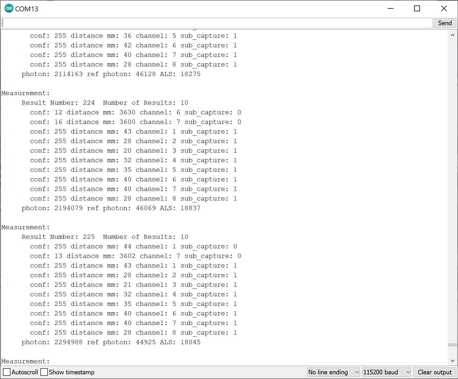
Open the Arduino Serial Monitor at 115200 baud and try to cover channels 9 through 16. You will see an output similar to the image below indicating that the respective channels were covered.
Example 11: Histogram
With the library installed, open the sketch in Arduino: File > Examples > SparkFun Qwiic TMF882X Arduino Library > Example-11_Histogram. The following code was copied from the Arduino Library for your convenience. If you have not already, select your Board (in this case the RedBoard Artemis), and associated COM port. Upload the code to the board.
language:c
/*

  Example-11_Histogram.ino

  This example shows how to enable and recieve raw histogram data from the
  connected TMF882X device

  Supported Boards:

   SparkFun Qwiic dToF Imager - TMF8820        https://www.sparkfun.com/products/19036
   SparkFun Qwiic Mini dToF Imager - TMF8820   https://www.sparkfun.com/products/19218
   SparkFun Qwiic Mini dToF Imager - TMF8821   https://www.sparkfun.com/products/19451
   SparkFun Qwiic dToF Imager - TMF8821        https://www.sparkfun.com/products/19037

  Written by Kirk Benell @ SparkFun Electronics, April 2022

  Repository:
     https://github.com/sparkfun/SparkFun_Qwiic_TMF882X_Arduino_Library

  Documentation:
     https://sparkfun.github.io/SparkFun_Qwiic_TMF882X_Arduino_Library/

  SparkFun code, firmware, and software is released under the MIT License(http://opensource.org/licenses/MIT).
*/

#include "SparkFun_TMF882X_Library.h"  //http://librarymanager/All#SparkFun_Qwiic_TMPF882X

SparkFun_TMF882X  myTMF882X;

#define NUMBER_OF_SAMPLES_TO_TAKE  4

int nSample = 0;

// For our histogram printout
#define MAX_BIN_LEN 128

// Define our histogram callback function

void onHistogramCallback(struct tmf882x_msg_histogram *myHistogram)
{

    nSample++;

    Serial.print("Histogram Number: ");
    Serial.println(nSample);

    uint8_t zone_count = 0;
    for (int tdc_idx = 0; tdc_idx < myHistogram->num_tdc; ++tdc_idx)
    {
        // Histogram tag for zones, #HLONG01,#HLONG02....
        Serial.println();
        Serial.print("#HLONG");
        Serial.print(zone_count++);

        for (int bin_idx = 0; bin_idx < myHistogram->num_bins; ++bin_idx) {

            Serial.print((unsigned long)myHistogram->bins[tdc_idx][bin_idx]);

            if ((bin_idx + 1) == MAX_BIN_LEN)
            {
                Serial.println();
                Serial.print("#HLONG");
                Serial.print(zone_count++);

            } else if ((bin_idx + 1) % MAX_BIN_LEN != 0)
                Serial.print(",");
        }
    }
    Serial.println();
}

void setup()
{

    delay(500);
    Serial.begin(115200);
    Serial.println("");


    if(!myTMF882X.begin())
    {
        Serial.println("Error - The TMF882X failed to initialize - is the board connected?");
        while(1){}
    }

    // set our call back function that handles histograms
    myTMF882X.setHistogramHandler(onHistogramCallback);

    // Set our delay between samples  - 1 second - note it's in ms
    myTMF882X.setSampleDelay(1000);

    // First config parameter to enable output of histogram data.

    struct tmf882x_mode_app_config tofConfig;
    if (!myTMF882X.getTMF882XConfig(tofConfig))
    {
        Serial.println("Error - unable to get device configuration.");
        while(1){}
    }

    // Change the APP configuration
    //  - set the reporting period to 500 milliseconds
    //  - Enable Histogram mode
    tofConfig.report_period_ms = 500;
    tofConfig.histogram_dump = 1;

    if (!myTMF882X.setTMF882XConfig(tofConfig))
    {
        Serial.println("Error - unable to set device configuration.");
        while(1){}
    }
}

void loop()
{
    delay(2000);

    // get a measurment
    // Have the sensor take 4 measurements, the results are sent to the above callback

    Serial.println("---------------------------------------------------------");
    Serial.print("Taking ");
    Serial.print(NUMBER_OF_SAMPLES_TO_TAKE);
    Serial.println(" data samples.");
    Serial.println();

    nSample=0;
    myTMF882X.startMeasuring(NUMBER_OF_SAMPLES_TO_TAKE);

    Serial.println("---------------------------------------------------------\n\n");

}
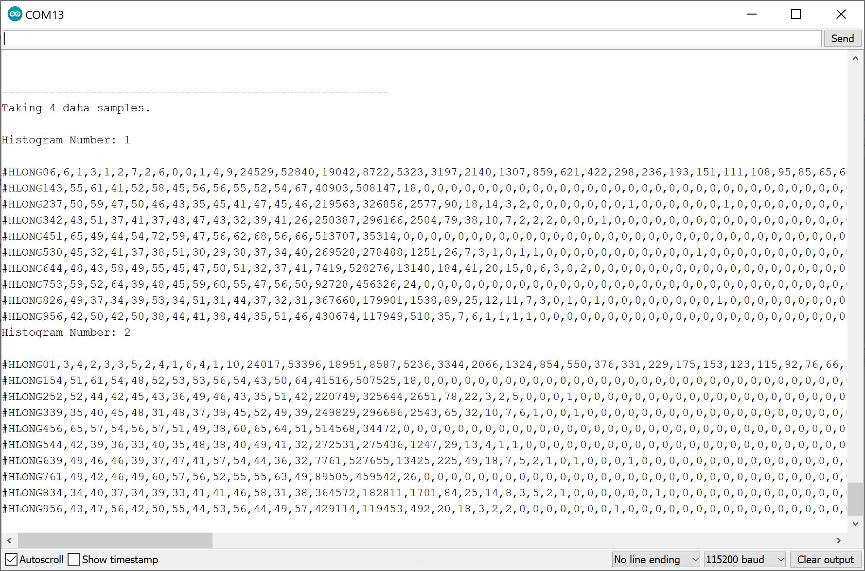
Open the Arduino Serial Monitor at 115200 baud to view the raw histogram data for your TMF8820 and TMF8821. Note that the example code is currently set to take a 4 data samples at a time. You should see an output similar to the image below if you are covering the sensor.
More Examples!
This tutorial highlights a few examples listed in the Arduino Library to get you started. Additional examples can be found in the library.