Qwiic dToF Imager (TMF882X) Hookup Guide
 bboyho,
  Elias The Sparkiest
Hardware Hookup
The following Arduino-compatible processor boards are compatible with the Qwiic dToF TMF8820/TMF8821.
- Artemis
- SAMD21/51
- ESP32
- Teensy
- STM32
- nRF52840
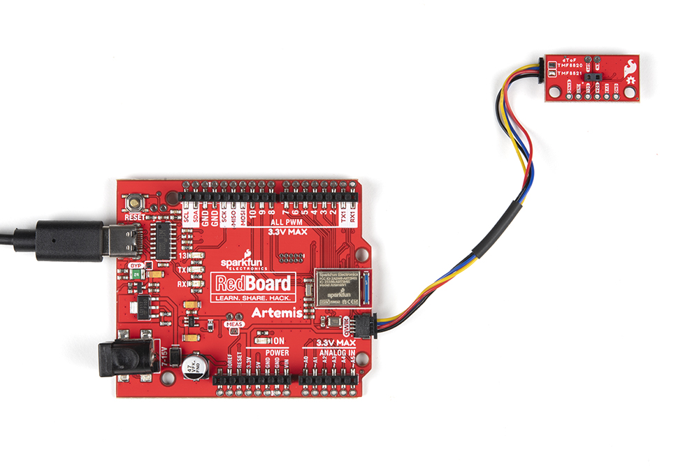
To connect your Qwiic dToF Imager, insert a Qwiic cable between an Arduino-compatible development board and the sensor. Then insert the associated cable for power and programming the microcontroller. In this case, we used the RedBoard Artemis and a USB type C cable. If you're going to be soldering to the through hole pins, then just attach lines to power, ground, and the I2C data lines to the microcontroller of your choice. Make sure to orient the sensor with respect to the TMF8820/TMF8821's SPADs and your application. In this case, the sensor was rotated 90° counterclockwise for reference.

For the Qwiic Mini versions, you would follow the same steps to connect to the sensor. The only difference is that the board is smaller. The image below shows the RedBoard Artemis connecting to the sensor. However, you could use an Arduino-compatible development board that has a smaller form factor. Make sure to orient the sensor with respect to the TMF8820/TMF8821's SPADs and your application.