Qwiic dToF Imager (TMF882X) Hookup Guide
 bboyho,
  Elias The Sparkiest
Hardware Overview
First, let's check out some of the characteristics of the TMF8820 and TMF8821 we're dealing with, so we know what to expect out of the board. Below is a comparison table for both sensors taken from the datasheet. Both are the pretty much the same except for the zone operation. Typically, the each board is powered at 3.3V via the Qwiic connector.
| Characteristic | TMF8820 | TMF8821 |
|---|---|---|
| Operating Voltage | 2.7V to 3.6V, typically 3.3V via Qwiic Connector | |
| I/O Voltage | 1.62V to 3.3V, typically 3.3V via Qwiic Connector | |
| Current Consumption (Standby) | 8µA | |
| Current Consumption (Active) | 57mA | |
| Measurement Range | 10mm to 5000mm, better accuracy detects reliably closest object | |
| Zone Operation | 3x3 | 3x3, 4x4 and 3x6 |
| Light Source | Class 1 940nm VCSEL | |
| I2C Address | 0x41 | |
| Field of View | up to 63° | |
| Max Read Rate | up to 30 Hz | |
| Operating Temperature | -30°C to 70°C | |
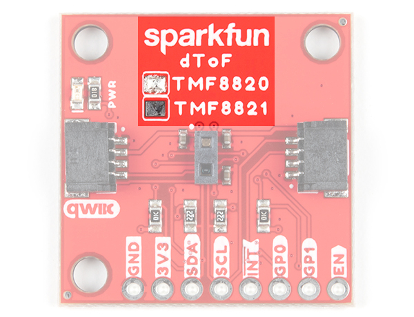
The layout for both the Qwiic dToF Imagers standard and mini sizes are the same. The only difference is the IC that is populated on the boards. The boards can be distinguished by the solder blob on the top side of the board. Below shows the image of the TMF8820 populated boards for the standard and mini size.
 |
 |
| Qwiic dToF Imager - TMF8820/TMF8821 - Label | Qwiic Mini dToF Imager - TMF8820/TMF8821 - Label |
Illuminator and Receiver
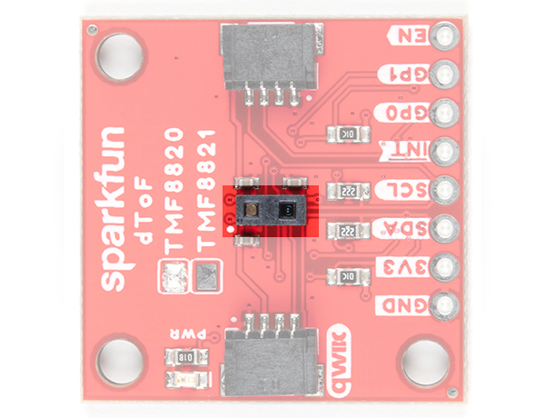
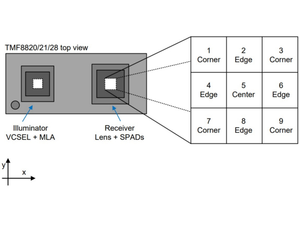
The TMF8820 and TMF8821 consists of an illuminator (VCSEL + MLA) and receiver (lens + SPADs). The illuminator emits a infrared laser at a frequency of 940nm. By taking a smartphone camera or DSLR out, you should be able to see the IR through the illuminator by aiming the camera at an angle when the board is powered and running the example code! The internal processor (ARM M0+ ®) executes the ams algorithm to calculate the target distance of the object.
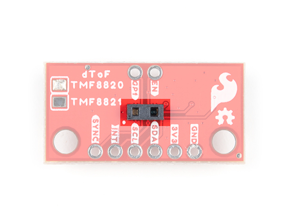
The orientation of the TMF8820/8821 IC's illuminator (VCSEL + MLA) and receiver (lens + SPAD) can be referenced by the IC's polarity marker. You'll need to orient the board based on the marker for your project's needs. While the image below shows the TMF8820, this applies to both the TMF8820 and TMF8821 when using a 3x3 SPAD. The TMF8820 is limited to only a 3x3 SPAD.
 |
 |
 |
| TMF8820 - IC | TMF8820 - IC | 3x3 SPAD Reference spad_map_id=1 (3x3 mode, 33°x32° FoV) |
Below are SPAD map configurations for the 3x3 modes taken from the datasheet. Note that the datasheet recommends that users use the checkerboard SPAD masks for high ambient light conditions.

The orientation of the TMF8821 IC's illuminator (VCSEL + MLA) and receiver (lens + SPAD) can be reference by the IC's polarity marker. You'll need to orient the board based on the marker for your project's needs. The image below shows the TMF8821 and only applies to TMF8821 when using a 4x4 and 3x6 SPAD. The TMF8821 can support a 3x3, 4x4, or 3x6 SPAD. Make sure to configure the IC to set the size of the SPAD.
 |
 |
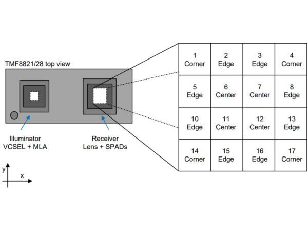 |
| TMF8821 - IC | TMF8821 - IC | TMF8821 - 4x4 SPAD Reference spad_map_id=7 (4x4 mode, 41°x52° FoV) |
Below are SPAD map configurations for the 4x4 and 3x6 modes taken from the datasheet. These configurations are possible with the TMF8821.

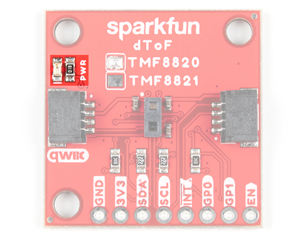
Broken Out Pins
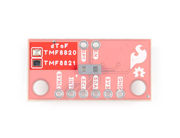
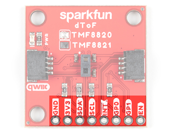
The pins that are broken out are listed out as follows. Note that the pins are rearranged for the Mini version. Most likely you will be using the Qwiic cable to access the sensor. However, you can still solder header pins or wires to the PTHs.
| Pin | Description | Direction |
|---|---|---|
| GND | Ground | In |
| 3.3V | Power | In |
| SDA | Data | In/Out |
| SCL | Clock | In/Out |
| INT | Interrupt, goes low when data is ready. | Out |
| GP0/SYNC | General purpose input/output. This pin can also be used to connect to a SYNC signal to interrupt the TMF8820/TMF8821 if the high power illuminator is operating or sync the sensor to a camera operation. Make sure to not On SYNC assertion, the VCSEL is immediately switched off (typically after 10 µs), on SYNC de-assertion the VCSEL operation is resumed. | In/Out |
| GP1 | General purpose input/output. | In/Out |
| EN | Enable input active high; setting to low forces the device into shutdown and all memory content is lost; this is connected to 3.3V via a 10kΩ pull-up resistor when not being used | In |
 |
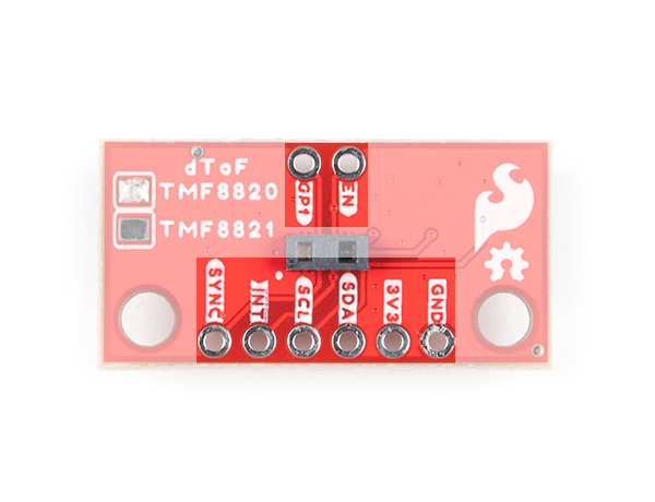 |
| Qwiic dToF Imager - TMF8820/TMF8821 - Breakout Pins | Qwiic Mini dToF Imager - TMF8820/TMF8821 - Breakout Pins |
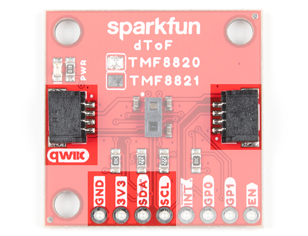
Qwiic and I2C
The breakout boards include 2x Qwiic connectors to easily access the I2C data lines and power. Note that the standard size uses the right angle Qwiic connecgtors The Qwiic ecosystem is made for fast prototyping by removing the need for soldering. All you need to do is plug a Qwiic cable into the Qwiic connector and voila! The I2C address for each sensor is 0x41 as stated earlier.
 |
 |
| Qwiic dToF Imager - TMF8820/TMF8821 | Qwiic Mini dToF Imager - TMF8820/TMF8821 |
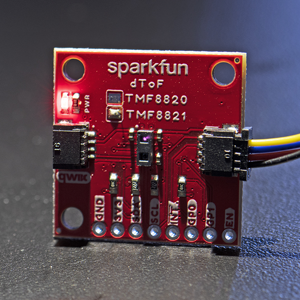
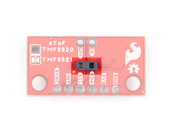
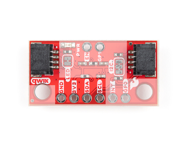
LED
The power LED will light up when the board is powered. To disable, cut the trace on the back of the board.
 |
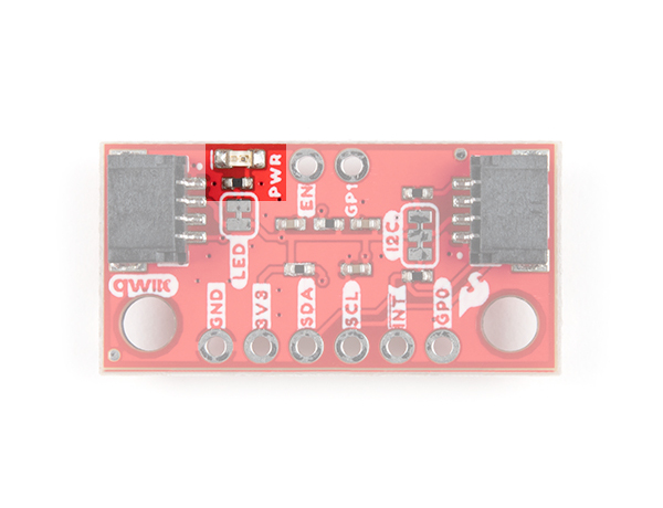 |
| Qwiic dToF Imager - TMF8820/TMF8821 - LED | Qwiic Mini dToF Imager - TMF8820/TMF8821 - LED |
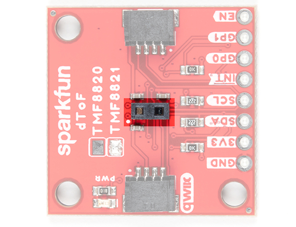
Jumper
There are two jumpers on the back of the board. For more information on modifying the jumpers, check out our tutorial on working with jumper pads and PCB traces.
- I2C - This three way jumper labeled I2C connects two 2.2kΩ pull-up resistors to the I2C data lines by default. If you have many devices on your I2C data lines, then you may consider cutting these.
- LED - This connects to the power LED by default. Cut the trace to disable the LED.
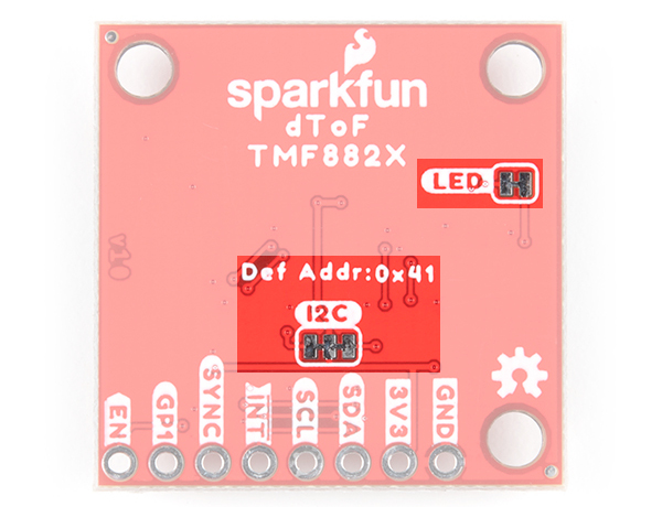 |
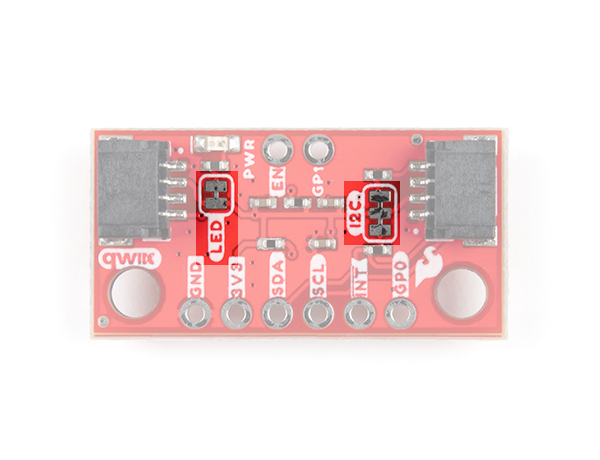 |
| Qwiic dToF Imager - TMF8820/TMF8821 - Jumpers | Qwiic Mini dToF Imager - TMF8820/TMF8821 - Jumpers |
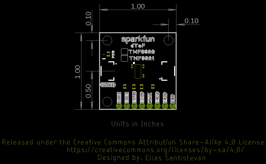
Board Dimensions
The Qwiic dToF Imager TMF8820/TMF8821 use the standard Qwiic size 1.0"x1.0". The mini uses versions has a footprint that is half the size 0.5" x 1.0".
 |
 |
| Qwiic dToF Imager - TMF8820/TMF8821 - Board Dimensions | Qwiic Mini dToF Imager - TMF8820/TMF8821 - Board Dimensions |