Qwiic dToF Imager (TMF882X) Hookup Guide
 bboyho,
  Elias The Sparkiest
 Introduction
The SparkFun Qwiic dToF Imager - TMF8820/TMF8821 are a direct time-of-flight (dToF) sensors that includes single modular package with associated Vertical Cavity Surface Emitting Laser (VCSEL) from AMS. The dToF device is based on Single Photon Avalanche Photodiode (SPAD), time-to-digital converter (TDC) and histogram technology and achieves 5000 mm detection range. Due to its lens on the SPAD, the TMF8820 supports 3x3 multizone output data while the TMF8821 supports 3x3, 4x4, and 3x6 multizone output data. The lens on each dToF Imager provides a very wide, dynamically adjustable, field of view. A multi-lens-array (MLA) inside the package above the VCSEL widens up the FoI (field of illumination). All processing of the raw data is performed on-chip and the TMF8820/TMF8821 provide distance information together with confidence values on its I2C interface. The high performance on-chip optical filter blocks most of the ambient light, and enables distance measurements in dark and sunlight environments.
These sensors are great for projects that such as distance measurement for camera autofocus - Laser Detect Autofocus - LDAF (mobile phone), presence detection (computing and communication), object detection and collision avoidance (robotics), and light curtain (industrial).


Required Materials
To follow along with this tutorial, you will need the following materials. You may not need everything though depending on what you have. Add it to your cart, read through the guide, and adjust the cart as necessary. Note that the following wishlist includes the RedBoard Artemis and the TMF8821. Depending on your application, you can adjust the cart for a different processor board or sensor version.
Suggested Reading
If you aren't familiar with the Qwiic system, we recommend reading here for an overview.
| Qwiic Connect System |
We would also recommend taking a look at the following tutorials if you aren't familiar with them.
Logic Levels
I2C
Hookup Guide for the SparkFun RedBoard Artemis
Installing Board Definitions in the Arduino IDE
Hardware Overview
First, let's check out some of the characteristics of the TMF8820 and TMF8821 we're dealing with, so we know what to expect out of the board. Below is a comparison table for both sensors taken from the datasheet. Both are the pretty much the same except for the zone operation. Typically, the each board is powered at 3.3V via the Qwiic connector.
| Characteristic | TMF8820 | TMF8821 |
|---|---|---|
| Operating Voltage | 2.7V to 3.6V, typically 3.3V via Qwiic Connector | |
| I/O Voltage | 1.62V to 3.3V, typically 3.3V via Qwiic Connector | |
| Current Consumption (Standby) | 8µA | |
| Current Consumption (Active) | 57mA | |
| Measurement Range | 10mm to 5000mm, better accuracy detects reliably closest object | |
| Zone Operation | 3x3 | 3x3, 4x4 and 3x6 |
| Light Source | Class 1 940nm VCSEL | |
| I2C Address | 0x41 | |
| Field of View | up to 63° | |
| Max Read Rate | up to 30 Hz | |
| Operating Temperature | -30°C to 70°C | |
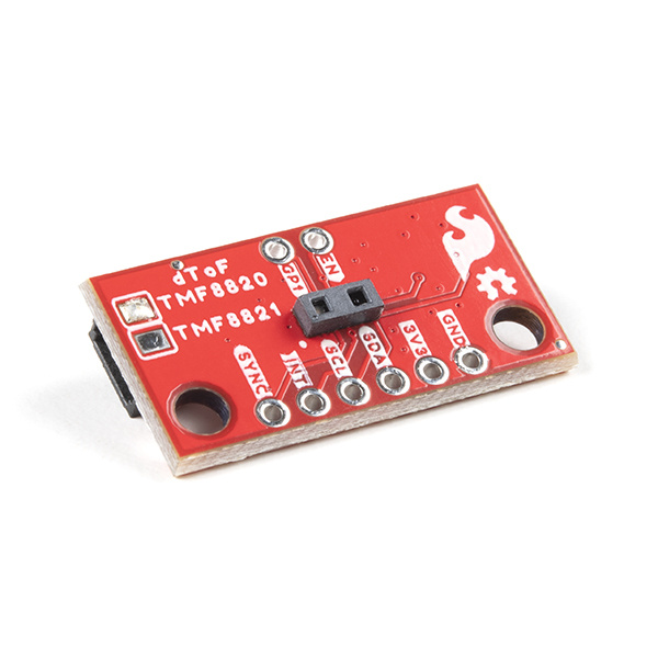
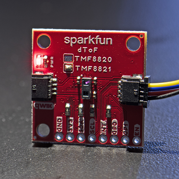
The layout for both the Qwiic dToF Imagers standard and mini sizes are the same. The only difference is the IC that is populated on the boards. The boards can be distinguished by the solder blob on the top side of the board. Below shows the image of the TMF8820 populated boards for the standard and mini size.
 |
 |
| Qwiic dToF Imager - TMF8820/TMF8821 - Label | Qwiic Mini dToF Imager - TMF8820/TMF8821 - Label |
Illuminator and Receiver
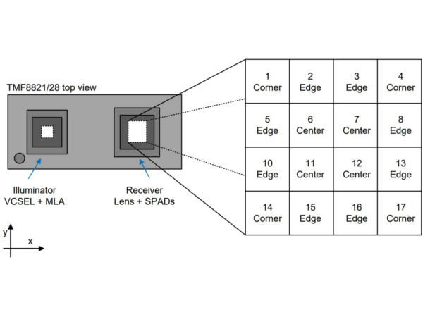
The TMF8820 and TMF8821 consists of an illuminator (VCSEL + MLA) and receiver (lens + SPADs). The illuminator emits a infrared laser at a frequency of 940nm. By taking a smartphone camera or DSLR out, you should be able to see the IR through the illuminator by aiming the camera at an angle when the board is powered and running the example code! The internal processor (ARM M0+ ®) executes the ams algorithm to calculate the target distance of the object.
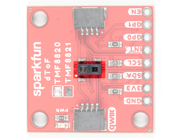
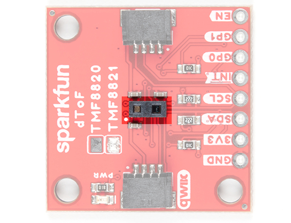
The orientation of the TMF8820/8821 IC's illuminator (VCSEL + MLA) and receiver (lens + SPAD) can be referenced by the IC's polarity marker. You'll need to orient the board based on the marker for your project's needs. While the image below shows the TMF8820, this applies to both the TMF8820 and TMF8821 when using a 3x3 SPAD. The TMF8820 is limited to only a 3x3 SPAD.
 |
 |
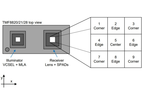 |
| TMF8820 - IC | TMF8820 - IC | 3x3 SPAD Reference spad_map_id=1 (3x3 mode, 33°x32° FoV) |
Below are SPAD map configurations for the 3x3 modes taken from the datasheet. Note that the datasheet recommends that users use the checkerboard SPAD masks for high ambient light conditions.

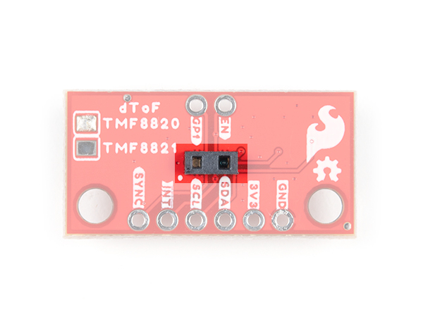
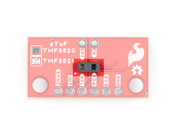
The orientation of the TMF8821 IC's illuminator (VCSEL + MLA) and receiver (lens + SPAD) can be reference by the IC's polarity marker. You'll need to orient the board based on the marker for your project's needs. The image below shows the TMF8821 and only applies to TMF8821 when using a 4x4 and 3x6 SPAD. The TMF8821 can support a 3x3, 4x4, or 3x6 SPAD. Make sure to configure the IC to set the size of the SPAD.
 |
 |
 |
| TMF8821 - IC | TMF8821 - IC | TMF8821 - 4x4 SPAD Reference spad_map_id=7 (4x4 mode, 41°x52° FoV) |
Below are SPAD map configurations for the 4x4 and 3x6 modes taken from the datasheet. These configurations are possible with the TMF8821.

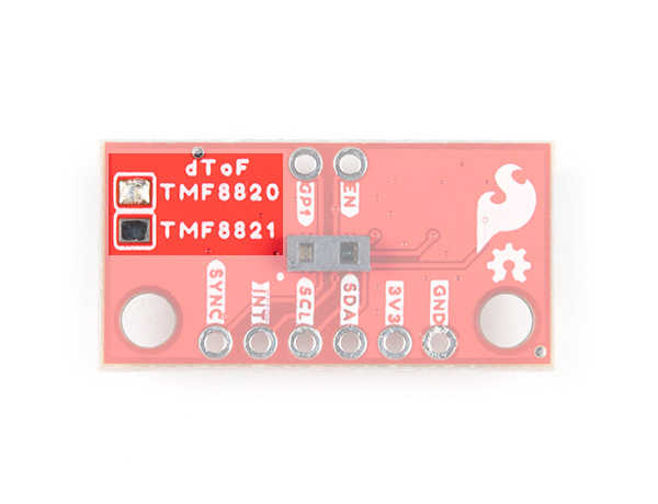
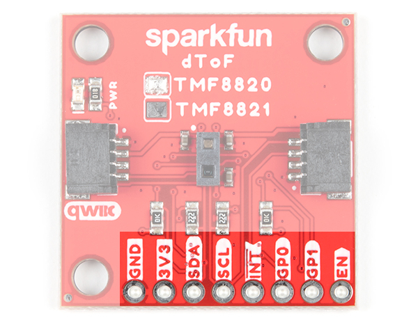
Broken Out Pins
The pins that are broken out are listed out as follows. Note that the pins are rearranged for the Mini version. Most likely you will be using the Qwiic cable to access the sensor. However, you can still solder header pins or wires to the PTHs.
| Pin | Description | Direction |
|---|---|---|
| GND | Ground | In |
| 3.3V | Power | In |
| SDA | Data | In/Out |
| SCL | Clock | In/Out |
| INT | Interrupt, goes low when data is ready. | Out |
| GP0/SYNC | General purpose input/output. This pin can also be used to connect to a SYNC signal to interrupt the TMF8820/TMF8821 if the high power illuminator is operating or sync the sensor to a camera operation. Make sure to not On SYNC assertion, the VCSEL is immediately switched off (typically after 10 µs), on SYNC de-assertion the VCSEL operation is resumed. | In/Out |
| GP1 | General purpose input/output. | In/Out |
| EN | Enable input active high; setting to low forces the device into shutdown and all memory content is lost; this is connected to 3.3V via a 10kΩ pull-up resistor when not being used | In |
 |
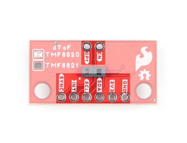 |
| Qwiic dToF Imager - TMF8820/TMF8821 - Breakout Pins | Qwiic Mini dToF Imager - TMF8820/TMF8821 - Breakout Pins |
Qwiic and I2C
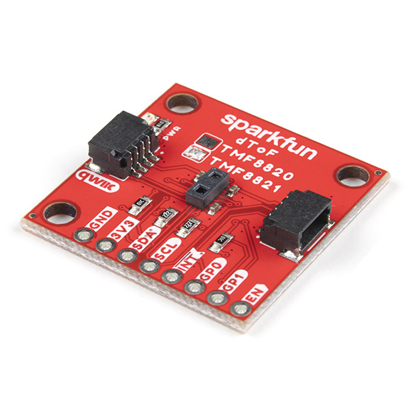
The breakout boards include 2x Qwiic connectors to easily access the I2C data lines and power. Note that the standard size uses the right angle Qwiic connecgtors The Qwiic ecosystem is made for fast prototyping by removing the need for soldering. All you need to do is plug a Qwiic cable into the Qwiic connector and voila! The I2C address for each sensor is 0x41 as stated earlier.
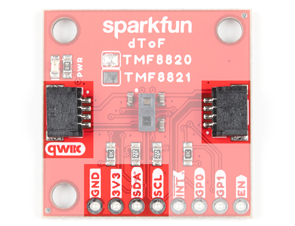 |
 |
| Qwiic dToF Imager - TMF8820/TMF8821 | Qwiic Mini dToF Imager - TMF8820/TMF8821 |
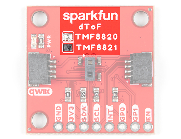
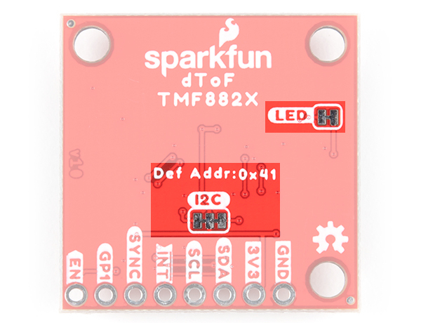
LED
The power LED will light up when the board is powered. To disable, cut the trace on the back of the board.
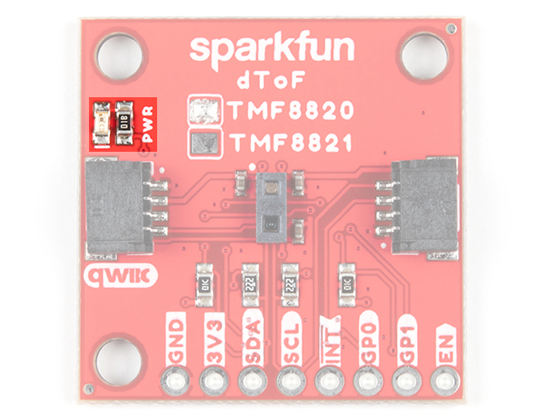 |
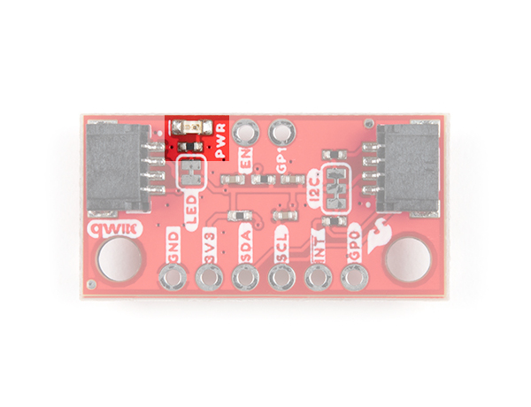 |
| Qwiic dToF Imager - TMF8820/TMF8821 - LED | Qwiic Mini dToF Imager - TMF8820/TMF8821 - LED |
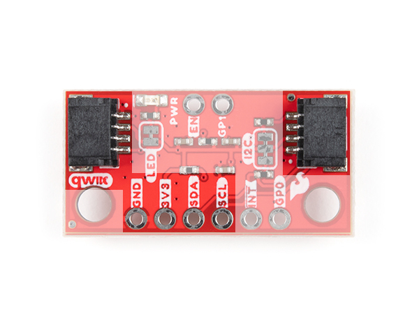
Jumper
There are two jumpers on the back of the board. For more information on modifying the jumpers, check out our tutorial on working with jumper pads and PCB traces.
- I2C - This three way jumper labeled I2C connects two 2.2kΩ pull-up resistors to the I2C data lines by default. If you have many devices on your I2C data lines, then you may consider cutting these.
- LED - This connects to the power LED by default. Cut the trace to disable the LED.
 |
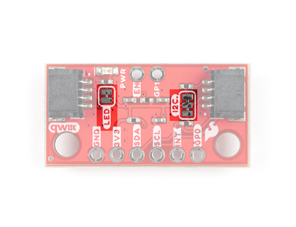 |
| Qwiic dToF Imager - TMF8820/TMF8821 - Jumpers | Qwiic Mini dToF Imager - TMF8820/TMF8821 - Jumpers |
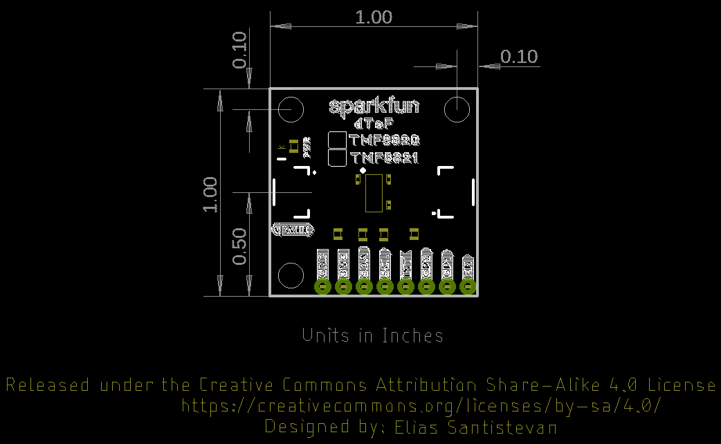
Board Dimensions
The Qwiic dToF Imager TMF8820/TMF8821 use the standard Qwiic size 1.0"x1.0". The mini uses versions has a footprint that is half the size 0.5" x 1.0".
 |
 |
| Qwiic dToF Imager - TMF8820/TMF8821 - Board Dimensions | Qwiic Mini dToF Imager - TMF8820/TMF8821 - Board Dimensions |
Hardware Hookup
The following Arduino-compatible processor boards are compatible with the Qwiic dToF TMF8820/TMF8821.
- Artemis
- SAMD21/51
- ESP32
- Teensy
- STM32
- nRF52840
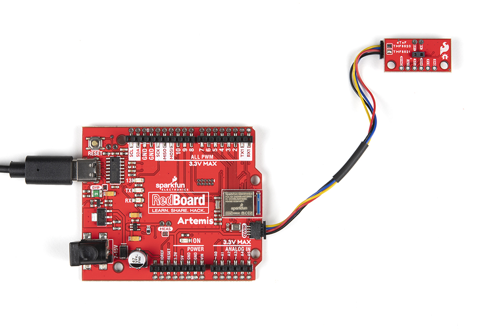
To connect your Qwiic dToF Imager, insert a Qwiic cable between an Arduino-compatible development board and the sensor. Then insert the associated cable for power and programming the microcontroller. In this case, we used the RedBoard Artemis and a USB type C cable. If you're going to be soldering to the through hole pins, then just attach lines to power, ground, and the I2C data lines to the microcontroller of your choice. Make sure to orient the sensor with respect to the TMF8820/TMF8821's SPADs and your application. In this case, the sensor was rotated 90° counterclockwise for reference.

For the Qwiic Mini versions, you would follow the same steps to connect to the sensor. The only difference is that the board is smaller. The image below shows the RedBoard Artemis connecting to the sensor. However, you could use an Arduino-compatible development board that has a smaller form factor. Make sure to orient the sensor with respect to the TMF8820/TMF8821's SPADs and your application.
Software Installation
- Installing the Arduino IDE
- Installing an Arduino Library
- Installing Board Definitions in the Arduino IDE
If you've never connected an CH340 device to your computer before, you may need to install drivers for the USB-to-serial converter. Check out our section on How to Install CH340 Drivers" for help with the installation.
The SparkFun TMF882X dToF Arduino library can be downloaded with the Arduino library manager by searching 'SparkFun TMF882X dToF Arduino Library' or you can grab the zip here from the GitHub repository to manually install:
Arduino Examples
Below are a few examples that are highlighted from the Arduino library.
Example 1: Basic
The following example uses the RedBoard Artemis. However, you could also use any Arduino-compatible microcontroller listed earlier in this tutorial if it has enough memory.
After installing the library, open the sketch in Arduino: File > Examples > SparkFun Qwiic TMF882X Arduino Library > Example-01_Basic. The following code was copied from the Arduino Library for your convenience. If you have not already, select your Board (in this case the RedBoard Artemis), and associated COM port. Upload the code to the board.
language:c
/*

  Example-01_Basic.ino

  This demo shows a basic use of a TMF882X device. The device is connected to,
  and a single reading is taken for each loop iteration.

  Supported Boards:

   SparkFun Qwiic dToF Imager - TMF8820        https://www.sparkfun.com/products/19036
   SparkFun Qwiic Mini dToF Imager - TMF8820   https://www.sparkfun.com/products/19218
   SparkFun Qwiic Mini dToF Imager - TMF8821   https://www.sparkfun.com/products/19451
   SparkFun Qwiic dToF Imager - TMF8821        https://www.sparkfun.com/products/19037

  Written by Kirk Benell @ SparkFun Electronics, April 2022

  Repository:
     https://github.com/sparkfun/SparkFun_Qwiic_TMF882X_Arduino_Library

  Documentation:
     https://sparkfun.github.io/SparkFun_Qwiic_TMF882X_Arduino_Library/

  SparkFun code, firmware, and software is released under the MIT License(http://opensource.org/licenses/MIT).
*/

#include "SparkFun_TMF882X_Library.h" //http://librarymanager/All#SparkFun_Qwiic_TMPF882X

SparkFun_TMF882X  myTMF882X;

// Structure to hold the measurement results - this is defined by the TMF882X SDK.

static struct tmf882x_msg_meas_results myResults;

void setup()
{

    delay(1000);
    Serial.begin(115200);
    Serial.println("");

    Serial.println("In setup");
    Serial.println("==============================");

    // Initialize the TMF882X device
    if(!myTMF882X.begin())
    {
        Serial.println("Error - The TMF882X failed to initialize - is the board connected?");
        while(1);
    }else
        Serial.println("TMF882X started.");

    // The device is now ready for operations
}

void loop()
{
    delay(2000);

    // get a Measurement
    if(myTMF882X.startMeasuring(myResults))
    {
        // print out results
        Serial.println("Measurement:");
        Serial.print("     Result Number: "); Serial.print(myResults.result_num);
        Serial.print("  Number of Results: "); Serial.println(myResults.num_results);

        for (int i = 0; i < myResults.num_results; ++i)
        {
            Serial.print("       conf: "); Serial.print(myResults.results[i].confidence);
            Serial.print(" distance mm: "); Serial.print(myResults.results[i].distance_mm);
            Serial.print(" channel: "); Serial.print(myResults.results[i].channel);
            Serial.print(" sub_capture: "); Serial.println(myResults.results[i].sub_capture);

        }
        Serial.print("     photon: "); Serial.print(myResults.photon_count);
        Serial.print(" ref photon: "); Serial.print(myResults.ref_photon_count);
        Serial.print(" ALS: "); Serial.println(myResults.ambient_light); Serial.println();

    }

}
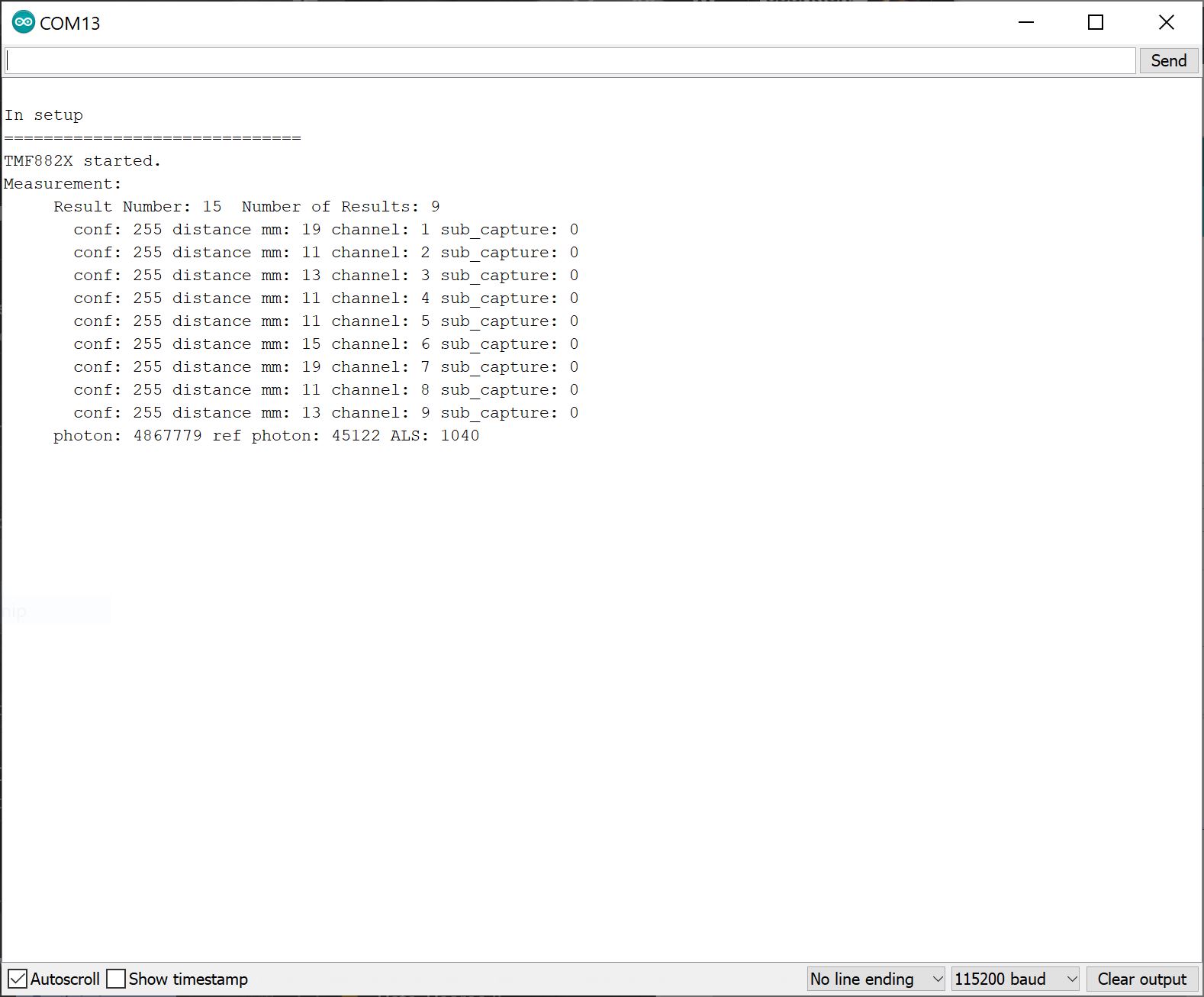
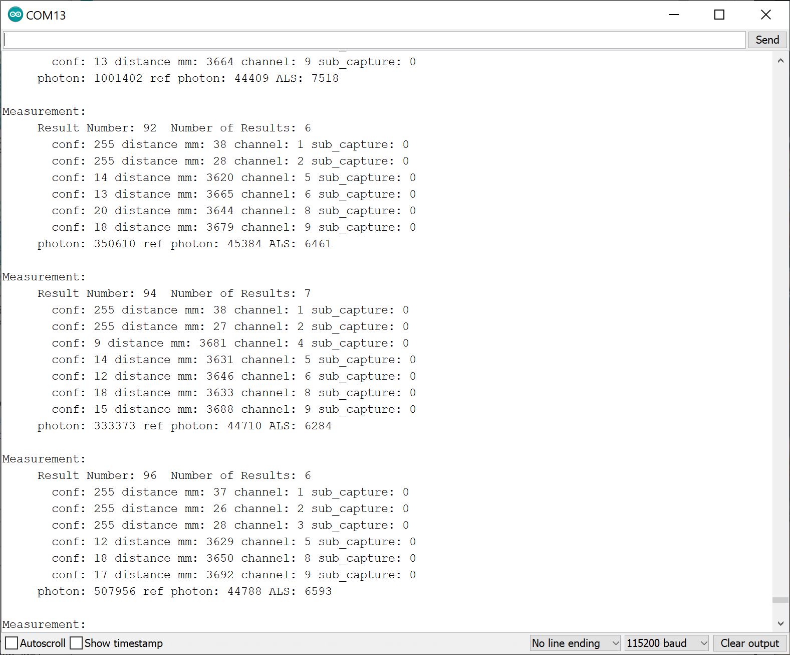
Open the Arduino Serial Monitor set to 115200 baud. Place an object like your finger or a flat, rigid object in front of the dToF Imager's IC. You should see something similar in the output below. The readings show a high confidence value [.confidence values are between 0 and 255, with 255 being the highest] and the distance measurements in millimeters [.distance_mm] for each channel [.channel]. The output also provides information about the total photons received [.photon_count], reference photon [.ref_photon_count], and tutorial ambient light [.ambient_light]received by the channels.
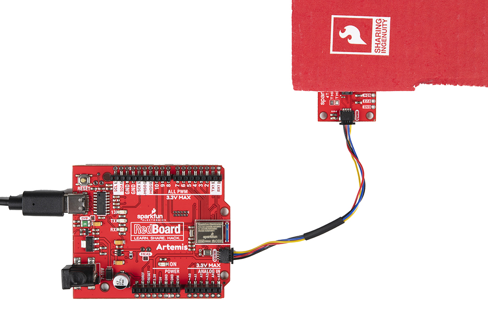
Try positioning the object so that channel 1 through 3 is covered and close to the TMF8820/TMF8821. In this case, we used a piece of cardboard to partially cover the sensor. Make sure to orient the board with respect to the SPADs as shown in the image below to easily view the changes in the output.
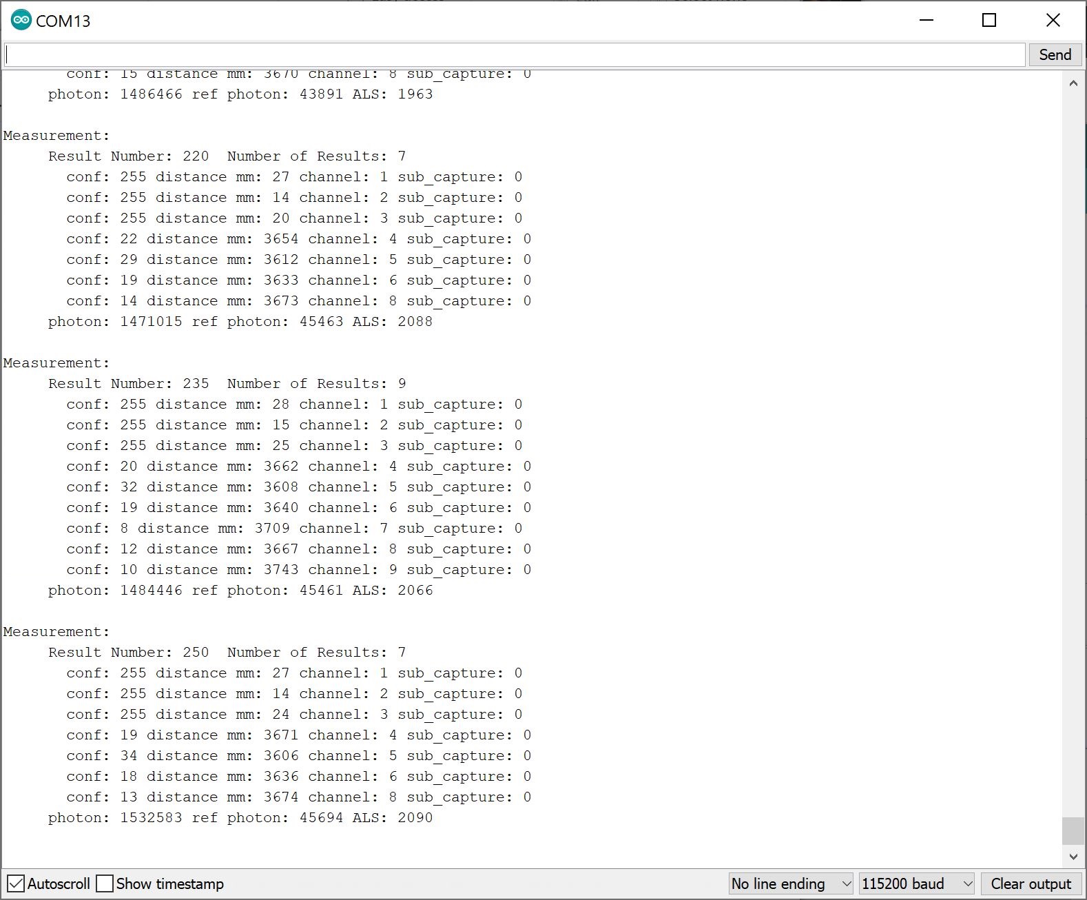
With the Serial Monitor still open, you should see something similar to the output below. You will notice that the sensor was able to detect an object over channels 1 through 3 with a high confidence. The values for the other channels that were not covered by the cardboard showed a low confidence and longer distance values, which were close to the distance between the top of my desk and the ceiling (i.e. 12 feet). The TMF8820/TMF8821 may not display a result if the SPAD does not receive a reflected pulse.
Example 5: Verbose
With the library installed, open the sketch in Arduino: File > Examples > SparkFun Qwiic TMF882X Arduino Library > Example-05_Verbose. The following code was copied from the Arduino Library for your convenience. If you have not already, select your Board (in this case the RedBoard Artemis), and associated COM port. Upload the code to the board.
language:c
/*

  Example-05_Verbose.ino

  The TMF882X Arduino library uses the TMF882X Software Development Kit (SDK) from
  AMS to interface with the sensor.

  The AMS SDK is able to print out informational messages during normal operation, as
  well as debug messages. This example shows how to enable those messages and direct
  them to a Serial device for output.

  Supported Boards:

   SparkFun Qwiic dToF Imager - TMF8820        https://www.sparkfun.com/products/19036
   SparkFun Qwiic Mini dToF Imager - TMF8820   https://www.sparkfun.com/products/19218
   SparkFun Qwiic Mini dToF Imager - TMF8821   https://www.sparkfun.com/products/19451
   SparkFun Qwiic dToF Imager - TMF8821        https://www.sparkfun.com/products/19037

  Written by Kirk Benell @ SparkFun Electronics, April 2022

  Repository:
     https://github.com/sparkfun/SparkFun_Qwiic_TMF882X_Arduino_Library

  Documentation:
     https://sparkfun.github.io/SparkFun_Qwiic_TMF882X_Arduino_Library/

  SparkFun code, firmware, and software is released under the MIT License(http://opensource.org/licenses/MIT).
*/

#include "SparkFun_TMF882X_Library.h"    //http://librarymanager/All#SparkFun_Qwiic_TMPF882X

SparkFun_TMF882X  myTMF882X;

static struct tmf882x_msg_meas_results myResults;

void setup()
{

    delay(1000);
    Serial.begin(115200);
    Serial.println("");

    Serial.println("In setup");
    Serial.println("==============================");

    // The underlying TMF882X SDK can output a wide variety of information during
    // normal operation. It's very verbose.
    //
    // Enable this output as part of this demo.
    //
    // Pass in our output device - Serial

    myTMF882X.setOutputDevice(Serial);

    // Enable Info messages
    myTMF882X.setInfoMessages(true);

    // Enable Debug mode. Set this before calling begin to get initialization debug
    // information.

    myTMF882X.setDebug(true);

    if(!myTMF882X.begin())
    {
        Serial.println("Error - The TMF882X failed to initialize - is the board connected?");
        while(1);
    }else
        Serial.println("TMF882X started.");


}

void loop()
{
    delay(2000);

    // get a myResultsurment
    if(myTMF882X.startMeasuring(myResults))
    {
        // print out results
        Serial.println("Measurement:");
        Serial.print("     Result Number: "); Serial.print(myResults.result_num);
        Serial.print("  Number of Results: "); Serial.println(myResults.num_results);

        for (uint32_t i = 0; i < myResults.num_results; ++i)
        {
            Serial.print("       conf: "); Serial.print(myResults.results[i].confidence);
            Serial.print(" distance mm: "); Serial.print(myResults.results[i].distance_mm);
            Serial.print(" channel: "); Serial.print(myResults.results[i].channel);
            Serial.print(" sub_capture: "); Serial.println(myResults.results[i].sub_capture);

        }
        Serial.print("     photon: "); Serial.print(myResults.photon_count);
        Serial.print(" ref photon: "); Serial.print(myResults.ref_photon_count);
        Serial.print(" ALS: "); Serial.println(myResults.ambient_light); Serial.println();

    }

}
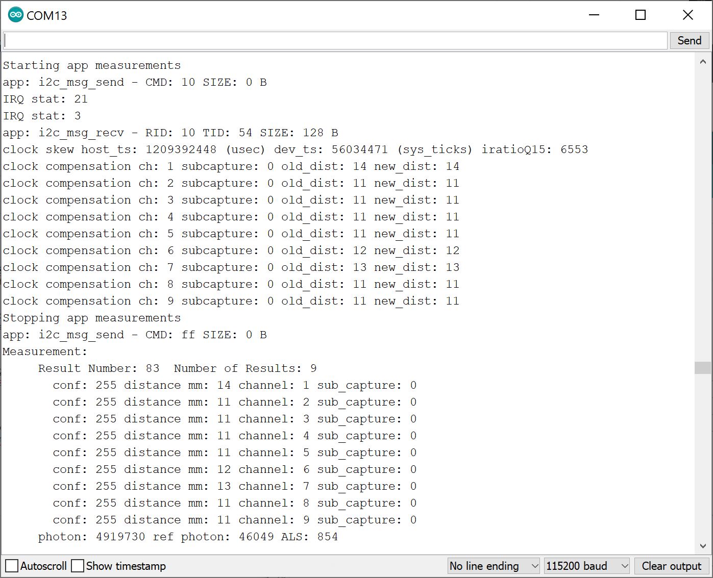
Open the Arduino Serial Monitor set to 115200 baud. The output is similar to the Basic example. However, there is additional information displayed. This information is useful for those debugging with the TMF8820 or TMF8821. The measurements were taken when an object was covering the IC completely.
Example 8: Factory Calibration
This example is suggested when placing the TMF8820 and TMF8821 its final application and when adjusting the SPAD mask selection. As suggested in the datasheet under 7.3 Calibration, "the calibration test shall be done in a housing with minimal ambient light and no target within 40 cm in field of view of the TMF8820/21."
With the library installed, open the sketch in Arduino: File > Examples > SparkFun Qwiic TMF882X Arduino Library > Example-08_FactoryCal. The following code was copied from the Arduino Library for your convenience. If you have not already, select your Board (in this case the RedBoard Artemis), and associated COM port. Upload the code to the board.
language:c
/*

  Example-08_FactoryCal.ino

  This example shows how to peform a Factory Calibration on the connected
  TMF882X device. Details on the calibration and it's use are contained in
  the TMF882X datasheet.

  Supported Boards:

   SparkFun Qwiic dToF Imager - TMF8820        https://www.sparkfun.com/products/19036
   SparkFun Qwiic Mini dToF Imager - TMF8820   https://www.sparkfun.com/products/19218
   SparkFun Qwiic Mini dToF Imager - TMF8821   https://www.sparkfun.com/products/19451
   SparkFun Qwiic dToF Imager - TMF8821        https://www.sparkfun.com/products/19037

  Written by Kirk Benell @ SparkFun Electronics, April 2022

  Repository:
     https://github.com/sparkfun/SparkFun_Qwiic_TMF882X_Arduino_Library

  Documentation:
     https://sparkfun.github.io/SparkFun_Qwiic_TMF882X_Arduino_Library/

  SparkFun code, firmware, and software is released under the MIT License(http://opensource.org/licenses/MIT).
*/


#include <SparkFun_TMF882X_Library.h>    //http://librarymanager/All#SparkFun_Qwiic_TMPF882X

SparkFun_TMF882X  myTMF882X;

void setup()
{

    delay(1000);
    Serial.begin(115200);
    Serial.println("");

    Serial.println("In setup");
    Serial.println("==============================");

    if(!myTMF882X.begin())
    {
        Serial.println("Error - The TMF882X failed to initialize - is the board connected?");
        while(1){}
    }else
        Serial.println("TMF882X started.");


    Serial.println();
    Serial.println("Performing a Factory Calibration.");
    Serial.println();
    // Perform a factory calibration of the connected device.

    // First set some config parameters to support the calibration
    struct tmf882x_mode_app_config tofConfig;
    if (!myTMF882X.getTMF882XConfig(tofConfig))
    {
        Serial.println("Error - unable to get device configuration.");
        while(1){}
    }

    // Change the APP configuration
    //  - set the reporting period to 500 milliseconds
    //  - set the iterations to 4,000,000 (4M) to perform factory calibration
    tofConfig.report_period_ms = 500;
    tofConfig.kilo_iterations = 4000;

    if (!myTMF882X.setTMF882XConfig(tofConfig))
    {
        Serial.println("Error - unable to set device configuration.");
        while(1){}
    }

    struct tmf882x_mode_app_calib factoryCal;

    // Peform the calibration
    if (!myTMF882X.factoryCalibration(factoryCal))
    {
        Serial.println("Error - Factory Calibration Failed.");
        while(1){}
    }

    // Output the calibration
    Serial.println("Calibration Complete");
    Serial.println();
    Serial.print("Calibration Data Length: ");
    Serial.println(factoryCal.calib_len);

    Serial.println("Calibration Data:");
    for (int i = 0; i < factoryCal.calib_len; i++)
    {
        Serial.print("   "); Serial.print(factoryCal.data[i]);

        if ( (i + 1) % 16 == 0 )
            Serial.println();
    }
    Serial.println();

}

void loop()
{
    delay(2000);

    // Nothing - just here for the calibration example
}
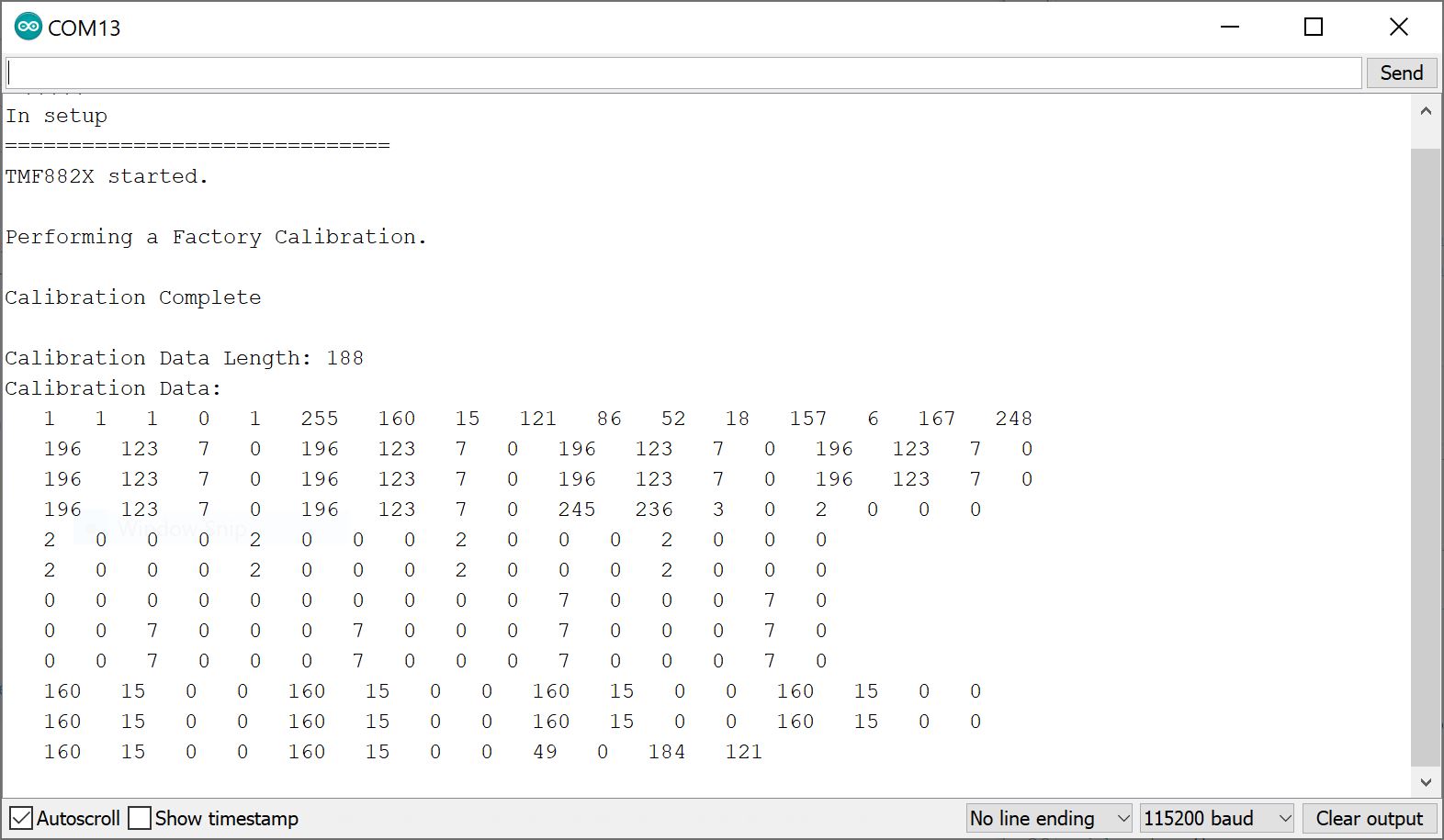
Open the Arduino Serial Monitor set to 115200 baud. You will see an output similar to the image below. You will need to follow the datasheet to calibrate the sensor properly.
Example 9: SPAD Map
SPAD_MAP_ID each time the TMF8820/TMF8821 is powered up. Make sure to also calibrate the sensor after adjusting the SPAD map.
With the library installed, open the sketch in Arduino: File > Examples > SparkFun Qwiic TMF882X Arduino Library > Example-09_SPADMap. The following code was copied from the Arduino Library for your convenience. If you have not already, select your Board (in this case the RedBoard Artemis), and associated COM port. Upload the code to the board.
language:c
/*

  Example-09_SPADMap.ino

  The Optical performance of the TMF882X is controled by a SPAD (Single Photon
  Avalanche Photodiode) Map.

  SPAD Maps are set using a SPAD Map ID, which are detailed in the TMF882X datasheet.

  This example shows how to determine the current SPAD Map on the device and change
  it to a desired map.

  Supported Boards:

   SparkFun Qwiic dToF Imager - TMF8820        https://www.sparkfun.com/products/19036
   SparkFun Qwiic Mini dToF Imager - TMF8820   https://www.sparkfun.com/products/19218
   SparkFun Qwiic Mini dToF Imager - TMF8821   https://www.sparkfun.com/products/19451
   SparkFun Qwiic dToF Imager - TMF8821        https://www.sparkfun.com/products/19037

  Written by Kirk Benell @ SparkFun Electronics, April 2022

  Repository:
     https://github.com/sparkfun/SparkFun_Qwiic_TMF882X_Arduino_Library

  Documentation:
     https://sparkfun.github.io/SparkFun_Qwiic_TMF882X_Arduino_Library/

  SparkFun code, firmware, and software is released under the MIT License(http://opensource.org/licenses/MIT).
*/

#include <SparkFun_TMF882X_Library.h>    //http://librarymanager/All#SparkFun_Qwiic_TMPF882X

static struct tmf882x_msg_meas_results myResults;


SparkFun_TMF882X  myTMF882X;

// What SPAD map to change to

#define NEW_SPAD_MAP 2

void setup()
{

    delay(1000);
    Serial.begin(115200);
    Serial.println("");

    Serial.println("In setup");
    Serial.println("==============================");

    if(!myTMF882X.begin())
    {
        Serial.println("Error - The TMF882X failed to initialize - is the board connected?");
        while(1){}
    }else
        Serial.println("TMF882X started.");


    // Let's change the SPAD map in use on this device.
    //
    // Get the current SPAD Map ID
    int spadMap =  myTMF882X.getCurrentSPADMap();
    Serial.println();
    Serial.print("Current SPAD Map ID: ");
    Serial.println(spadMap);

    // Now switch
    Serial.println("Switching SPAD Map to ID 2 - 3x3 Macro 1 off center");
    Serial.println();

    if (!myTMF882X.setCurrentSPADMap(NEW_SPAD_MAP))
    {
        Serial.println("Error -  Failed to set the SPAD Map - halting");
        while(1){}
    }

    // Let's make sure it worked
    spadMap =  myTMF882X.getCurrentSPADMap();

    if(spadMap != NEW_SPAD_MAP)
    {
        Serial.println("Error -  Failed to set the SPAD Map - halting");
        while(1){}
    }

    Serial.print("The new SPAD Map ID: ");
    Serial.println(spadMap);

    // Now set some config parameters to support the spad map
    struct tmf882x_mode_app_config tofConfig;

    if (!myTMF882X.getTMF882XConfig(tofConfig))
    {
        Serial.println("Error - unable to get device configuration.");
        while(1){}
    }

    // Change the APP configuration
    //  - set the reporting period to 500 milliseconds
    tofConfig.report_period_ms = 500;

    if (!myTMF882X.setTMF882XConfig(tofConfig))
    {
        Serial.println("Error - unable to set device configuration.");
        while(1){}
    }

}

void loop()
{
    delay(2000);

    // get a myResultsurment
    if(myTMF882X.startMeasuring(myResults))
    {
        // print out results
        Serial.println("Measurement:");
        Serial.print("     Result Number: "); Serial.print(myResults.result_num);
        Serial.print("  Number of Results: "); Serial.println(myResults.num_results);

        for (int i = 0; i < myResults.num_results; ++i)
        {
            Serial.print("       conf: "); Serial.print(myResults.results[i].confidence);
            Serial.print(" distance mm: "); Serial.print(myResults.results[i].distance_mm);
            Serial.print(" channel: "); Serial.print(myResults.results[i].channel);
            Serial.print(" sub_capture: "); Serial.println(myResults.results[i].sub_capture);

        }
        Serial.print("     photon: "); Serial.print(myResults.photon_count);
        Serial.print(" ref photon: "); Serial.print(myResults.ref_photon_count);
        Serial.print(" ALS: "); Serial.println(myResults.ambient_light); Serial.println();

    }
}
This example allows you to select the operating mode of the SPAD. The datasheet under "8.5.17 SPAD_MAP_ID Register" provides a list of acceptable values and modes. Note that certain values are reserved and zone configurations may not be available to use for the TMF8820 (i.e. limited to 3x3) or TMF8821 (i.e. limited to 3x3, 4x4, 3x6).
Once uploaded, open the Arduino Serial Monitor at 115200 baud and cover channels 1 through 3. The spad_map_id was changed to 2. The readings are similar to example 1 when the SPAD was using the default 3x3 Normal Mode. However, SPAD uses a different FOV and slightly offset.
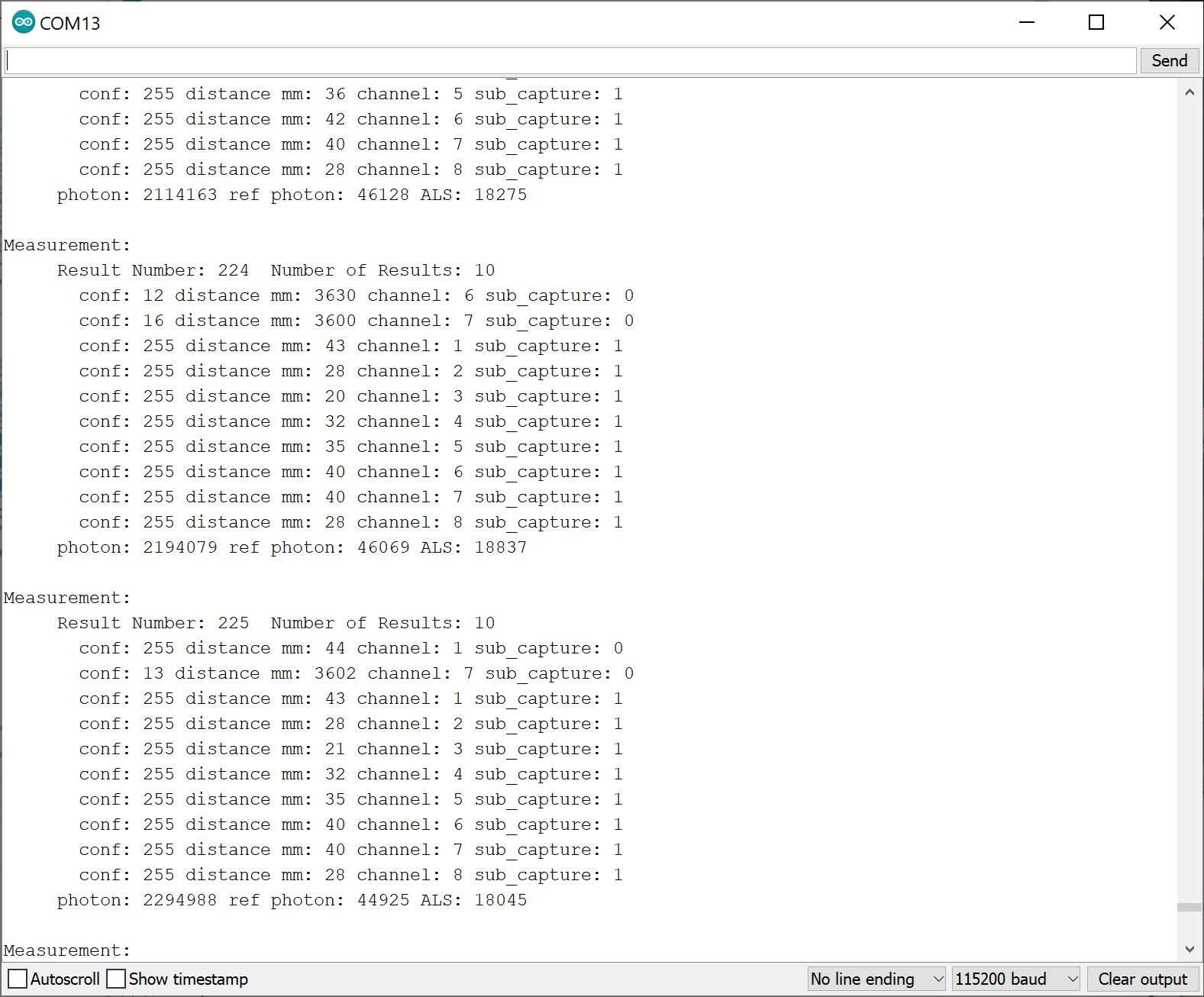
If you have a TMF8821, try adjusting the SPAD to 4x4 normal mode with a 41°x52° FoV by changing spad_map_id to 7 (i.e. change the line #define NEW_SPAD_MAP 2 to #define NEW_SPAD_MAP 7). Then upload the code to the board.
Open the Arduino Serial Monitor at 115200 baud and try to cover channels 9 through 16. You will see an output similar to the image below indicating that the respective channels were covered.
Example 11: Histogram
With the library installed, open the sketch in Arduino: File > Examples > SparkFun Qwiic TMF882X Arduino Library > Example-11_Histogram. The following code was copied from the Arduino Library for your convenience. If you have not already, select your Board (in this case the RedBoard Artemis), and associated COM port. Upload the code to the board.
language:c
/*

  Example-11_Histogram.ino

  This example shows how to enable and recieve raw histogram data from the
  connected TMF882X device

  Supported Boards:

   SparkFun Qwiic dToF Imager - TMF8820        https://www.sparkfun.com/products/19036
   SparkFun Qwiic Mini dToF Imager - TMF8820   https://www.sparkfun.com/products/19218
   SparkFun Qwiic Mini dToF Imager - TMF8821   https://www.sparkfun.com/products/19451
   SparkFun Qwiic dToF Imager - TMF8821        https://www.sparkfun.com/products/19037

  Written by Kirk Benell @ SparkFun Electronics, April 2022

  Repository:
     https://github.com/sparkfun/SparkFun_Qwiic_TMF882X_Arduino_Library

  Documentation:
     https://sparkfun.github.io/SparkFun_Qwiic_TMF882X_Arduino_Library/

  SparkFun code, firmware, and software is released under the MIT License(http://opensource.org/licenses/MIT).
*/

#include "SparkFun_TMF882X_Library.h"  //http://librarymanager/All#SparkFun_Qwiic_TMPF882X

SparkFun_TMF882X  myTMF882X;

#define NUMBER_OF_SAMPLES_TO_TAKE  4

int nSample = 0;

// For our histogram printout
#define MAX_BIN_LEN 128

// Define our histogram callback function

void onHistogramCallback(struct tmf882x_msg_histogram *myHistogram)
{

    nSample++;

    Serial.print("Histogram Number: ");
    Serial.println(nSample);

    uint8_t zone_count = 0;
    for (int tdc_idx = 0; tdc_idx < myHistogram->num_tdc; ++tdc_idx)
    {
        // Histogram tag for zones, #HLONG01,#HLONG02....
        Serial.println();
        Serial.print("#HLONG");
        Serial.print(zone_count++);

        for (int bin_idx = 0; bin_idx < myHistogram->num_bins; ++bin_idx) {

            Serial.print((unsigned long)myHistogram->bins[tdc_idx][bin_idx]);

            if ((bin_idx + 1) == MAX_BIN_LEN)
            {
                Serial.println();
                Serial.print("#HLONG");
                Serial.print(zone_count++);

            } else if ((bin_idx + 1) % MAX_BIN_LEN != 0)
                Serial.print(",");
        }
    }
    Serial.println();
}

void setup()
{

    delay(500);
    Serial.begin(115200);
    Serial.println("");


    if(!myTMF882X.begin())
    {
        Serial.println("Error - The TMF882X failed to initialize - is the board connected?");
        while(1){}
    }

    // set our call back function that handles histograms
    myTMF882X.setHistogramHandler(onHistogramCallback);

    // Set our delay between samples  - 1 second - note it's in ms
    myTMF882X.setSampleDelay(1000);

    // First config parameter to enable output of histogram data.

    struct tmf882x_mode_app_config tofConfig;
    if (!myTMF882X.getTMF882XConfig(tofConfig))
    {
        Serial.println("Error - unable to get device configuration.");
        while(1){}
    }

    // Change the APP configuration
    //  - set the reporting period to 500 milliseconds
    //  - Enable Histogram mode
    tofConfig.report_period_ms = 500;
    tofConfig.histogram_dump = 1;

    if (!myTMF882X.setTMF882XConfig(tofConfig))
    {
        Serial.println("Error - unable to set device configuration.");
        while(1){}
    }
}

void loop()
{
    delay(2000);

    // get a measurment
    // Have the sensor take 4 measurements, the results are sent to the above callback

    Serial.println("---------------------------------------------------------");
    Serial.print("Taking ");
    Serial.print(NUMBER_OF_SAMPLES_TO_TAKE);
    Serial.println(" data samples.");
    Serial.println();

    nSample=0;
    myTMF882X.startMeasuring(NUMBER_OF_SAMPLES_TO_TAKE);

    Serial.println("---------------------------------------------------------\n\n");

}
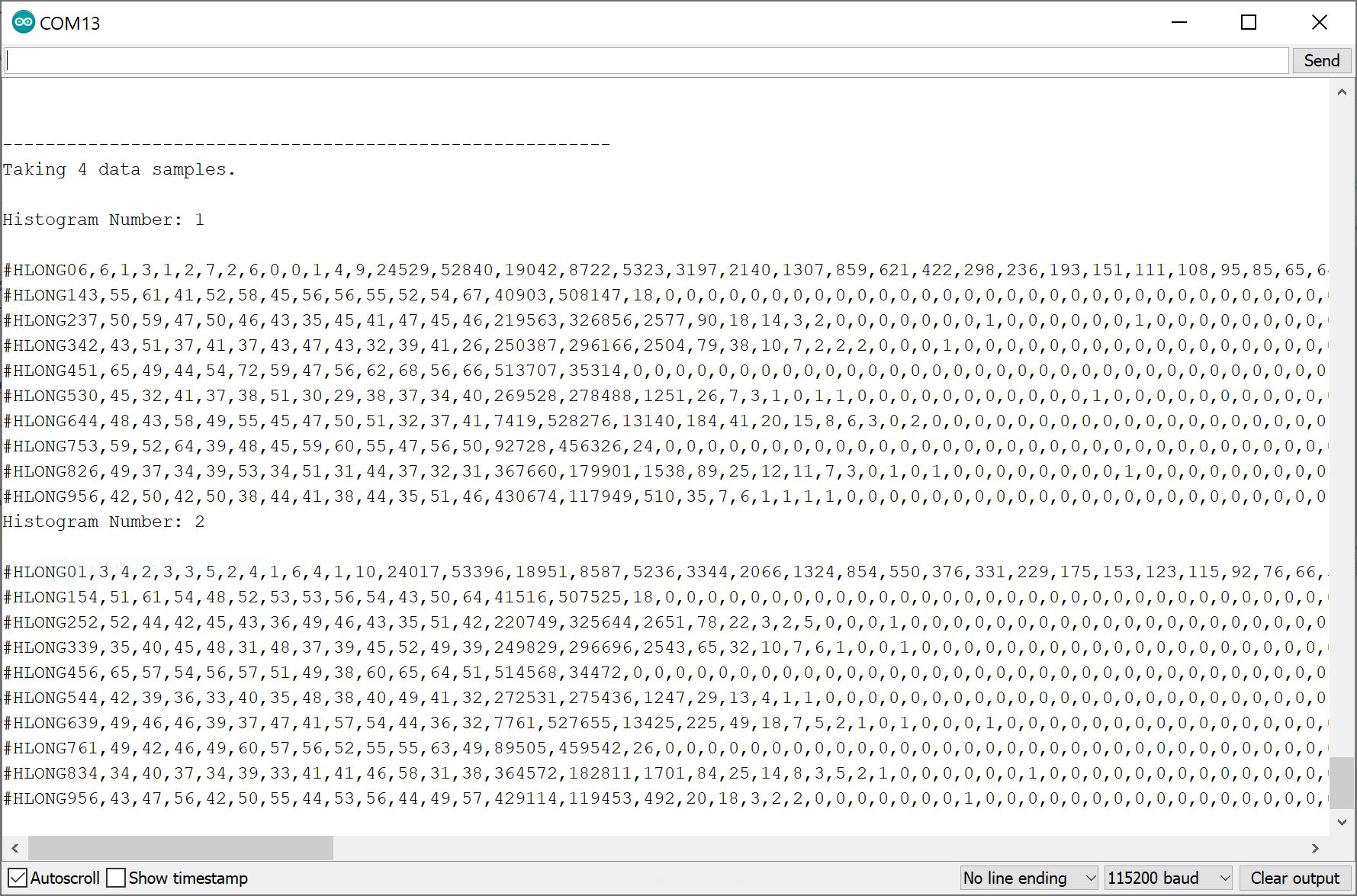
Open the Arduino Serial Monitor at 115200 baud to view the raw histogram data for your TMF8820 and TMF8821. Note that the example code is currently set to take a 4 data samples at a time. You should see an output similar to the image below if you are covering the sensor.
More Examples!
This tutorial highlights a few examples listed in the Arduino Library to get you started. Additional examples can be found in the library.
Troubleshooting
If you need technical assistance and more information on a product that is not working as you expected, we recommend heading on over to the SparkFun Technical Assistance page for some initial troubleshooting.
If you don't find what you need there, the SparkFun Forums are a great place to find and ask for help. If this is your first visit, you'll need to create a Forum Account to search product forums and post questions.
Resources & Going Further
Now that you've successfully got your Qwiic dToF Imager up and running, it's time to incorporate it into your own project! For more information, check out the resources below:
- SparkFun Qwiic dToF Imager - TMF8820
- SparkFun Qwiic Mini dToF Imager - TMF8820
- SparkFun Qwiic dToF Imager - TMF8821
- SparkFun Qwiic Mini dToF Imager - TMF8821
- TMF882X
- Arduino Library
- GitHub Hardware Repo
- SFE Product Showcase
Need some inspiration for your next project? Check out some of these other tutorials using sensors.