Contributors:
 bboyho
,
 Elias The Sparkiest
,
 Englandsaurus
 Hardware Overview
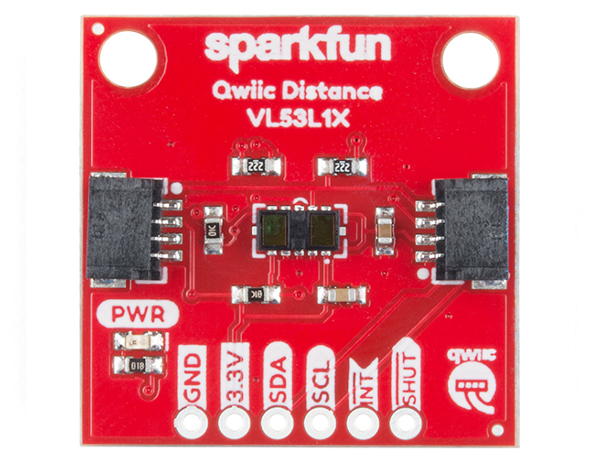
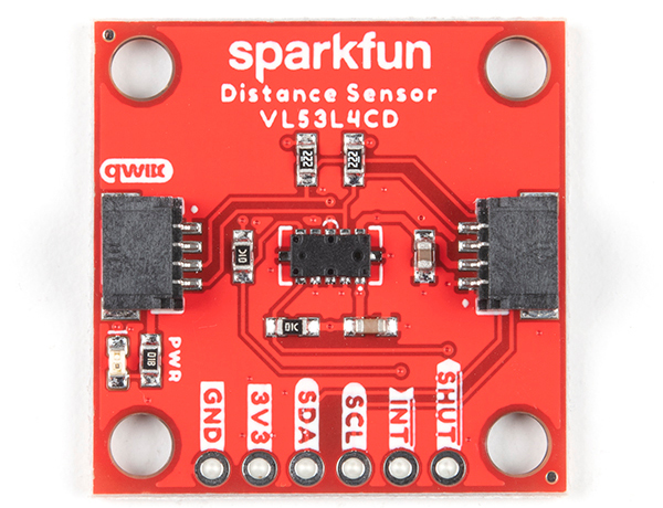
First, let's check out some of the characteristics of the VL53L1X and VL53L4CD we're dealing with, so we know what to expect out of the board. Below is a comparison table for both sensors taken from the datasheet. Typically, the board is powered at 3.3V via the Qwiic connector.
| Characteristic | VL53L1X | VL53L4CD |
|---|
| Operating Voltage | 2.6V to 3.5V |
| Power Consumption | 20 mW @10Hz | - |
| Current Consumption | 18mA | 24mA |
| Measurement Range | ~40mm to 4,000mm | 1mm to 1300mm |
| Resolution | ±1mm |
| Light Source | Class 1 940nm VCSEL |
| I2C Address | 0x29 |
| Field of View | 15° to 27° | 18° |
| Max Read Rate | 50Hz | 100Hz |
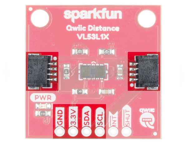
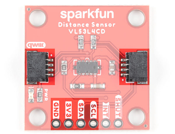
Pins
The following table lists all of the VL53L1X and VL53L4CD's pins and their functionality.
 |
 |
| VL53L1X |
VL53L4CD |
| Pin | Description | Direction |
|---|
| GND | Ground | In |
| 3.3V | Power | In |
| SDA | Data | In |
| SCL | Clock | In |
| INT | Interrupt, goes low when data is ready. | Out |
| SHUT | Shutdown, can be pulled low to put the IC in shutdown mode. | In |
Qwiic and I2C
Both breakout boards include 2x Qwiic connectors to easily access the I2C data lines and power. The Qwiic ecosystem is made for fast prototyping by removing the need for soldering. All you need to do is plug a Qwiic cable into the Qwiic connector and voila! Of course, you can still solder header pins or wires to the PTHs. The I2C address for each sensor is 0x29 (7-bit unshifted) as stated earlier. You may notice that the datasheet and library use 0x52, which is the address shifted.
 |
 |
| VL53L1X |
VL53L4CD |
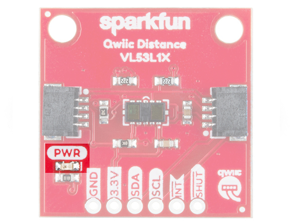
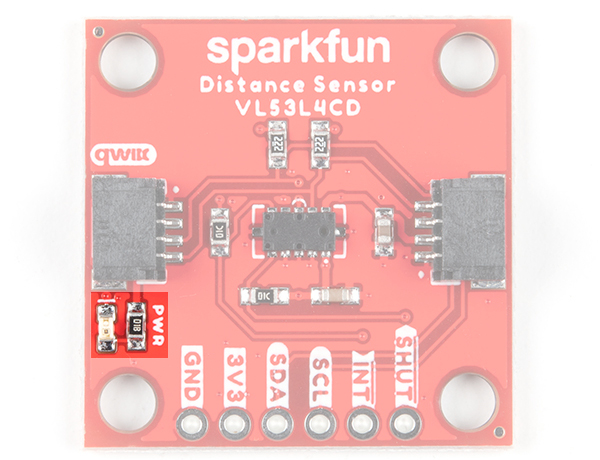
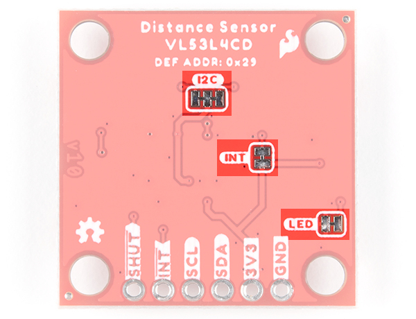
LED
The onboard power LED (PWR) will light up when the board is powered. Exclusively for the VL53L4CD, this can be disabled by cutting the jumper labeled as LED on the back of the board.
 |
 |
| VL53L1X |
VL53L4CD |
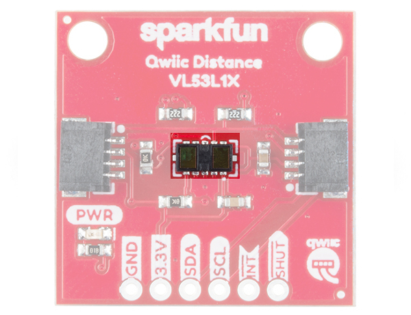
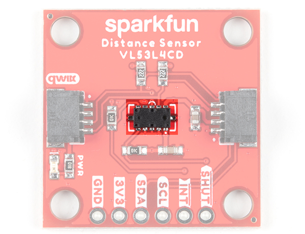
Sensor and IR Laser
On the left side of each sensor IC is a single photon avalanche diode (SPAD) array. On the other side of each sensor IC is an invisible IR laser. The wavelength of the lasers found in the VL53L1X and VL53L4CD is 940nm and are classified as a Class 1 laser emitter. We found that the sensors worked best when left uncovered in your application to avoid crosstalk. If you do place a transparent material (material transmission should be greater than 85%) in front of the sensor, it is recommended to have an air gap that is as small as possible to avoid errors in sensor readings.
 |
 |
| VL53L1X |
VL53L4CD |
Note: While the IR laser is invisible to the human eye, you can view the laser at an angle using a camera. If you take out your smartphone and view the sensor through the camera, you can see the IR laser being emitted from the sensor!
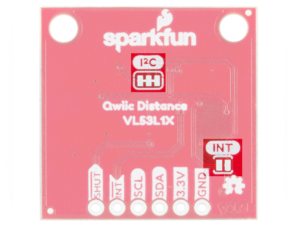
Jumpers
The VL53L1X and VL53L4CD breakout boards include jumpers on the back of the board. If you need to disconnect any of the jumpers, they can be removed by cutting the traces on the corresponding jumpers highlighted below.
- I2C - By default, this 3-way jumper is closed by default. The 2.2kΩ pull-up resistors are attached to the I2C bus; if multiple sensors are connected to the bus with the pull-up resistors enabled, the parallel equivalent resistance will create too strong of a pull-up for the bus to operate correctly. As a general rule of thumb, disable all but one pair of pull-up resistors if multiple devices are connected to the bus.
- INT - By default, this jumper is closed by default. This is connected to the 10kΩ pull-up resistor.
- LED - Exclusive to the VL53L4CD, this jumper is closed by default. Cutting this jumper will disable the PWR LED.
 |
 |
| VL53L1X |
VL53L4CD |
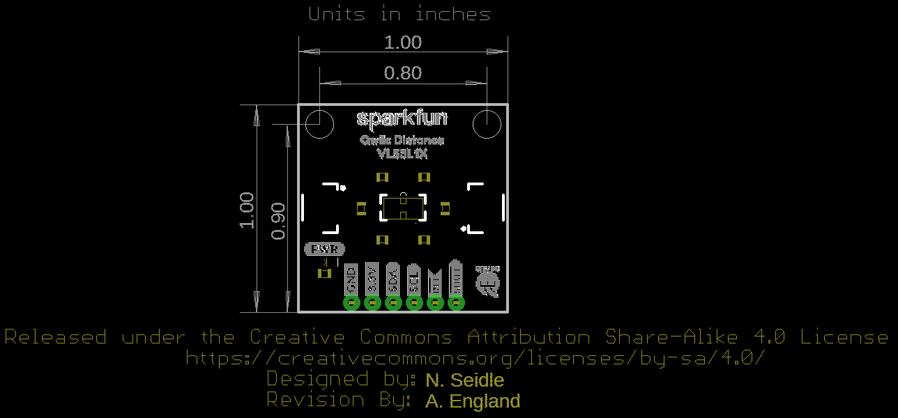
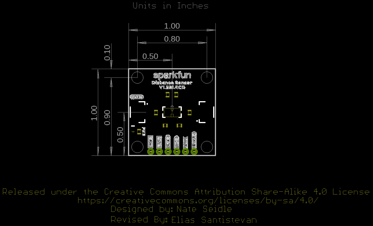
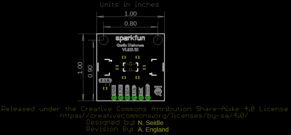
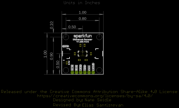
Board Dimensions
The board dimensions of both boards use the Qwiic standard board size of 1.0"x1.0". The VL53L1X has two mounting holes on two corners of the board while the VL53L4CD has four mounting holes on each corner of the board.
 |
 |
| VL53L1X |
VL53L4CD |