Qwiic Atmospheric Sensor (BME280) Hookup Guide
 QCPete, santaimpersonator
Hardware Overview
Power
There is a power status LED to help make sure that your Qwiic Atmospheric Sensor is getting power. You can power the board either through the polarized Qwiic connector system or the breakout pins (3.3V and GND) provided. This Qwiic system is meant to use 3.3V, be sure that you are NOT using another voltage when using the Qwiic system.
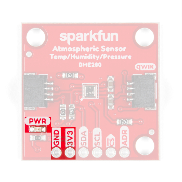
If you want to conserve power, there is an available jumper on the back of the board labeled LED to cut power to the LED (see Jumpers section below).
BME280 Sensor
The Bosch BME280 is the atmospheric sensor used on this board. It measures three different atmospheric properties: ambient temperature, (relative) humidity, and barometric pressure.
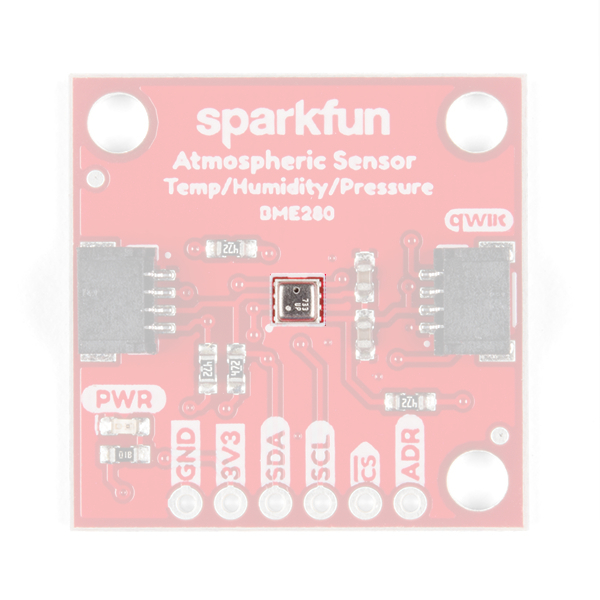
The BME280 uses three modes of operation: sleep mode, forced mode and normal mode. These modes dictate how the sensor performs measurement cycles. The BME280 can be interfaced via I2C (used with Qwiic connections) or SPI communication. In the table below, are some of the characteristics of the BME280 sensor from the datasheet:
| Characteristic | Description |
|---|---|
| Operating Voltage (VDD) | 1.71V to 3.6V (Default on Qwiic System: 3.3V) |
| Operational Modes | Sleep (Default), Normal, and Forced (low power; single measurement) |
| Data Output |
16-bit output from ADC (*IIR filter and oversampling can increase this to 20-bit; excludes humidity data.) |
| Current Consumption (Typical) |
Sleep: 0.3 µA Standby: 0.5 µA (inactive period of normal mode) Humidity Measurements: 340 µA (peaks at 85°C) Pressure Measurements: 714 µA (peaks at -40°C) Temperature Measurements: 350 µA (peaks at 85°C) |
Humidity Parameters |
Range: 0 to 100 %RH Absolute Accuracy: ±3 %RH (from 20 - 80 %RH) Resolution: 0.008 %RH Forced Mode Current Consumption: 2.8 µA (max) |
| Pressure Parameters |
Range: 300 to 1100 hPa (30,000 - 110,000 Pa or approx. 4.35 - 15.95 PSI) Absolute Accuracy: ±(1 - 1.7) hPa Resolution: 0.18 Pa Forced Mode Current Consumption: 4.2 µA (max) |
| Temperature Parameters |
Range: 0°C to 65°C (32°F to 149°F) Absolute Accuracy: ±(0.5 - 1.5)°C Resolution: 0.01°C Forced Mode Current Consumption: 1.0 µA (typical) |
| I2C Address | 0x77 (Default) or 0x76 |
Modes of Operation
The BME280 offers three modes of operation:
- Sleep mode (Default): No operation, all registers accessible, lowest power, selected after startup.
- Forced mode (low power operation): Performs one measurement, store results and return to sleep mode.
- Normal mode (active measurements): Perpetual cycling of measurements and inactive periods.
For more details, refer to sections 3.3.2-4 in the datasheet. Additionally, in section 3.5 the are a set of recommended sensor settings for various applications or operations.
Measurements
All measurements can be skipped or enabled. When enabled, there are several oversampling options; with oversampling, it is possible to reduce the noise.
For more details, refer to sections 3-4 in the datasheet.
Humidity
The resolution of the humidity measurement is fixed at 16-bit ADC output. A graph of the operational range for the humidity sensor (shaded in grey) is shown below; the sensor will not report and/or operate properly outside of this range.

Pressure and Temperature
For temperature and pressure readings, the resolution of the data will be dependent on if the infinite impulse response (IIR) filter is enabled and the oversampling setting register setting (osrs):
- When the IIR filter is enabled, the measurement resolution is 20-bit.
- When the IIR filter is disabled, the measurement resolution is [16 + (osrs–1)]-bit.
- e.g. The temperature measurement is 18-bit when osrs_t is set to ‘3’.
(*Note: The temperature value depends on the PCB temperature, sensor element self-heating and ambient temperature and is typically just above ambient temperature.)
Data Analysis
Below are other important attributes of the sensor. For most users, this information is will either be outside their scope or trivial. However for those that are interested, these topics have been briefly summarized or quoted directly from the datasheet. For full details, please refer to the datasheet; additionally, some of the comments in the library may help.
Infinite Impulse Response Filter
- It is recommended that the internal IIR filter be implemented to dampen rapid data fluctuations from external influences like wind blowing, closing doors, etc.
Noise
- The expected noise in the measurement data is dependent on the oversampling setting. For pressure and temperature readings, it is also dependent on the IIR filter setting used.
Trimming Parameters
- The trimming parameters are programmed into the devices’ non-volatile memory (NVM) during production and cannot be altered by users. These are used for the calibration/compensation parameters.
Compensation formulas
- It is strongly advised (by the manufacturer) to use the API available from Bosch Sensortec to perform readout and compensation.
Qwiic or I2C
I2C Address
The BME280 has 2 available I2C addresses, which are set by the address pin, ADR. On the Qwiic Atmospheric sensor, the default peripheral address of the BME280 is 0x77 (HEX).
Default I2C Peripheral Address: 0x77
I2C Registers
The BME280 register (memory) map is detail in section 5.3 of the datasheet.
| Address | Description |
|---|---|
| 0xD0 | ID: The chip identification number. |
| 0xE0 | Soft Reset: If the value 0xB6 is written to the register, the device is reset using the complete power-on-reset procedure |
| 0xF2 | ctrl_hum: Sets the humidity data acquisition options of the device. Changes to this register only become effective after a write operation to ctrl_meas. |
| 0xF3 |
status: Indicate the status of the device.
Whether a conversion is running or the results have been transferred to the data registers.
Whether NVM data are being copied to image registers. |
| 0xF4 | ctrl_meas: Sets the pressure and temperature data acquisition options of the device. The register needs to be written after changing ctrl_hum for the changes to become effective./td>
|
| 0xF5 | config: Sets the rate, filter and interface options of the device. Writes to the config register in normal mode may be ignored. In sleep mode writes are not ignored. |
| 0xF7 to 0xF9 | press: The raw pressure measurement data. |
| 0xFA to 0xFC | temp: The raw temperature measurement data. |
| 0xFD to 0xFE | hum: The raw humidity measurement data. |
|
0xE1 to 0xF0 0x88 to 0xA1 |
Calibration Data: Holds Trimming Parameters. |
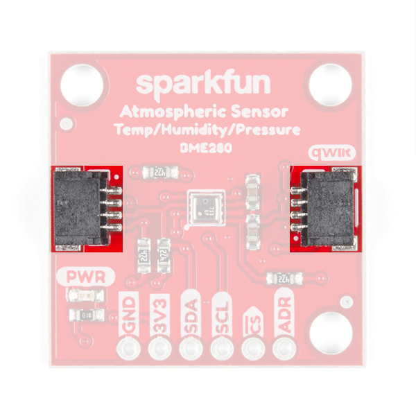
Connections
The simplest way to use the Qwiic ADC is through the Qwiic connect system. The connectors are polarized for the I2C connection and power. (*They are tied to their corresponding breakout pins.)
However, the board also provides six labeled breakout pins. You can connect these lines to the I2C bus of your microcontroller and power pins (3.3V and GND), if it doesn't have a Qwiic connector. Otherwise, the breakout pins can also be used for an SPI connection.
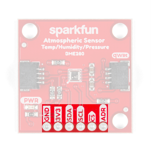
| Pin Label | Pin Function | Input/Output | Notes |
|---|---|---|---|
| 3.3V | Power Supply | Input | 3.3V on Qwiic system (should be stable) |
| GND | Ground | Input | Ground and Single-Ended Reference Voltage for ADC. |
| SDA | I2C Data Signal | Bi-directional | Bi-directional data line. Voltage should not exceed power supply (e.g. 3.3V). |
| SCL | I2C Clock Signal | Input | Clock signal. Voltage should not exceed power supply (e.g. 3.3V). |
SPI Connection
There are two options for an SPI connection 3-wire or 4-wire. For a 3-wire connection, users will need to cut the ADR jumper on the board. For a 4-wire connection users can cut the ADR, I2C, and CS jumpers to remove the load from the SPI lines, but it is not necessary. For more details, check out the notes in the schematic.
This tutorial will not go into detail about using an SPI connection as the Python library can only be used with an I2C connection. However, for users seeking an SPI setup, they can refer to the hookup guide for the original BME280 Sensor Breakout board.
| Pin Label | Pin Function | Input/Output | Notes |
|---|---|---|---|
| 3.3V | Power Supply | Input | Supply voltage for sensor. SHould be regulated between 1.8 and 3.6 V |
| GND | Ground | Input | Ground |
| SCK | Clock Signal | Input | Clock signal. Voltage should not exceed power supply (max. 3.6V). |
| SDI | Data In | Input | Data incoming to the BME280. Voltage should not exceed power supply (max. 3.6V). |
| SDO | Data Out | Output | Data coming from the BME280. |
| CS |
Chip Select |
Input | Used to select device communication on 4-wire connections (active low). Voltage should not exceed power supply (max. 3.6V). |
Jumpers
There are 4 separate jumpers on the board for various hardware related functions. For more notes, check out the hardware schematic. Not sure how to modify a jumper? Read here!
LED Power
If you want to conserve power, the jumper labeled LED will allow users to isolate power to the power status indicator LED.

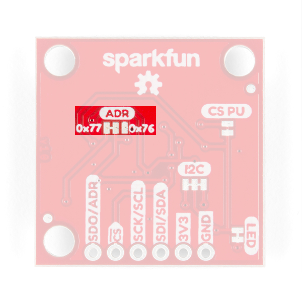
I2C Address
If you want to change the I2C address for the sensor, the jumper labeled ADR will allow users to change the I2C address from the default (0x77) to 0x76.
Pull-Up Resistors
There are two jumpers (well technically three) for the pull-up resistors attached to specific pins on the sensor.
I2C Pull-Ups
The first set of pull-up resistors are tied to the SDA and SCL lines for an I2C connection. Cutting the I2C jumper will remove the 4.7kΩ pull-up resistors from the I2C bus. If you have many devices on your I2C bus you may want to remove these jumpers. (When there are multiple devices on the bus with pull-up resistors, the equivalent parallel resistance may create too strong of a pull-up for the bus to operate correctly.)

CS (and SPI) Pull-Ups
The last pull-up resistor is tied to CS pin for an SPI connection. Cutting the CS jumper will remove the 4.7kΩ pull-up resistor.
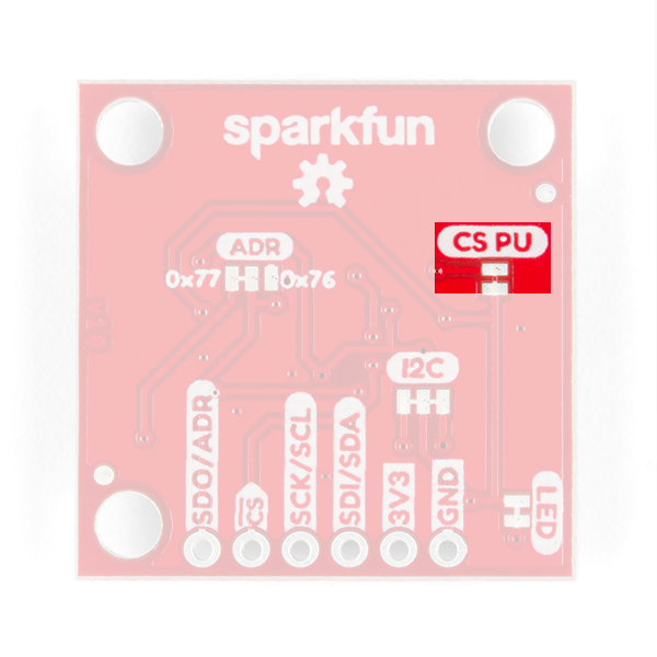
Keep in mind that the rest of the SPI pins are shared with other pins (see the note above on the SPI connection or the schematic). For a 3-wire connection, users will need to cut the ADR jumper for the SDO line. For a 4-wire connection users can cut the ADR, I2C, and CS jumpers to remove the load from the SPI lines, but it is not necessary.